2AHCYRGBCCTRF Wall Switch
Rev-A-Shelf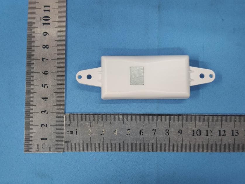
Click to zoom
Application Details
- Equipment Class
- DXX - Part 15 Low Power Communication Device Transmitter
- Date of Grant
- Nov 29, 2020
- Application Purpose
- Original Equipment
- Date of Application
- Nov 29, 2020
- Equipment Note
- RF Wall Switch
- Frequency Range
- 916.50000000 - 916.50000000
- Company
- Rev-A-Shelf
- Country
- United States
Documents & Files
Document Text
Text extracted from the exhibit documents filed with the FCC. Open a document above to read the original.
Users Manual
4 ” 103mm 1” 27mm 1 ” 33mm ” 13mm ” 13mm Fr eeDim RGB/CCT Wall Controllers (AARAS) < upd 1020m Fr ont views Housing Side views R GB 2 61mm 1” 27mm W C READ ALL INSTRUCTIONS BEFORE INSTALLING SYSTEM. Before beginning installation, be sure power is turned OFF to light system. Tresco ® FREEDiM Wall Controllers provide color control for RGB lighting or warm/ cool controls for CCT (white color-tunable) lighting on Tresco ® low voltage LED RGB and CCT lights. They also control the intensity (dim levels) of the lights. The digital screen on the FREEDiM Parent Controller displays the current mode and settings. The wireless Wall Controller must be positioned within 50 ft. (15m) of the Parent Controller. Note: outside interference may affect the signal between Wall Controller and Parent Controller or Child Receiver. (see ‘Signal Interference’ on page 2) The Wall Controller's mounting cradle (see Figure 1) allows installation directly to drywall or to a standard wall electrical box, giving the appearance of a hardwired wall switch. Verify power to outlet box is off before installing. (see Figure 2 for installation options) The Wall Controller has a magnet to hold it within the mounting cradle or to place on any magnetic surface (i.e. refrigerator door). To remove Wall Controller from mounting cradle use the slight indents on the top and bottom edges of Controller. The mounting cradle has an index tab to orient the Wall Controller in the proper "up" position. (see Figure 1) Tresco’s FREEDiM Parent Controllers and Child Receivers can be used with any Class 2, 12VDC/60W or 24VDC/96W Power Supply. As an option, Tresco ® Power Supplies are available: (see Power Supplies on Figure 3 & 4) 12VDC/60W max. part no.: L-DC-SLELT60-1, and 24VDC/96W max. part no.: L-24DCELT96-1 For more Power Supply options, see Tresco ® Specifications Catalog. Installing Parent Controller: NOTE: All wiring must follow local codes and NEC regulations. 1. Verify power is turned off to light system. Connect Parent Controller input wire to 12VDC or 24VDC Power Supply output wire (see Figures 3 & 4). 2. If using Tresco Power Supplies, connect Parent Controller input wire to 12VDC Mounting Block or 24VDC 5-Output Barrel Splice (see Figures 3 & 4). Otherwise follow installation guide of power supply used. To use multiple Parent Controllers or Child Receivers on one Power Supply, the optional 12VDC Mounting Block (P/N: L-TRANS-MNT-BL) can accept 6 Parent Controllers and/or Child Receivers. The optional 24VDC 5-Output Barrel Splice (P/N: L-1BRL5-1) can accept 5 Parent Controllers and/or Child Receivers. Use insulated staples or plastic ties to secure ALL loose cords. 3. With RGB or CCT light(s) connected to a starter cord, plug the starter cord into the Parent Controller or Child Receiver(s) 4-Position Amp Output Connector. Child Receivers must be used with Parent Controller. To connect multiple RGB or CCT light(s) to a single Parent Controller or Child Receiver use the optional 4-Position 6-Output Adaptor Cord (P/N: L- 4P6O-1). Plug the input wire of the Adaptor Cord to the 4-Position Amp Connector on the output of the Parent Controller or Child Receiver. Then plug the desired RGB or CCT light(s) starter cords into any of the 6 outputs of the Adaptor Cord. The 4-Position 6-Output Adaptor Cord works with 12VDC/5A and 24VDC/4A systems as well as RGB and Color Tunable White Lights. 4. Check all connections and turn on power to the Power Supply. 5. Check the mode on the Parent Controller and select either RGB or CCT mode depending on the LED light system installed. NOTE: See separate instruction sheets for further information on Tresco ® low voltage LED RGB and CCT lights, FREEDiM Parent Controllers and Child Receivers, and Tresco ® Power Supplies. See page 2 for further instructions. Accessories (sold separately): Extension and Link Cords, additional Parent Controllers, Child Receivers, Wall Controllers, 12V Mounting Blocks, 24V 5-Output Barrel Splices, 4-Position 6-Output Adaptor Cords. Options to Install Mounting Cradle in a Wall Option 1: Option 2: Option 3: Non-Metallic Low-Voltage Bracket Single Outlet Box Multiple Outlet Box (e.g. Carlon ® Model #SC100R) Installation Instructions FREEDiM Wireless RGB & CCT Wall Controllers Single Zone • 12VDC 60W & 24VDC 96W RGB Wall Controller Mounting Cradle Front views Side views Index Tab to orient Controller Fr eeDim Wall Controller (AARAS) < upd 1020 m Fr eeDim Wall Controller (AARAS) < upd 1020 m Cover with a Decora ® style wall plate #1 CCT Wall Controller #2 System Parts: (1) Wall Controller - RGB ............................. P/N: L-WLD-RGB-WH-1 (1) Wall Controller - Color Tunable White ............... P/N: L-WLD-CCT-WH-1 (1) Dynamic Parent Controller (12/24VDC) (required) ........ P/N: L-RGBCCT1-PREC (1) Dynamic RF LED Child Receiver (12/24VDC) (optional).... P/N: L-RGBCCT1-CREC (1) Power Supply, Class 2, 12VDC 60W max (or) 24VDC 96W max Tresco ® low voltage 12VDC or 24VDC LED RGB or CCT light(s) with Starter Cord Also see Accessories below. Wall Controller Specifications: Operating Voltage: . . . . (1) CR1620 battery (included) Radio Frequency: ..... 916.5 MHz RF Remote Distance: .. 50 ft. (15m) Parent Controller & Child Receiver Specifications: Input Voltage: ... 12VDC or 24VDC Output: ....... 12VDC (5A, 60W), or 24VDC (4A, 96W) Orig IN IN PDF from RAS 116 called “I-WLDIM1RND” WATCH! old lines have “double-lines” w layers. See Hidden Layer for orig IL. > GRX ip & rework middle IL only on 1217 MP ... But since converted to G5 !!! 218 (u.519, 619) RF LED Receiver RF LED Controller OUTPUT 12 VDC Typical 24V Installation Showing example of RGB 4-Wire installation with optional Tresco products Orig IN IN PDF from RAS 116 called “I-WLDIM1RND” WATCH! old lines have “double-lines” w layers. See Hidden Layer for orig IL. > GRX ip & rework middle IL only on 1217 MP ... But since converted to G5 !!! 218 (u.519, 619) LED Power Supply 12 VDC Install Wall Dimmer on input (line voltage) side of Powe…
Text truncated - open the document above for the full version.
Cover Letter(s)
Rev-A-Shelf Agent Authorization Company: Rev-A-Shelf Address: 12400 Earl Jones Way Louisville, Kentucky 40299, United States Product Name: RF Wall Switch Model Number(s): WLD-RGB-WH, WLD-CCT-WH Product Description: RF Wall Switch We authorize MiCOM Labs Inc., 575 Boulder Court, Pleasanton, California 94566, USA, to act on our behalf on all matters concerning the certification of above named equipment. We declare that MiCOM Labs Inc. is allowed to forward all information related to the approval and certification of equipment to the regulatory agencies as required and to discuss any issues concerning the approval application. Any and all acts carried out by MiCOM Labs on our behalf shall have the same effect as acts of our own. Signature: Date: 2020-09-08 Name: Chris Tress Title: Director Company: Rev-A-Shelf
Cover Letter(s)
Rev-A-Shelf Office of Engineering Technology Federal Communications Commission 7435 Oakland Mills Road Columbia, MD21046 Date: 2020-09-08 Subject; Request for Long Term Confidentiality FCC ID: 2AHCYRGBCCT To Whom It May Concern, Pursuant to the provisions of the Commission’s rules Title 47 Sections §0.457 and §0.459, we are requesting the Commission to withhold the following attachment(s) as confidential documents from public disclosure indefinitely. These documents contain detailed system and equipment descriptions and are considered as proprietary information in operation of the equipment. The public disclosure of these documents might be harmful to our company and would give competitors an unfair advantage in the market. Schematic Diagram Block Diagram Operational Description It is our understanding that all measurement test reports, FCC ID label format and correspondence during the certification review process cannot be granted as confidential documents and this information will be available for public review once the grant of equipment authorization is issued. Sincerely, Signature: Name: Chris Tress Title: Director
Cover Letter(s)
Differences Declaration To whom concern, We company Rev-A-Shelf hereby declares: The product models WLD-RGB-WH, WLD-CCT-WH are identical in the same PCB layout, interior structure and electrical circuits, the only difference is the model name for commercial purpose. Authorized signature: Name: Chris Tress Date: 2020-09-08
External Photos
Test Model No.: WLD-RGB-WH Model No.: WLD-CCT-WH
ID Label/Location Info
FCC ID:2AHCYRGBCCT
Internal Photos
Test Model No.: WLD‐RGB‐WH
Test Report
Global United Technology Services Co., Ltd. Report No.: GTS202009000039F01 Authorized Signature: Robinson Lo Laboratory Manager This results shown in this test report refer only to the sample(s) tested, this test report cannot be reproduced, except in full, without prior written permission of the company. The report would be invalid without specific stamp of test institute and the signatures of compiler and approver. Page 1 of 18 TEST REPORT Applicant: Rev-A-Shelf Address of Applicant: 12400 Earl Jones Way Louisville, Kentucky 40299, United States Manufacturer/Factory: Rev-A-Shelf Address of Manufacturer/Factory: 12400 Earl Jones Way Louisville, Kentucky 40299, United States Equipment Under Test (EUT) Product Name: RF Wall Switch Model No.: WLD-RGB-WH, WLD-CCT-WH FCC ID: 2AHCYRGBCCT Applicable standards: FCC CFR Title 47 Part 15 Subpart C Section 15.249 Date of sample receipt: September 04, 2020 Date of Test: September 04-08, 2020 Date of report issued: September 08, 2020 Test Result : PASS * * In the configuration tested, the EUT complied with the standards specified above. Report No.: GTS202009000039F01 Global United Technology Services Co., Ltd. No. 123-128, Tower A, Jinyuan Business Building, No.2, Laodong Industrial Zone, Xixiang Road, Baoan District, Shenzhen, Guangdong, China 518102 Telephone: +86 (0) 755 2779 8480 Fax: +86 (0) 755 2779 8960 Page 2 of 18 2 Version Version No. Date Description 00 September 08, 2020 Original Prepared By: Date: September 08, 2020 Project Engineer Check By: Date: September 08, 2020 Reviewer Report No.: GTS202009000039F01 Global United Technology Services Co., Ltd. No. 123-128, Tower A, Jinyuan Business Building, No.2, Laodong Industrial Zone, Xixiang Road, Baoan District, Shenzhen, Guangdong, China 518102 Telephone: +86 (0) 755 2779 8480 Fax: +86 (0) 755 2779 8960 Page 3 of 18 3 Contents Page 1 COVER PAGE ............................................................................................................................................ 1 2 VERSION .................................................................................................................................................. 2 3 CONTENTS .............................................................................................................................................. 3 4 TEST SUMMARY ..................................................................................................................................... 4 4.1 MEASUREMENT UNCERTAINTY ............................................................................................................ 4 5 GENERAL INFORMATION ...................................................................................................................... 5 5.1 GENERAL DESCRIPTION OF EUT ......................................................................................................... 5 5.2 TEST MODE ........................................................................................................................................ 6 5.3 DESCRIPTION OF SUPPORT UNITS ....................................................................................................... 6 5.4 DEVIATION FROM STANDARDS ............................................................................................................. 6 5.5 ABNORMALITIES FROM STANDARD CONDITIONS ................................................................................... 6 5.6 TEST FACILITY .................................................................................................................................... 6 5.7 TEST LOCATION ................................................................................................................................. 6 5.8 ADDITIONAL INSTRUCTIONS ................................................................................................................. 6 6 TEST INSTRUMENTS LIST ..................................................................................................................... 7 7 TEST RESULTS AND MEASUREMENT DATA ...................................................................................... 9 7.1 RADIATED EMISSION METHOD ............................................................................................................. 9 7.1.1 Field Strength of The Fundamental Signal and spurious emissions ......................................... 12 7.1.2 Spurious emissions .................................................................................................................... 13 7.2 20DB OCCUPY BANDWIDTH .............................................................................................................. 17 8 TEST SETUP PHOTO ............................................................................................................................ 18 9 EUT CONSTRUCTIONAL DETAILS ..................................................................................................... 18 Report No.: GTS202009000039F01 Global United Technology Services Co., Ltd. No. 123-128, Tower A, Jinyuan Business Building, No.2, Laodong Industrial Zone, Xixiang Road, Baoan District, Shenzhen, Guangdong, China 518102 Telephone: +86 (0) 755 2779 8480 Fax: +86 (0) 755 2779 8960 Page 4 of 18 4 Test Summary Test Item Section Result AC Power Line Conducted Emission 15.207 N/A Field strength of the fundamental signal 15.249 (a) Pass Spurious emissions 15.249 (a) (d)/15.209 Pass Band edge 15.249 (d)/15.205 Pass 20dB Occupied Bandwidth 15.215 (c) Pass Pass: The EUT complies with the essential requirements in the standard. Remark: Test according to ANSI C63.10: 2013 and ANSI C63.4: 2014. 4.1 Measurement Uncertainty Test Item Frequency Range Measurement Uncertainty Notes Radiated Emission 30MHz-200MHz 3.8039dB (1) Radiated Emission 200MHz-1GHz 3.9679dB (1) Radiated Emission 1GHz-18GHz 4.29dB (1) Radiated Emission 18GHz-40GHz 3.30dB (1) AC Power Line Conducted Emission 0.15MHz ~ 30MHz 3.44d…
Text truncated - open the document above for the full version.
Test Setup Photos
Test Model No.: WLD-RGB-WH Radiated Emission
Contact Information
Applicant
Chris Tress(Director)
Technical Contact
Test Firm
Global United Technology Services Co. Ltd.Robinson Lo
Technical Specifications
| # | Rule Parts | Frequency Range | Power Output |
|---|---|---|---|
| 1 | 15C | 916.5 MHz - 916.5 MHz | - |
Other Applications from Rev-A-Shelf
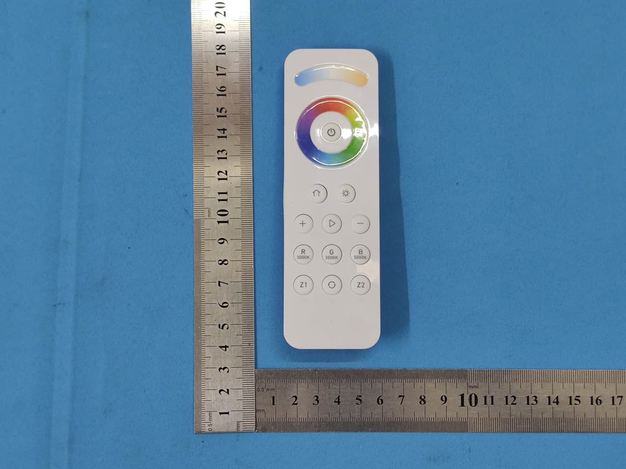
2AHCYRGBCCT-RMT
Sep 22, 2020RF Remote
Equipment Class
DXX - Part 15 Low Power Communication Device Transmitter