2AHCYRGBCCT-RMTRF Remote
Rev-A-Shelf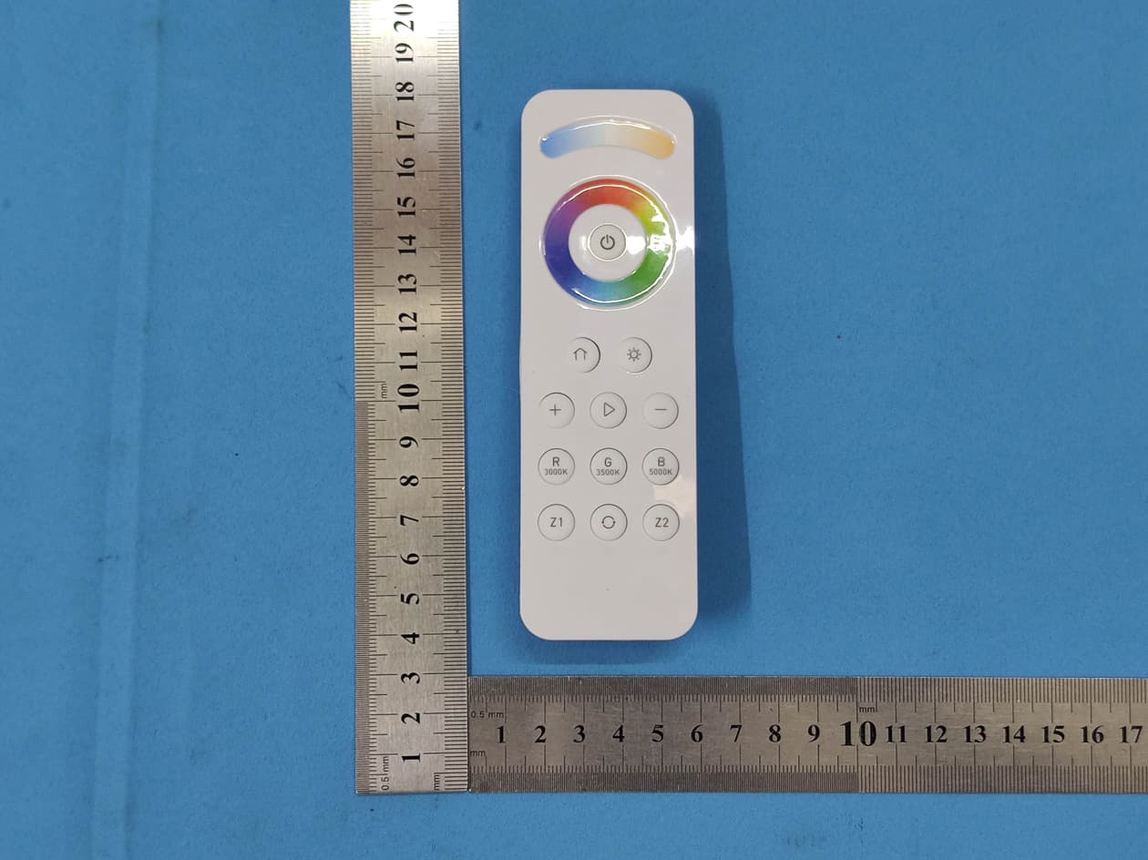
Click to zoom
Application Details
- Equipment Class
- DXX - Part 15 Low Power Communication Device Transmitter
- Date of Grant
- Sep 22, 2020
- Application Purpose
- Original Equipment
- Date of Application
- Sep 21, 2020
- Equipment Note
- RF Remote
- Frequency Range
- 916.50000000 - 916.50000000
- Company
- Rev-A-Shelf
- Country
- United States
Documents & Files
Document Text
Text extracted from the exhibit documents filed with the FCC. Open a document above to read the original.
Users Manual
System Parts: (1) Dynamic RF LED Remote Control . . . . . . . . . . . . . . . P/N: L-RGBCCT-RMT (1) Dynamic RF LED Parent Controller . . . . . . . . . . . . . . P/N: L-RGBCCT1-PREC (1) Dynamic RF LED Child Receiver (optional) . . . . . . . . P/N: L-RGBCCT1-CREC (1) Power Supply, Class 2, 12VDC 60W max (or) 24VDC 96W max Tresco ® low voltage 12VDC or 24VDC LED RGB or CCT light(s) with Starter Cord Instructions FREEDiM Dynamic RF Remote Control For RGB & CCT LEDs • 12VDC 60W & 24VDC 96W R 3000K G 3500K B 5000K Z1 Z2 RGB CCT Remote Control L-RGBCCT-RMT “On” Indicator Light CCT Slider for CCT control (slide with finger touch) RGB Color Wheel for RGB control (rotate with finger touch) “On/Off” Button R G B Z1 Z2 3000K 3500K 5000K Dim Button Dims up or down R G B Z1 Z2 3000K 3500K 5000K R G B Z1 Z2 3000K 3500K 5000K R G B Z1 Z2 3000K 3500K 5000K RGB Buttons Quick preset buttons – In RGB mode, quickly go to preset Red, Green or Blue colors R G B Z1 Z2 3000K 3500K 5000K R G B Z1 Z2 3000K 3500K 5000K R G B Z1 Z2 3000K 3500K 5000K CCT Buttons Quick preset buttons – In CCT mode, quickly go to preset Warm (3000K), Neutral (3500K), or Cool (5000K) light R G B Z1 Z2 3000K 3500K 5000K Switch Mode Switches unit between RGB and CCT modes Home Button R G B Z1 Z2 3000K 3500K 5000K Takes any settings back to Start (Starts over at preset settings, but does not erase pairing) Speed-up Button R G B Z1 Z2 3000K 3500K 5000K Increases the speed of whatever RGB program running Play Button R G B Z1 Z2 3000K 3500K 5000K Starts the pre-set programs . Hit play again stops that program . Hit play again moves to the next program . Speed-down Button R G B Z1 Z2 3000K 3500K 5000K Decreases the speed of whatever RGB program running Zone 1 & Zone 2 Buttons R G B Z1 Z2 3000K 3500K 5000K R G B Z1 Z2 3000K 3500K 5000K Switches between Zones 1 and 2 for independent zone functions The FREEDiM Remote Control starts out with preset settings: • RGB preset - all values start at 0-0-0 • CCT preset - begins at 2700K Remote Control Specifications: Operating Voltage: . . . . . . . . . . . . . . . . (2) AAA batteries (included) Radio Frequency: . . . . . . . . . . . . . 916 .5 MHz RF Remote Distance: . . . . . . . . . . 66 ft . (20m) RGB and CCT full-function controls: The Tresco ® FREEDiM Remote Control provides color and brightness controls for RGB or CCT (white color-tunable) lighting on Tresco ® low voltage LED RGB and CCT lights . It also controls the intensity (dim levels) of the lights up to 95% . The digital screen on the FREEDiM Parent Controller displays the current mode and settings . The wireless Remote Control must be positioned within 66 ft . (20m) of Parent Controller and any Child Receivers . Note: outside interference may affect the signal between Remote Control and Parent Controller . (see ‘Signal Interference’ on page 2) RGB and CCT modes: Prior to installation you need to select between RGB or CCT LED lights . Then after installation, you must select either RGB or CCT mode on the Parent Controller . (see the Switch Mode button above, in Fig 1) See separate instruction sheets for further information on Tresco® low voltage LED RGB and CCT lights, FREEDiM Parent Controllers and Child Receivers, and Power Supplies. Pairing the Remote Control to the Parent Controller 1 . First install the Parent Controller with either a RGB or CCT LED light system and then turn on the Parent Controller . 2 . Check the mode on the Parent Controller and select either RGB or CCT mode depending on the LED light system installed . 3 . On the Remote Control hit the ON button R G B Z1 Z2 3000K 3500K 5000K . - The small indicator light in top corner is now red, indicating that the Remote Control is live and active (this light stays on for 30 sec .) (see Fig. 1 above) . 4 . Using the Switch Mode button R G B Z1 Z2 3000K 3500K 5000K , select either RGB or CCT mode . The red indicator light underneath the Switch Mode button indicates RGB mode . 5 . On the Parent Controller press the Learning Key one time . 6 . Next on the Remote Control press the Zone 1 button R G B Z1 Z2 3000K 3500K 5000K . The Zone 1 indicator light underneath is now red (see Fig. 1 above) . 7 . After you have hit the Zone 1 button, touch either the RGB Color Wheel or CCT Slider . Lights will flash once indicating everything is paired . Then repeat steps if adding Zone 2 or more Parent Controllers . Note: Each zone can control 1 Parent Controller and up to 10 Child Receivers . Each zone is independent and must be controlled separately from each other . (see more information and illustration on page 2) Zone 1 Indicator Light RGB Indicator Light # 1 Zone 2 Indicator Light (Instructions continued on page 2) IMPORTANT SAFETY INSTRUCTIONS •Use only in dry locations . Not for use where exposed to the weather . •Replace the batteries on the Remote Control with (2) AAA batteries only (non-rechargeable) . •Clean with a damp cloth . Do not use cleaners or detergents . Page 2 Save these instructions for future reference. For technical assistance, call 1-800-227-1171 Tresco Lighting by Rev-A-Shelf 12400 Earl Jones Way Louisville, KY 40299 Tel: 800-227-1171 Fax: 502-491-2215 Email: cservice@trescolighting .com Web: www .trescolighting .com I-RGBCCTRMT-0720 Signal Interference: Outside interference may affect the signal between the Remote Control and Parent Controller or Child Receiver . Typical items that might cause interference include: metal pots and pans, leaded glass, aluminum framed doors, etc . If experiencing interference, try repositioning the Parent Controller or Child Receiver in 6” (15cm) increments . This typically allows the system to function properly . 2 1 Each Remote Control can control up to 2 Parent Controllers Note: Each zone can handle 1 Parent Controller and up to 10 Child Receivers . # 2 RoHS COMPLIANT Instructions FREEDiM Dynamic RF Remote Control For RGB & CCT LEDs • 12VDC 60W & 24VDC 96W The Built-In 10 Color-changing Modes are as follows: Mode 1: Randomly selects any …
Text truncated - open the document above for the full version.
ID Label/Location Info
RGBCCT-RMT 20 mm 23 mm FCC ID:2AHCYRGBCCT-RMT
RF Exposure Info
RF Exposure evaluation According to 447498 D01 General RF Exposure Guidance v05 The 1-g and 10-g SAR test exclusion thresholds for 100 MHz to 6 GHz at test separation distances≤ 50 mm are determined by: [(max. power of channel, including tune-up tolerance, mW)/(min. test separation distance, mm)] ·[√f(GHz)] ≤ 3.0 for 1-g SAR and ≤ 7.5 for 10- g extremity SAR, where f(GHz) is the RF channel transmit frequency in GHz Power and distance are rounded to the nearest mW and mm before calculation The result is rounded to one decimal place for comparison eirp = pt x gt = (EXd) 2 /30 where: pt = transmitter output power in watts, gt = numeric gain of the transmitting antenna (unitless), E = electric field strength in V/m, --- 10 ((dBuV/m)/20) /10 6 d = measurement distance in meters (m)---3m Sopt = (EXd) 2 /30 x gt Ant gain= 0dBi ; so Ant numeric gain= 1 Field strength =89.19dBμV/m @3m So Pt={ [10 (89.19/20) /10 6 x3] 2 /30x1 }x1000 mW = 0.25 mW So ( 0.25 mW/5mm)x √0.91650 GHz = 0.05 < 3 Then SAR evaluation is not required
Test Report
Global United Technology Services Co., Ltd. Report No.: GTS202008000230F01 Authorized Signature: Robinson Lo Laboratory Manager This results shown in this test report refer only to the sample(s) tested, this test report cannot be reproduced, except in full, without prior written permission of the company. The report would be invalid without specific stamp of test institute and the signatures of compiler and approver. Page 1 of 18 TEST REPORT Applicant: Rev-A-Shelf Address of Applicant: 12400 Earl Jones Way Louisville, Kentucky 40299, United States Manufacturer/Factory: Rev-A-Shelf Address of Manufacturer/Factory: 12400 Earl Jones Way Louisville, Kentucky 40299, United States Equipment Under Test (EUT) Product Name: RF Remote Model No.: RGBCCT-RMT FCC ID: 2AHCYRGBCCT-RMT Applicable standards: FCC CFR Title 47 Part 15 Subpart C Section 15.249 Date of sample receipt: August 26, 2020 Date of Test: August 26-31, 2020 Date of report issued: August 31, 2020 Test Result : PASS * * In the configuration tested, the EUT complied with the standards specified above. Report No.: GTS202008000230F01 Global United Technology Services Co., Ltd. No. 123-128, Tower A, Jinyuan Business Building, No.2, Laodong Industrial Zone, Xixiang Road, Baoan District, Shenzhen, Guangdong, China 518102 Telephone: +86 (0) 755 2779 8480 Fax: +86 (0) 755 2779 8960 Page 2 of 18 2 Version Version No. Date Description 00 August 31, 2020 Original Prepared By: Date: August 31, 2020 Project Engineer Check By: Date: August 31, 2020 Reviewer Report No.: GTS202008000230F01 Global United Technology Services Co., Ltd. No. 123-128, Tower A, Jinyuan Business Building, No.2, Laodong Industrial Zone, Xixiang Road, Baoan District, Shenzhen, Guangdong, China 518102 Telephone: +86 (0) 755 2779 8480 Fax: +86 (0) 755 2779 8960 Page 3 of 18 3 Contents Page 1 COVER PAGE ............................................................................................................................................ 1 2 VERSION .................................................................................................................................................. 2 3 CONTENTS .............................................................................................................................................. 3 4 TEST SUMMARY ..................................................................................................................................... 4 4.1 MEASUREMENT UNCERTAINTY ............................................................................................................ 4 5 GENERAL INFORMATION ...................................................................................................................... 5 5.1 GENERAL DESCRIPTION OF EUT ......................................................................................................... 5 5.2 TEST MODE ........................................................................................................................................ 6 5.3 DESCRIPTION OF SUPPORT UNITS ....................................................................................................... 6 5.4 DEVIATION FROM STANDARDS ............................................................................................................. 6 5.5 ABNORMALITIES FROM STANDARD CONDITIONS ................................................................................... 6 5.6 TEST FACILITY .................................................................................................................................... 6 5.7 TEST LOCATION ................................................................................................................................. 6 5.8 ADDITIONAL INSTRUCTIONS ................................................................................................................. 6 6 TEST INSTRUMENTS LIST ..................................................................................................................... 7 7 TEST RESULTS AND MEASUREMENT DATA ...................................................................................... 9 7.1 RADIATED EMISSION METHOD ............................................................................................................. 9 7.1.1 Field Strength of The Fundamental Signal and spurious emissions ......................................... 12 7.1.2 Spurious emissions .................................................................................................................... 13 7.2 20DB OCCUPY BANDWIDTH .............................................................................................................. 17 8 TEST SETUP PHOTO ............................................................................................................................ 18 9 EUT CONSTRUCTIONAL DETAILS ..................................................................................................... 18 Report No.: GTS202008000230F01 Global United Technology Services Co., Ltd. No. 123-128, Tower A, Jinyuan Business Building, No.2, Laodong Industrial Zone, Xixiang Road, Baoan District, Shenzhen, Guangdong, China 518102 Telephone: +86 (0) 755 2779 8480 Fax: +86 (0) 755 2779 8960 Page 4 of 18 4 Test Summary Test Item Section Result AC Power Line Conducted Emission 15.207 N/A Field strength of the fundamental signal 15.249 (a) Pass Spurious emissions 15.249 (a) (d)/15.209 Pass Band edge 15.249 (d)/15.205 Pass 20dB Occupied Bandwidth 15.215 (c) Pass Pass: The EUT complies with the essential requirements in the standard. Remark: Test according to ANSI C63.10: 2013 and ANSI C63.4: 2014. 4.1 Measurement Uncertainty Test Item Frequency Range Measurement Uncertainty Notes Radiated Emission 30MHz-200MHz 3.8039dB (1) Radiated Emission 200MHz-1GHz 3.9679dB (1) Radiated Emission 1GHz-18GHz 4.29dB (1) Radiated Emission 18GHz-40GHz 3.30dB (1) AC Power Line Conducted Emission 0.15MHz ~ 30MHz 3.44dB (1) Note (1): The measurement…
Text truncated - open the document above for the full version.
Test Setup Photos
Radiated Emission
Contact Information
Applicant
Chris Tress(Director)
Test Firm
Global United Technology Services Co. Ltd.Robinson Lo
Technical Specifications
| # | Rule Parts | Frequency Range | Power Output |
|---|---|---|---|
| 1 | 15C | 916.5 MHz - 916.5 MHz | - |
Other Applications from Rev-A-Shelf
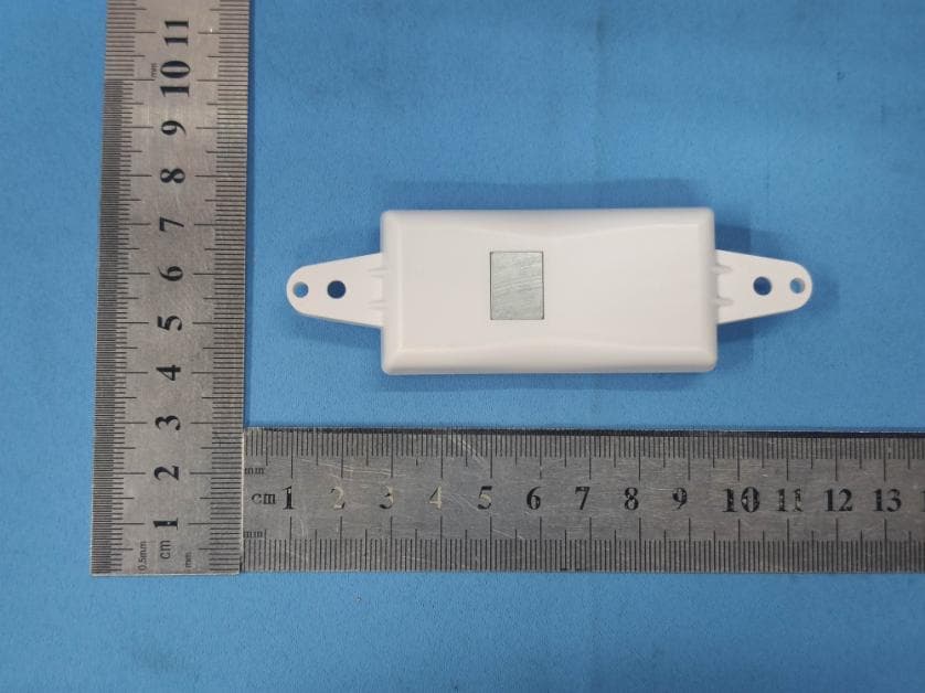
2AHCYRGBCCT
Nov 29, 2020RF Wall Switch
Equipment Class
DXX - Part 15 Low Power Communication Device Transmitter