2AHGJJMSDB2113-49-1RC Sleek Speedboat 49 MHz Remote Controller
JM Manufacturing (HK) Ltd.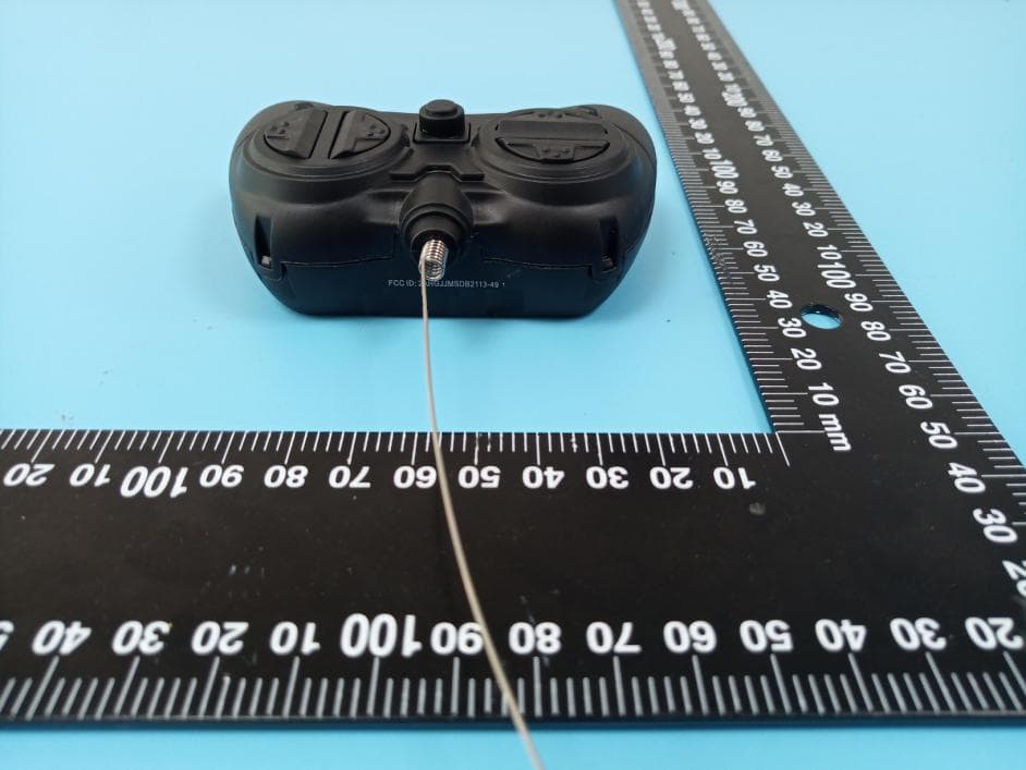
Click to zoom
Application Details
- Equipment Class
- DXX - Part 15 Low Power Communication Device Transmitter
- Date of Grant
- Feb 10, 2020
- Application Purpose
- Original Equipment
- Date of Application
- Feb 10, 2020
- Equipment Note
- RC Sleek Speedboat 49 MHz Remote Controller
- Frequency Range
- 49.86000000 - 49.86000000
- Company
- JM Manufacturing (HK) Ltd.
- Country
- Hong Kong
Documents & Files
Document Text
Text extracted from the exhibit documents filed with the FCC. Open a document above to read the original.
Users Manual
Lightning Strike User Manual Battery installation For Lightning Strike: Turn the latch to the left or right. Remove the screw and open the battery cover. Insert 3x 1.5V AAA Alkaline batteries and close the battery cover. Put the screw back, turn the latch back and lock the battery cover. For Remote Controller: Remove the screw and open the battery cover. Insert 2x 1.5V AA Alkaline batteries and close the battery cover. Put the screw back. Operation procedure Put the Lightning Strike on the water and make sure the frequency docking successfully when the speedboat and the controller are turned on. Use the remote controller to control the Lightning Strike The speedboat will move forward when you press the up button in left side. The speedboat will move backward when you press the down button in left side. The speedboat will turn left and forward when you press the up button in left side and left button in right side. The speedboat will turn right and forward when you press the up button in left side and right button in right side. The speedboat will turn left and backward when you press the down button in left side and left button in right side. The speedboat will turn right and backward when you press the down button in left side and right button in right side. Lightning Strike User Manual Notes: Please make sure the speedboat and remote controller within 8-10meter range. Age Recommendation: 10+ years and adult supervision required. If you do not play the speedboat, you must remove the batteries from both of the remote controller and the speedboat. Packaging includes: Speedboat unit 1pc Remote controller unit 1pc Product dimension: Speedboat unit: 10.5”W x 4.25”D x 3”H Remote controller unit: 3.5”W x 2.5”D x 1.5”H Description: Remote controller batteries: 2 x 1.5V AA Alkaline batteries are not included Lightning Strike batteries: 3 x 1.5V AAA Alkaline batteries are not included Range: 8-10 meters Duration: about 15mins Suitable for children of 10 years old or above Place the Lightning Strike on the water before playing. The Lightning Strike will malfunction if submerged underwater. For safety, do not touch the propeller when the Lightning Strike is on the water. Lightning Strike User Manual This device complies with Part 15 of FCC Rules. Operation is subject to the following two conditions: (1) This device may not cause harmful interference. (2) This device must accept any interference received, including interference that may cause undesired operation. Warning: Changers or modifications to this unit not expressly approved by the party responsible for the compliance could void the user’s authority to operate the equipment. NOTE: This equipment has been tested and found to comply with the limits for a Class B digital device, pursuant to Part, 15 of the FCC Rules. These limits are designed to provide reasonable protection against harmful interference in a residential installation. This equipment generates, uses and can radiate radio frequency energy and, if not installed and used in accordance with the instructions, may cause harmful interference to radio communications. However, there is no guarantee that interference will not occur in a particular installation. If this equipment does cause harmful interference to radio or television reception, which can be determined by turning the equipment off and on, the user is encouraged to try to correct the interference by one or more of the following measures: • Reorient or relocate the receiving antenna. • Increase the separation between the equipment the receiver. • Connect the equipment into an outlet on a circuit different from that to which the receiver is connected. • Consult the dealer or an experienced radio/TV technician for help. RF Warning statement: The device has been evaluated to meet general RF exposure requirement. The device can be used in portable exposure condition without restriction. Conforms to ASTM F963-17
External Photos
EXHIBIT B - EUT EXTERNAL PHOTOGRAPHS
ID Label/Location Info
EXHIBIT A - FCC ID LABEL AND LOCATION FCC ID Label FCC ID Label Location Information The label shown shall be permanently affixed at a conspicuous location on the device and be readily visible to the user at the time purchase (Labeling requirements per 2.925)
Internal Photos
EXHIBIT C - EUT INTERNAL PHOTOGRAPHS Antenna
Operational Description
Circuit Description When the remote control forward, backward, left, right, each function by pressing the corresponding encoding chip function pin high level, after IC internal A/D conversion circuit, reduction of each func tion signal. After reduction each function signal, the IC internal to encode their corresponding instructions, encoded output PC and IC at the same time in the encoding of the output pin part control high frequency oscillation output level work, high-frequency oscillation signal and coding signal in some form of modulated wave modulation circuit, output circuit, the antenna output The working frequency is 49.860MHz.
Test Report
Note: This report must not be used by the customer to claim product certification, approval, or endorsement by A2LA* or any agency of the Federal Government. This report may contain data that are not covered by the A2LA accreditation and are marked with an asterisk “★”. BACL is not responsible for the authenticity of any test data provided by the applicant. Data included from the applicant that may affect test results are marked with an asterisk ’*’. Customer model name, addresses, names, trademarks etc. are not considered data. This report cannot be reproduced except in full, without prior written approval of the Company. Unless otherwise stated the results shown in this test report refer only to the sample(s) tested. This report is valid only with a valid digital signature. The digital signature may be available only under the Adobe software above version 7.0. FCC PART 15.235 TEST REPORT For JM Manufacturing (HK) Ltd. Unit G, 4/F Kaiser Estate, Phase 2, No. 47-53 Man Yue Street, Hung Hom, Kowloon, Hong Kong FCC ID: 2AHGJJMSDB2113-49-1 Report Type: Original Report Product Type: RC Sleek Speedboat 49MHz remote controller Report Number: RSZ191212837-00 Report Date: 2019-12-27 Reviewed By: Kieron Luo RF En gineer Test Laboratory: Bay Area Compliance Laboratories Corp. (Shenzhen) 6/F., West Wing, Third Phase of Wanli Industrial Building, Shihua Road, Futian Free Trade Zone, Shenzhen, Guangdong, China Tel: +86-755-33320018 Fax: +86-755-33320008 www.baclcorp.com.cn Bay Area Compliance Laboratories Corp. (Shenzhen) Report No.: RSZ191212837-00 FCC Part 15.235 Page 2 of 14 TABLE OF CONTENTS GENERAL INFORMATION ....................................................................................................................................... 3 PRODUCT DESCRIPTION FOR EQUIPMENT UNDER TEST (EUT) .................................................................................... 3 OBJECTIVE ................................................................................................................................................................... 3 RELATED SUBMITTAL(S)/GRANT(S) ............................................................................................................................. 3 TEST METHODOLOGY .................................................................................................................................................. 3 TEST FACILITY ............................................................................................................................................................. 3 SYSTEM TEST CONFIGURATION .......................................................................................................................... 4 JUSTIFICATION ............................................................................................................................................................. 4 SPECIAL ACCESSORIES ................................................................................................................................................. 4 EQUIPMENT MODIFICATIONS ....................................................................................................................................... 4 BLOCK DIAGRAM OF TEST SETUP ................................................................................................................................ 4 SUMMARY OF TEST RESULTS ............................................................................................................................... 5 TEST EQUIPMENT LIST ........................................................................................................................................... 6 FCC §15.203 - ANTENNA REQUIREMENT ............................................................................................................. 7 APPLICABLE STANDARD .............................................................................................................................................. 7 ANTENNA CONNECTOR CONSTRUCTION ...................................................................................................................... 7 FCC §15.235(A) & 15.235 (B)&15.209 - RADIATED EMISSIONS AND BAND EDGES .................................. 8 APPLICABLE STANDARD .............................................................................................................................................. 8 MEASUREMENT UNCERTAINTY .................................................................................................................................... 8 EUT SETUP .................................................................................................................................................................. 8 EMI TEST RECEIVER SETUP ......................................................................................................................................... 9 TEST PROCEDURE ........................................................................................................................................................ 9 CORRECTED AMPLITUDE & MARGIN CALCULATION ................................................................................................... 9 TEST RESULTS SUMMARY ............................................................................................................................................ 9 TEST DATA ................................................................................................................................................................ 10 FCC§15.215(C) - 20DB EMISSION BANDWIDTH ................................................................................................ 13 APPLICABLE STANDARD ............................................................................................................................................ 13 TEST PROCEDURE ......................................................................................…
Text truncated - open the document above for the full version.
Contact Information
Applicant
Sam Leung(Merchandising Manager)
Test Firm
Bay Area Compliance Laboratories Corp. (Shenzhen)Well Wang
[email protected]+86 (0) 755 33320018
Technical Specifications
| # | Rule Parts | Frequency Range | Power Output |
|---|---|---|---|
| 1 | 15C | 49.86 MHz - 49.86 MHz | - |
Other Applications from JM Manufacturing (HK) Ltd.
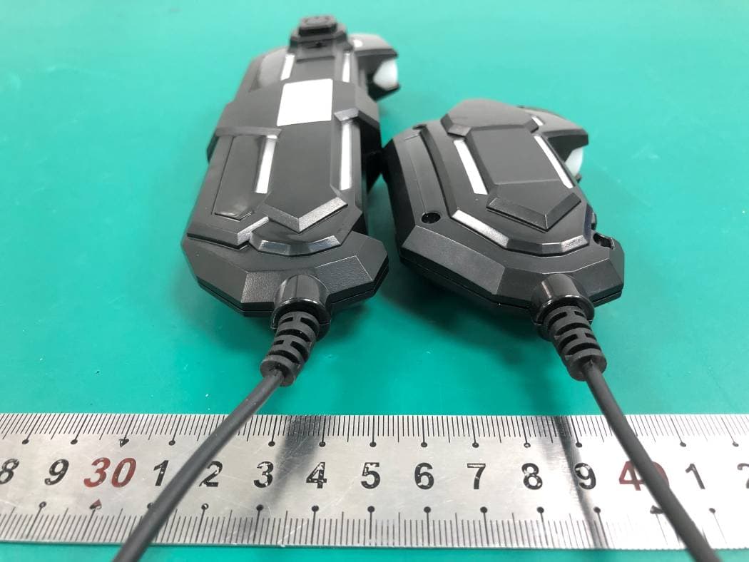
2AHGJJMS251-27-1
Aug 26, 2021PREPACK RC FIGHTING ROBOT
Equipment Class
DXX - Part 15 Low Power Communication Device Transmitter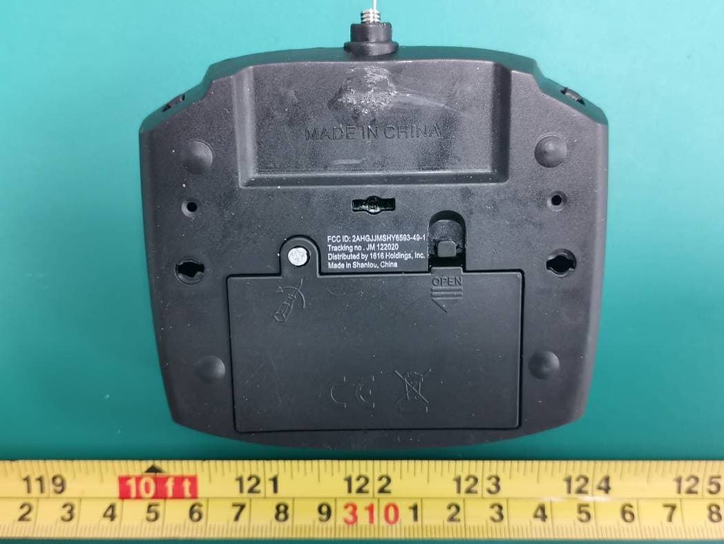
2AHGJJMSHY6593-49-1
Mar 02, 20214CH RC CLIMBER
Equipment Class
DXX - Part 15 Low Power Communication Device Transmitter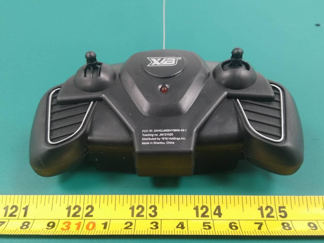
2AHGJJMSHY9805-49-1
Feb 28, 2021RC SPEEDBOAT
Equipment Class
DXX - Part 15 Low Power Communication Device Transmitter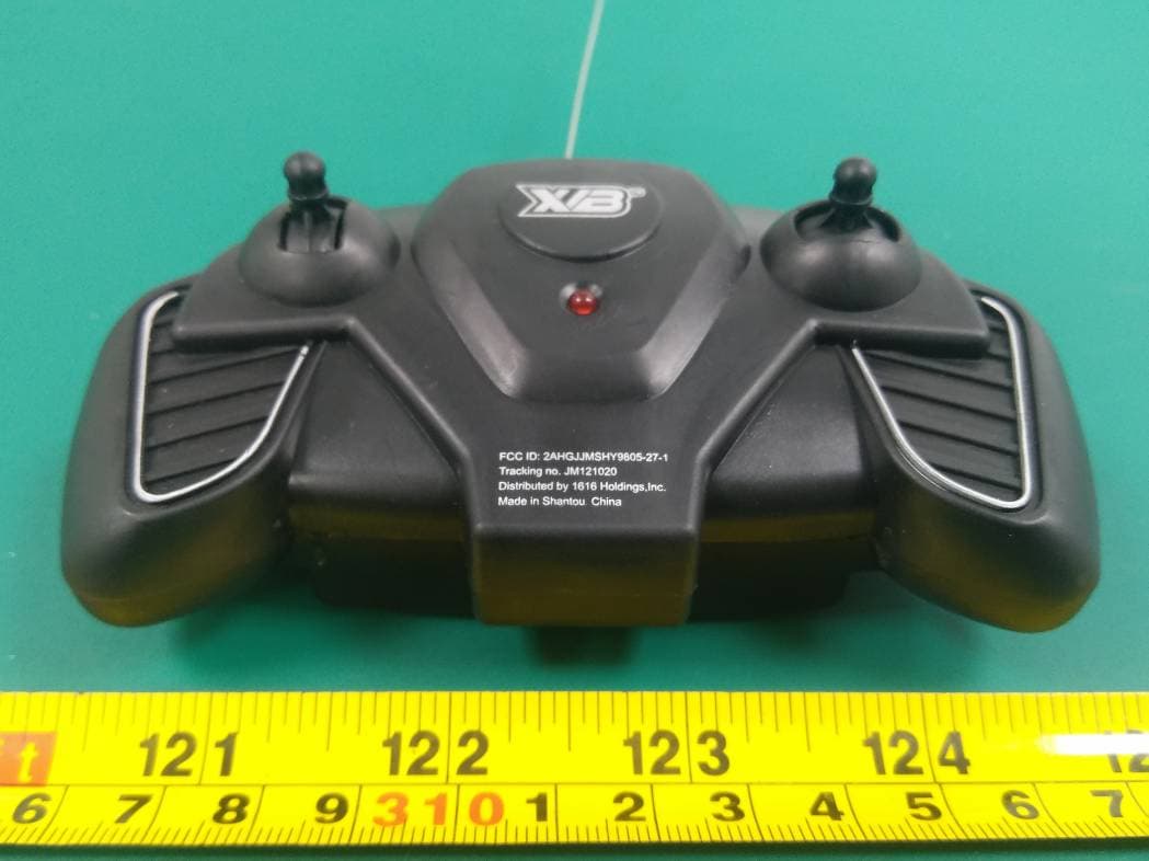
2AHGJJMSHY9805-27-1
Feb 21, 2021RC SPEEDBOAT
Equipment Class
DXX - Part 15 Low Power Communication Device Transmitter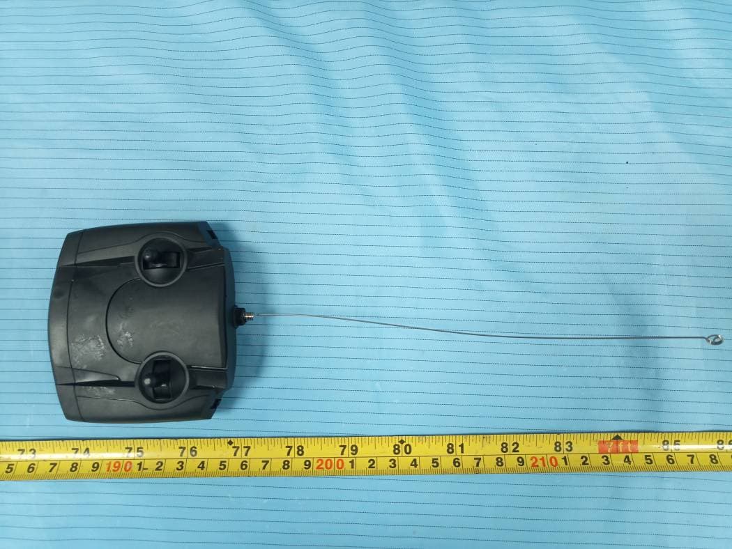
2AHGJJMSHY6593-27-1
Feb 07, 20214 CH RC CLIMBER
Equipment Class
DXX - Part 15 Low Power Communication Device Transmitter