2AHMR-ESP-13Wi-Fi Module
Shenzhen Ai-Thinker Technology co., LTD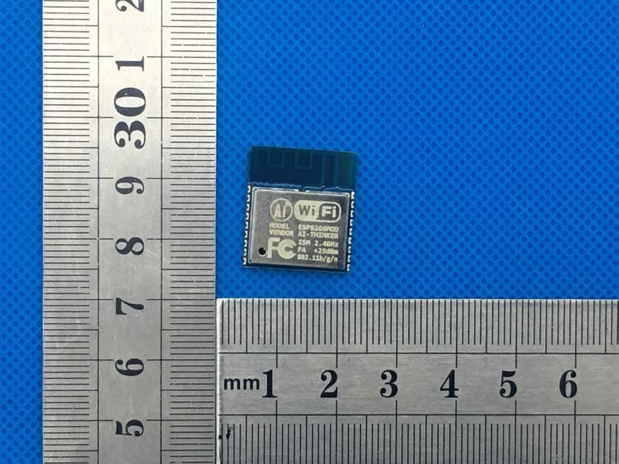
Click to zoom
Application Details
- Equipment Class
- DTS - Digital Transmission System
- Date of Grant
- Jan 16, 2020
- Application Purpose
- Original Equipment
- Date of Application
- Jan 16, 2020
- Equipment Note
- Wi-Fi Module
- Frequency Range
- 2412.00000000 - 2462.00000000
- Country
- China
Documents & Files
Document Text
Text extracted from the exhibit documents filed with the FCC. Open a document above to read the original.
Users Manual
ESP-13 User Manaul 1. Preambles ESP-13 WiFi module is developed by Ai-Thinker Co.,Ltd, core processor ESP8266 in smaller sizes of the module encapsulates Tensilica L106 integrates industry-leading ultra low power 32-bit MCU micro, with the 16-bit short mode, clock speed support 80 MHz, 160 MHz, supports the RTOS, integrated Wi-Fi MAC/BB/RF/PA/LNA, on-board antennas. The module supports standard IEEE802.11 b/g/n agreement, complete TCP/IP protocol stack. Users can use the add modules to an existing device networking, or building a separate network controller. ESP8266 is high integration wireless SOCs, designed for space and power constrained mobile platform designers. It provides unsurpassed ability to embed Wi-Fi capabilities within other systems, or to function as a standalone application, with the lowest cost, and minimal space requirement. Figure 1 ESP8266EX Functional Block Diagram ESP8266EX offers a complete and self-contained Wi-Fi networking solution; it can be used to host the application or to offload Wi-Fi networking functions from another application processor. When ESP8266EX hosts the application, it boots up directly from an external flash. In has integrated cache to improve the performance of the system in such applications. Alternately, serving as a Wi-Fi adapter, wireless internet access can be added to any micro controllerbased design with simple connectivity (SPI/SDIO or I2C/UART interface). ESP8266EX is among the most integrated WiFi chip in the industry; it integrates the antenna switches, RF balun, power amplifier, low noise receive amplifier, filters, power management modules, it requires minimal external circuitry, and the entire solution, including front-end module, is designed to occupy minimal PCB area. ESP8266EX also integrates an enhanced version of Tensilica’s L106 Diamond series 32-bit processor, with on-chip SRAM, besides the Wi-Fi functionalities. ESP8266EX is often integrated with external sensors and other application specific devices through its GPIOs; codes for such applications are provided in examples in the SDK. 2.Features • Support 802.11 b/g/n • Integrated low power 32-bit MCU • Integrated 10-bit ADC • Integrated TCP/IP protocol stack • Integrated TR switch, balun, LNA, power amplifier and matching network • Integrated PLL, regulators, and power management units • Supports antenna diversity • Wi-Fi 2.4 GHz, support WPA/WPA2 • Support STA/AP/STA+AP operation modes • Support Smart Link Function for both Android and iOS devices • SDIO 2.0, (H) SPI, UART, I2C, I2S, IRDA, PWM, GPIO • STBC, 1x1 MIMO, 2x1 MIMO • A- MPDU & A-MSDU aggregation and 0.4s guard interval • Deep sleep power <10uA, Power down leakage current < 5uA • Wake up and transmit packets in < 2ms • Standby power consumption of < 1.0mW (DTIM3) • Onboard 3dBi gain PCB antenna • Operating temperature range -20°C~+85°C 3.Parameters Table 1 below describes the major parameters. Table 1 Parameters Categories Items Values WiFi Paramters WiFi Protocles 802.11 b/g/n Frequency Range 2.4GHz-2.5GHz (2400M-2483.5M) Transmit power 802.11b: +16dBm(±2dBm) 802.11g: +14dBm(±2dBm) 802.11n: +13dBm(±2dBm) Receiver sensitivity 802.11b: -91dBm(11Mbps) 802.11g: -75dBm(54Mbps) 802.11n: -72dBm(MCS7) Hardware Paramaters Peripheral Bus UART/HSPI/I2C/I2S/Ir Remote Contorl GPIO/PWM Operating Voltage 3.3V Operating Current Average value: 80mA Operating Temperature Range -20°C~+85°C Ambient Temperature Range Normal temperature Package Size 18mm*20mm*2.8mm External Interface N/A Software Parameters Wi-Fi mode station/softAP/SoftAP+station Security WPA/WPA2 Encryption WEP/TKIP/AES Firmware Upgrade UART Download / OTA (via network) / download and write firmware via host Ssoftware Development Supports Cloud Server Development / SDK for custom firmware development Network Protocols IPv4, TCP/UDP/HTTP/FTP User Configuration AT Instruction Set, Cloud Server, Android/iOS APP FCC WARNING STATEMENT Changes or modifications not expressly approved by the party responsible for compliance could void the user’s authority to operate the equipment. This equipment has been tested and found to comply with the limits for a Class B digital device, pursuant to Part 15 of the FCC Rules. These limits are designed to provide reasonable protection against harmful interference in a residential installation. This equipment generates uses and can radiate radio frequency energy and, if not installed and used in accordance with the instructions, may cause harmful interference to radio communications. However, there is no guarantee that interference will not occur in a particular installation. If this equipment does cause harmful interference to radio or television reception, which can be determined by turning the equipment off and on, the user is encouraged to try to correct the interference by one or more of the following measures: -- Reorient or relocate the receiving antenna. -- Increase the separation between the equipment and receiver. -- Connect the equipment into an outlet on a circuit different from that to which the receiver is connected. -- Consult the dealer or an experienced radio/TV technician for help. This device complies with Part 15 of the FCC Rules. Operation is subject to the following two conditions: (1) This device may not cause harmful interference, and (2) This device must accept any interference received, including interference that may cause undesired operation. FCC Radiation Exposure Statement The modular can be installed or integrated in mobile or fix devices only. This modular complies with FCC RF radiation exposure limits set forth for an uncontrolled environment. This transmitter must not be co-located or operating in conjunction with any other antenna or transmitter. This modular must be installed and operated with a minimum distance of 20 cm between the radiator and user body. If the FCC identification number is not visible when the module is installed inside another device, then the outside of the device into which the…
Text truncated - open the document above for the full version.
Cover Letter(s)
Date: Dec. 30, 2019 Equipment Autorisation Division Federal Communications Commission 7435 Oakland Mills Road Columbia, MD 21046 FCC ID: 2AHMR-ESP-13 Product Name: Wi-Fi Module Request for Confidentiality Pursuant to Sections 0.457 and 0.459 of the commission’s rules, we hereby request that the following documents be held confidential: (List here the documents for which you are seeking confidentiality – for example ...) • Schematics • Block diagram • Operation description These materials contain trade secrets and proprietary information and are not customarily released to the public. The public disclosure of this information might be harmful to the company and provide unjustified benefits to our competitors. <Signature> Name: Su Facheng Title: Engineer Company: Shenzhen Ai-Thinker Technology Co., Ltd
Cover Letter(s)
Date: Dec. 30, 2019 Federal Communications Commission Authorization & Evaluation Division 7345 Oakland Mills Road Columbia, Maryland 21046 RE: LETTER OF AGENT AUTHORIZATION To Whom It May Concern: We, the undersigned, hereby authorize Compliance Testing, LLC to act on our behalf in all matters relating to application for equipment authorization, including the signing of all documents relating to these matters. We also hereby certify that no party to the application authorized hereunder is subject to the denial of benefits, including FCC benefits, pursuant to Section 5301 of the Anti-Drug Abuse Act of 1988, 21 U.S.C.853(a). Sincerely, <Signature> Name: Su Facheng Title: Engineer Company: Shenzhen Ai-Thinker Technology Co., Ltd
Cover Letter(s)
Date: Dec. 30, 2019 Federal Communications Commission Authorization & Evaluation Division 7345 Oakland Mills Road Columbia, Maryland 21046 Authority to Act as Agent On our behalf, I appoint Shenzhen CTB Testing Technology Co., Ltd. Add: Floor 1&2, Building A, No. 26 of Xinhe Road, Xinqiao Community, Xinqiao Street, Baoan District, Shenzhen, Guangdong, China to act as our agent in the preparation of this application for equipment certification. I certify that submitted documents properly describe the device or system for which equipment certification is sought. I also certify that each unit manufactured, imported or marketed, as defined in the Federal Communications Commission’s regulations will have affixed to it a label identical to that submitted for approval with this application. For instances where our authorized agent signs the application for certification on our behalf, I acknowledge that all responsibility for complying with the terms and conditions for certification, still resides with Shenzhen Ai-Thinker Technology Co., Ltd Add: 6/F, Block C2, Huafeng Industrial Park, Hangcheng Road, Baoan district, Shenzhen China <Signature> Name: Su Facheng Title: Engineer Company: Shenzhen Ai-Thinker Technology Co., Ltd
Cover Letter(s)
Single Modular approval Declaration letter We, Shenzhen Ai-Thinker Technology Co., Ltd apply Single modular approval for Product Name: Wi-Fi Module MODEL No.: ESP-13 FCC ID: 2AHMR-ESP-13 According to 996369 D01 Module Equip Auth Guide v01r04 and 15.212 requirement: 1)The radio elements must have the radio frequency circuitry shielded. Physical components and tuning capacitor(s) may be located external to the shield, but must beon the module assembly; A nswer :Yes ; shielded for both side 2)The module must have buffered modulation/data inputs to ensure that the device will comply with Part 15 requirements with any type of input signal; Answer :Yes ;All inputs to the modules are buffered through logic or microprocessor inputs. 3)The modular transmitter must have its own power supply regulation. A nswer :Yes ;A low drop out regulator is used for modular power supply regulation. 4)The module must contain a permanently attached antenna, or contain a unique antenna connector, and be marketed and operated only with specific antenna(s), per Sections 15.203, 15.204(b), 15.204(c), 15.212(a), 2.929(b); Answer :Yes ;Device is equipped with Integral PCB antenna. (5)The module must demonstrate compliance in a stand-alone configuration; Answer :Yes,distance between modular and all AEs are longer than 10cm ,refer to setup photo. ( 6)The module must be labelled with its permanently affixed FCC ID label, or use an electronic display (See KDB Publication 784748 about labelling requirements); Answer :Yes ;The modular has a permanent fixed label, and below statement was listed in the User Manual;The host device must be labeled to display the FCC ID of the module Contains FCC ID: 2AHMR-ESP-13 (7)The module must comply with all specific rules applicable to the transmitter including all the conditions provided in the integration instructions by the grantee; Answer :Yes ;The module comply with all specific rules applicable to the transmitter including all the conditions provided in the integration instructions by the grantee, Refer to test report and user manual . (8)The module must comply with RF exposure requirements Answer :Yes ;Transmitter meets MPE calculation of 47 CFR 1.1307 . Refer to MPE Reports and Refer to modular installation manual <Signature> Name: Su Facheng Title: Engineer Company: Shenzhen Ai-Thinker Technology Co., Ltd
External Photos
M/N: ESP-13 M/N: ESP-13 M/N: ESP-13
ID Label/Location Info
FCC ID LABEL: Label Location: FCC ID: 2AHMR-ESP-13 Long:0.8cm Width:0.2cm
Internal Photos
M/N: ESP-13 PCB A N T.
RF Exposure Info
FCC §15.247 (i), §2.1091 – RF Exposure FCC ID: 2AHMR-ESP-13 Applied procedures / limit According to FCC §15.247(i) and §1.1307(b)(1), systems operating under the provisions of this section shall be operated in a manner that ensures that the public is not exposed to radio frequency energy level in excess of the Commission’s guidelines. Limits for Occupational / Controlled Exposure Frequency Range (MHz) Electric Field Strength (E) (V/m) Magnetic Field Strength (H) (A/m) Power Density (S) (mW/ cm 2 ) Averaging Time |E| 2 ,|H| 2 or S (minutes) 0.3-3.0 614 1.63 (100)* 6 3.0-30 1842 / f 4.89 / f (900 / f)* 6 30-300 61.4 0.163 1.0 6 300-1500 F/300 6 1500-100,000 5 6 Note: ƒ is frequency in MHz * = Power density limit is applicable at frequencies greater than 100 MHz Limits for General Population / Uncontrolled Exposure Frequency Range (MHz) Electric Field Strength (E) (V/m) Magnetic Field Strength (H) (A/m) Power Density (S) (mW/ cm 2 ) Averaging Time |E| 2 ,|H| 2 or S (minutes) 0.3-1.34 614 1.63 (100)* 30 1.34-30 824/f 2.19/f (180/f)* 30 30-300 27.5 0.073 0.2 30 300-1500 F/1500 30 1500-100,000 1.0 30 Note: f = frequency in MHz * = Plane-wave equivalent power density MPE PREDICTION Predication of MPE limit at a given distance, Equation from OET Bulletin 65, Edition 97-01 Where: S = power density P = power input to antenna G = power gain of the antenna in the direction of interest relative to an isotropic radiator R = distance to the center of radiation of the antenna,R=20cm Test Result of RF Exposure Evaluation Target power W/ tolerance (dBm) Max tune up power tolerance (dBm) Total Output power to antenna (mW) Antenna Gain(dBi) Total Power Density at R=20cm (mW/cm 2 ) 802.11b 16±2.0 18 63.10 3 (2.00) 0.025058 Max PK Outpout power (dBm) Output power(mW) Antenna Gain (dBi) MPE(mW/cm2) Limit (mW/cm2) Result 802.11b 15.006 31.67 3 (2.00) 0.012576 1 PASS
Test Report
Report No.: HK1911293052-1E TEST REPORT Test report On Behalf of Shenzhen Ai-Thinker Technology Co., Ltd. For Wi-Fi Module Model No.: ESP-13 FCC ID :2AHMR-ESP-13 Prepared for : Shenzhen Ai-Thinker Technology Co., Ltd. 6/F, Block C2, Huafeng Industrial Park, Hangcheng Road, Baoan district, Shenzhen China Prepared By : Shenzhen HUAK Testing Technology Co., Ltd. 1F, B2 Building, Junfeng Zhongcheng Zhizao Innovation Park, Fuhai Street, Bao'an District, Shenzhen City, China Date of Test: Nov. 26, 2019 ~ Dec. 12, 2019 Date of Report: Dec. 12, 2019 Report Number: HK1911293052-1E Page 1 of 54 Report No.: HK1911293052-1E TEST RESULT CERTIFICATION Applicant’s name .................. : Shenzhen Ai-Thinker Technology Co., Ltd. Address ................................... : 6/F, Block C2, Huafeng Industrial Park, Hangcheng Road, Baoan district, Shenzhen China Manufacture's Name ............ : Shenzhen Ai-Thinker Technology Co., Ltd. Address ................................... : 6/F, Block C2, Huafeng Industrial Park, Hangcheng Road, Baoan district, Shenzhen China Product description Trade Mark: N/A Product name ........................... : Wi-Fi Module Model and/or type reference . : ESP-13 Standards .............................. : FCC Rules and Regulations Part 15 Subpart C Section 15.247 ANSI C63.10: 2013 This publication may be reproduced in whole or in part for non-commercial purposes as long as the Shenzhen HUAK Testing Technology Co., Ltd. is acknowledged as copyright owner and source of the material. Shenzhen HUAK Testing Technology Co., Ltd. takes no responsibility for and will not assume liability for damages resulting from the reader's interpretation of the reproduced material due to its placement and context. Date of Test .............................................. : Date (s) of performance of tests .............. : Nov. 26, 2019 ~ Dec. 12, 2019 Date of Issue ............................................. : Dec. 12, 2019 Test Result ................................................. : Pass Testing Engineer : (Gary Qian) Technical Manager : (Eden Hu) Authorized Signatory : (Jason Zhou) Page 2 of 54 Report No.: HK1911293052-1E TABLE OF CONTENTS 1. Test Result Summary .................................................................................. 4 1.1. TEST PROCEDURES AND RESULTS ............................................................................................. 4 1.2. TEST FACILITY ................................................................................................................................ 4 1.3. MEASUREMENT UNCERTAINTY ............................................................................................................. 5 2. EUT Description ........................................................................................... 6 2.1. GENERAL DESCRIPTION OF EUT .................................................................................................. 6 2.2. CARRIER FREQUENCY OF CHANNELS.................................................................................................... 7 2.3. OPERATION OF EUT DURING TESTING ................................................................................................... 7 2.4. DESCRIPTION OF TEST SETUP ..................................................................................................... 7 3. Genera Information ..................................................................................... 8 3.1. TEST ENVIRONMENT AND MODE ............................................................................................................ 8 3.2. DESCRIPTION OF SUPPORT UNITS ........................................................................................................ 9 4. Test Results and Measurement Data ....................................................... 10 4.1. CONDUCTED EMISSION ...................................................................................................................... 10 4.2. MAXIMUM CONDUCTED OUTPUT POWER ............................................................................................. 14 4.3. EMISSION BANDWIDTH ....................................................................................................................... 16 4.4. POWER SPECTRAL DENSITY............................................................................................................... 21 4.5. CONDUCTED BAND EDGE AND SPURIOUS EMISSION MEASUREMENT .................................................... 26 4.6. RADIATED SPURIOUS EMISSION MEASUREMENT .................................................................................. 31 4.7. ANTENNA REQUIREMENT............................................................................................................ 52 4.8. PHOTOGRAPH OF TEST ............................................................................................................... 53 Page 3 of 54 Report No.: HK1911293052-1E 1. Test Result Summary 1.1. TEST PROCEDURES AND RESULTS Requirement CFR 47 Section Result Antenna requirement §15.203/§15.247 (c) PASS AC Power Line Conducted Emission §15.207 PASS Conducted Peak Output Power §15.247 (b)(3) §2.1046 PASS 6dB Emission Bandwidth §15.247 (a)(2) §2.1049 PASS Power Spectral Density §15.247 (e) PASS Band Edge 1§5.247(d) §2.1051, §2.1057 PASS Spurious Emission §15.205/§15.209 §2.1053, §2.1057 PASS Note: 1. PASS: Test item meets the requirement. 2. Fail: Test item does not meet the requirement. 3. N/A: Test case does not apply to the test object. 4. The test result judgment is decided by the limit of test standard. 1.2. TEST FACILITY Te s t F i r m : Shenzhen HUAK Testing Technology Co., Ltd. Address 1F, B2 Building, Junfeng Zhongcheng Zhizao Innovation Park, Fuhai Street, Bao'an District, Shenzhen City, China Page 4 of 54 Report No.: HK1911293052-1E 1.3. Measurement Uncertainty The reported uncertainty of measurement y ± U, where expended uncertainty U is based on a standard …
Text truncated - open the document above for the full version.
Test Setup Photos
M/N: ESP-13 Radiated Emission test M/N: ESP-13 Conducted Emission test
Contact Information
Applicant
Mars Ma(Director of Marketing)
Test Firm
Shenzhen HUAK Testing Technology Co., Ltd.Jason Zhou
[email protected]+86-755-23029901
Technical Specifications
| # | Rule Parts | Frequency Range | Power Output |
|---|---|---|---|
| 1 | 15C | 2.41 GHz - 2.46 GHz | 31.70 mW |
Other Applications from Shenzhen Ai-Thinker Technology co., LTD
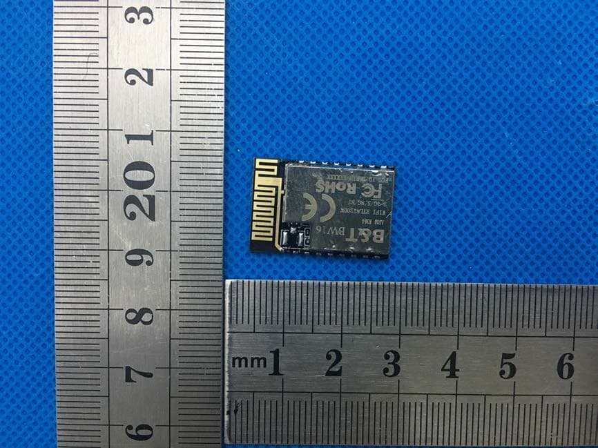
2AHMR-BW16
Feb 17, 2020Wi-Fi and BT SoC Module
Equipment Class
NII - Unlicensed National Information Infrastructure TX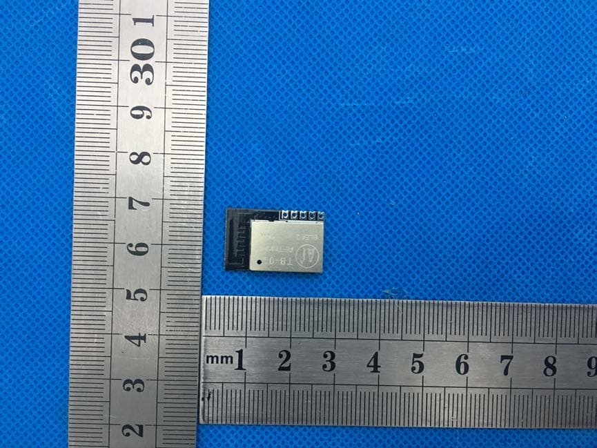
2AHMR-TB-01
Jan 16, 2020Bluetooth module
Equipment Class
DTS - Digital Transmission System