2AHW7-QINGREMOTEThe Remote Control of Intelligent Gimbal for Camera
Guilin Feiyu Technology Incorporated Company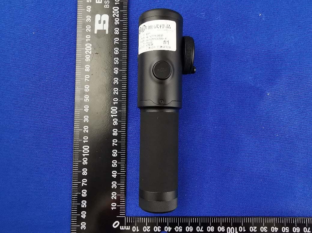
Click to zoom
Application Details
- Equipment Class
- DTS - Digital Transmission System
- Date of Grant
- Mar 18, 2020
- Application Purpose
- Original Equipment
- Date of Application
- Mar 18, 2020
- Equipment Note
- The Remote Control of Intelligent Gimbal for Camera
- Frequency Range
- 2410.00000000 - 2470.00000000
- Country
- China
Documents & Files
Document Text
Text extracted from the exhibit documents filed with the FCC. Open a document above to read the original.
Users Manual
Intelligent Gimbal for Camera Instructions EN V1.0 2 Catalogue 1. Overview ..................................................................2 2. Start to Use ...............................................................4 2.1 Charging.................................................................................4 2.2 Unlock/Lock ...........................................................................5 2.3 Battery Installation ..................................................................5 2.4 Camera Installation and Balance ................................................6 2.5 Power On/Off ........................................................................8 3. Function & Operation ...................................................9 3.1 Function/Modes Introduction ...................................................9 3.2 Function Operation of Remote Control .......................................12 3.3 Remote Control Touch Screen ...................................................16 3.4 Modes Setting ........................................................................17 3.5 Gimbal Initialization ..................................................................21 4. Accessories ...............................................................22 4.1 Brushless Follow Focus (AKF II) ...................................................22 4.2 Wireless MIC Kit .....................................................................23 5. Specifications ............................................................25 Compatible Cameras for Reference .................................26 Disclaimer .....................................................................28 www.feiyu-tech.com12 QING is a professional gimbal for DSLR/mirrorless camera. It is compatible with popular DSLR camera on the market. It is available to install on the tripod or other carrier to extend its shooting function. It has a oversized touch screen on remote control, allows users to switch work modes, control rotating direction and set up parameters on it directly and visibly. Users can also control camera's follow focus and zooming after connecting camera to QING via cable. Suggestion Feiyu Qing includes below information, please read the information before using the gimbal: 1. Quick start guide 2. Online instruction 3. Tutorial The tutorial videos can be watched at FeiyuTech official website https://www.feiyu-tech.com/play/ or scan the QR code. www.feiyu-tech.com2 1. Overview * The product is NOT included the camera. www.feiyu-tech.com32 www.feiyu-tech.com4 2. Start to Use TIPS · Please install the camera and balance it before power on the gimbal. · Please do not touch tilt motor and gears to avoid gripping. · When the battery is low, please charge the battery. · When not in use, power off the gimbal and then remove the batteries. 2.1 Charging Please fully charge the dedicated battery before power on the gimbal for the first time. Please choose the suitable charger when quickly charging. 2.1.1 Charging for the Gimbal Using USB2.0 to Type-C cable to charge the dedicated battery, support 5V/3A input. Battery Indicator: All the 3 indicators turn on when battery is full Function Indicator: quickly flashing: Low battery and please charge in time slowly flashing: Pan mode constant on: Lock mode www.feiyu-tech.com54 2.1.2 Charging for the Remote Control Using USB2.0 to Micro cable to charge the remote control, support 5V/3A input. 2.2 Unlock/Lock There is a position lock on the tilt axis, which is convenient for locking the position, installation, storage. Unlock the gimbal before powering on it. 2.3 Battery Installation Please fully charge the dedicated battery before power on the gimbal for the first time. Install the battery: Push the battery in along the slot ①, and after that, the battery lock ② will rebound to prevent battery from falling. Remove the battery: Unlock the battery lock ② and pull the battery out. www.feiyu-tech.com6 ① ② 2.4 Camera Installation and Balance TIPS · Make sure the battery and memory card are loaded before camera installation. · Before balancing the gimbal, the lens cover should be removed from the camera and the memory card needs to be inserted to the camera to complete all the cable connections to ensure that the camera is ready for shooting. · During balancing the gimbal, make sure the camera is power off and the gimbal is turned off. · If add accessories after the balance is completed, please re-balance. In order to get ideal shooting, please balance the gimbal before using. And the gimbal with perfect balance will have longer battery life. Step 1: Keep the gimbal horizontal as the figure shows, then lock the position lock ①. www.feiyu-tech.com76 Step 2: Mount camera on ARCA quick release plate ②, and tighten it. Step 3: Install the ARCA quick release plate on the quick release plate, and tighten the ARCA quick release plate safety lock ③. Install the lens support frame ④ and tighten the thumb screw ⑤ to hold the lens firmly. Step 4: Unlock the position lock ①, and loose the thumb screw ⑥. Slide the slide arm ⑦ to balance, and tighten the thumb screw ⑥ after the balancing is completed. If the camera can stay stable after moving your hand away, which means balanced. www.feiyu-tech.com8 2.5 Power On/Off Please release the tilt motor lock before powering on. Please do not touch tilt motor and gears to avoid gripping. Steps: (1) Gimbal: Install the dedicated battery and long press the power button and release it when the battery indicator and function indicator turn on together and hear the tone. Long press again to power off. (2) Remote Control: Long press the power button, release it when the touch screen shows . Long press again to power off. www.feiyu-tech.com98 3. Function & Operation 3.1 Function/Modes Introduction ① Pan Mode (Default mode) When attached on the other equipment, the tilt direction is fixed, and the camera direction moves according to the rotation of the equipment. ②…
Text truncated - open the document above for the full version.
External Photos
Annex No.: BL-SZ19C0301-AW 1 / 3 EUT EXTERNAL PHOTOS FRONT VIEW OF EUT REAR VIEW OF EUT Annex No.: BL-SZ19C0301-AW 2 / 3 LEFT SIDE VIEW OF EUT RIGHT SIDE OF EUT Annex No.: BL-SZ19C0301-AW 3 / 3 TOP VIEW OF EUT BOTTOM VIEW OF EUT
Internal Photos
Annex No.: BL-SZ19C0301-AI 1 / 4 EUT INTERNAL PHOTOS EUT UNCOVER VIEW EUT UNCOVER VIEW Annex No.: BL-SZ19C0301-AI 2 / 4 MAIN BOARD TOP VIEW MAIN BOARD REAR VIEW Annex No.: BL-SZ19C0301-AI 3 / 4 MAIN BOARD TOP VIEW MAIN BOARD REAR VIEW PCB Antenna RF Chip Annex No.: BL-SZ19C0301-AI 4 / 4 Battery Photo (FRONT) Battery Photo (REAR)
Operational Description
version01 Guilin Feiyu Technology Incorporated Company Declaration concerning Antenna Specification It is hereby declared that the product Model No.: Qingremote FCC ID: 2AHW7- QINGREMOTE fulfills the requirement in FCC test relating to the antenna type. The device specified above confirms to the FCC recommendations for internal antenna type(s) described below: Model No. of antenna: N/A Type of antenna: PCB PIFA Antenna Gain of the antenna: 1.77 dBi Frequency range: 2410-2470 MHz The mounting of the antenna is fixed to the radio module and no other antenna should be used. Company name: Guilin Feiyu Technology Incorporated Company Address: 3rd Floor,B,Guilin Electric Valley,Innovation Building Information Industry Park,ChaoYang Road City: Guilin ZIP / Postal code: Country: China Place: Guilin Date: 2020-03-18 Signature:
RF Exposure Info
RF Exposure Evaluation for FCC ID: 2AHW7‐QINGREMOTE Refer user manual this device is a The Remote Control of Intelligent Gimbal for Camera, and this device was designed used in portable devices that the minimum distance between human’s body is 5mm. Based on the 47CFR 2.1093, this device belongs to portable device. The definition of the category as following: Portable Derives: CFR Title 47 §2.1093(b) (b) For purposes of this section, a portable device is defined as a transmitting device designed to be used so that the radiating structure(s) of the device is/are within 20 centimeters of the body of the user. FCC KDB 447498 D01 General RF Exposure Guidance v06 Limit Unless specifically required by the published RF exposure KDB procedures, standalone 1‐g head or body and 10‐g extremity SAR evaluation for general population exposure conditions, by measurement or numerical simulation, is not required when the corresponding SAR Test Exclusion Threshold condition, listed below, is satisfied. These test exclusion conditions are based on source‐ based time‐averaged maximum conducted output power of the RF channel requiring evaluation, adjusted for tune‐up tolerance, and the minimum test separation distance required for the exposure conditions. The minimum test separation distance is determined by the smallest distance from the antenna and radiating structures or outer surface of the device, according to the host form factor, exposure conditions and platform requirements, to any part of the body or extremity of a user or bystander. The 1‐g and 10‐g SAR test exclusion thresholds for 100 MHz to 6 GHz at test separation distances ≤ 50 mm are determined by: [(max. power of channel, including tune‐up tolerance, mW) / (min. test separation distance, mm)] · [√f(GHz) ] ≤ 3.0 for 1‐g SAR and ≤ 7.5 for 10‐g extremity SAR Where • f (GHz) is the RF channel transmit frequency in GHz • Power and distance are rounded to the nearest mW and mm before calculation • The result is rounded to one decimal place for comparison The test exclusions are applicable only when the minimum test separation distance is ≤ 50 mm and for transmission frequencies between 100 MHz and 6 GHz. When the minimum test separation distance is < 5 mm, a distance of 5 mm is applied to determine SAR test exclusion. Test data 2.4G ISM Band (GFSK modulation) Mode GFSK Low Channel Middle Channel High Channel Peak Power (dBm) 1.37 1.62 1.07 Note: This report listed the worst case peak power value, please refer to RF test report for more details. Turn-up power Mode Range (dBm) 2.4G ISM Band (GFSK modulation) 1.00-2.00 FCC exclusion condition= [1.58 mW/5 mm] · [√2.44 GHz] = 0.49 < 3.0 RF Exposure Evaluation Result: Pass Note: More power data, Please refer to the RF report.
Test Report
Report No.: BL-SZ19C0301-601 2 / 52 Revision History Version Issue Date Revisions Content Rev. 01 Mar. 13, 2020 Initial Issue Rev. 02 Mar. 19, 2020 Added note for all modes have been tested and normal link mode is worst TABLE OF CONTENTS 1 ADMINISTRATIVE DATA (GENERAL INFORMATION) .......................................................................... 5 1.1 Identification of the Testing Laboratory ....................................................................................... 5 1.2 Identification of the Responsible Testing Location ...................................................................... 5 1.3 Laboratory Condition ................................................................................................................... 5 1.4 Announce .................................................................................................................................... 5 2 PRODUCT INFORMATION ...................................................................................................................... 6 2.1 Applicant Information ................................................................................................................... 6 2.2 Manufacturer Information ............................................................................................................ 6 2.3 Factory Information ..................................................................................................................... 6 2.4 General Description for Equipment under Test (EUT) ................................................................ 6 2.5 Technical Information .................................................................................................................. 7 2.6 Additional Instructions ................................................................................................................. 8 3 SUMMARY OF TEST RESULTS .............................................................................................................. 9 3.1 Test Standards ............................................................................................................................ 9 3.2 Verdict ......................................................................................................................................... 9 4 GENERAL TEST CONFIGURATIONS ................................................................................................... 10 4.1 Test Environments .................................................................................................................... 10 4.2 Test Equipment List ................................................................................................................... 10 4.3 Measurement Uncertainty ......................................................................................................... 11 4.4 Description of Test Setup .......................................................................................................... 12 4.4.1 For Antenna Port Test ............................................................................................................... 12 4.4.2 For AC Power Supply Port Test ................................................................................................ 12 4.4.3 For Radiated Test (Below 30 MHz) ........................................................................................... 13 4.4.4 For Radiated Test (30 MHz-1 GHz) .......................................................................................... 13 4.4.5 For Radiated Test (Above 1 GHz) ............................................................................................. 14 4.5 Measurement Results Explanation Example ............................................................................. 15 Report No.: BL-SZ19C0301-601 3 / 52 4.5.1 For conducted test items: .......................................................................................................... 15 4.5.2 For radiated band edges and spurious emission test: ............................................................... 15 5 TEST ITEMS ........................................................................................................................................... 16 5.1 Antenna Requirements .............................................................................................................. 16 5.1.1 Relevant Standards ................................................................................................................... 16 5.1.2 Antenna Anti-Replacement Construction .................................................................................. 16 5.1.3 Antenna Gain ............................................................................................................................ 16 5.2 Output Power ............................................................................................................................ 17 5.2.1 Test Limit ................................................................................................................................... 17 5.2.2 Test Setup ................................................................................................................................. 17 5.2.3 Test Procedure .......................................................................................................................... 17 5.2.4 Test Result ................................................................................................................................ 18 5.3 Occupied Bandwidth ................................................................................................................. 19 5.3.1 Limit ........................................................................................................................................... 19 5.3.2 Test Setup ..............................................................................................…
Text truncated - open the document above for the full version.
Test Setup Photos
Annex No.: BL-SZ19C0301-AR TEST SETUP PHOTOS 1 Radiated Test Photo Below 30 MHz 30 MHz-1 GHz Annex No.: BL-SZ19C0301-AR Close-Up Above 1GHz Annex No.: BL-SZ19C0301-AR Close-Up 2 Conducted Emissions Test Photo 1 Annex No.: BL-SZ19C0301-AR Test Photo 2 3 Conducted Test Photo Conducted Test
Contact Information
Applicant
Alex Wang
Test Firm
Shenzhen BALUN Technology Co., Ltd.Hanson Lin
[email protected]86-755-66833830
Technical Specifications
| # | Rule Parts | Frequency Range | Power Output |
|---|---|---|---|
| 1 | 15C | 2.41 GHz - 2.47 GHz | 1.50 mW |
Other Applications from Guilin Feiyu Technology Incorporated Company
2AHW7-FEIYUX10
Jan 29, 2026Feiyu X10 AI Tracking Handheld Gimbal for Smartphone
Equipment Class
DTS - Digital Transmission System
2AHW7-FEIYUVB4
Sep 04, 2023Feiyu VB 4 3-Axis Handheld Gimbal for Smartphone
Equipment Class
DTS - Digital Transmission System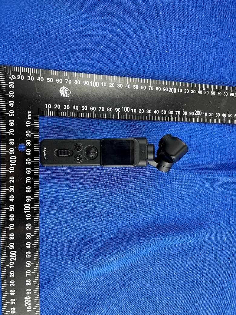
2AHW7-FEIYUVCAM3SRH
May 29, 2023Remote Handle for Feiyu Pocket 3
Equipment Class
DTS - Digital Transmission System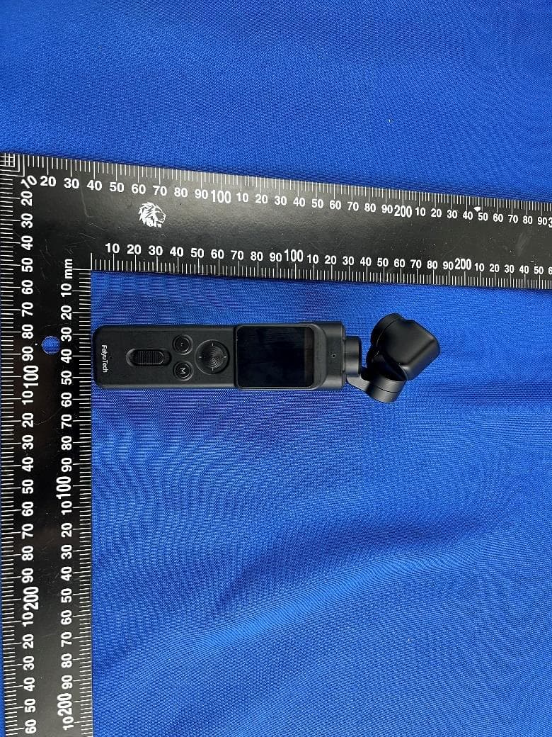
2AHW7-FEIYUVCAM3S
May 29, 2023Feiyu Pocket 3 Stabilized Camera
Equipment Class
DTS - Digital Transmission System
2AHW7-VB4SE
May 07, 2023Feiyu VB 4SE 3-Axis Handheld Gimbal for Smartphone
Equipment Class
DTS - Digital Transmission System