2AHXJ-M1017PRO SENSOR
Mopeka Products, LLC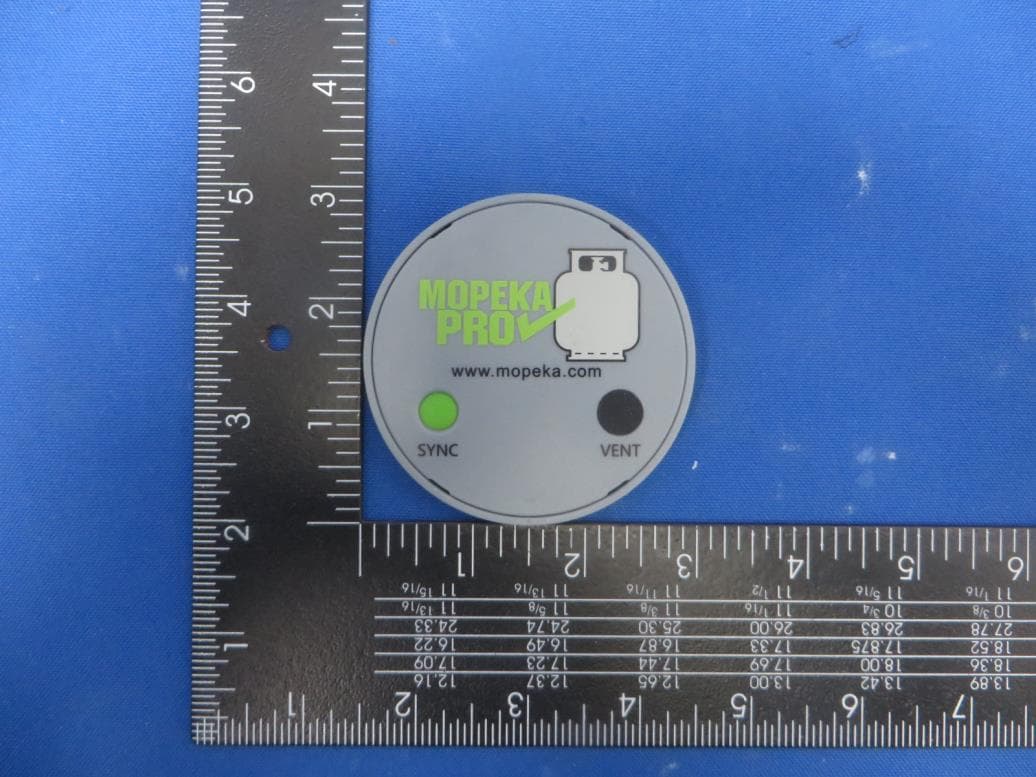
Click to zoom
Application Details
- Equipment Class
- DTS - Digital Transmission System
- Date of Grant
- Jan 10, 2021
- Application Purpose
- Original Equipment
- Date of Application
- Jan 10, 2021
- Equipment Note
- PRO SENSOR
- Frequency Range
- 2402.00000000 - 2480.00000000
- Company
- Mopeka Products, LLC
- Country
- United States
Documents & Files
Document Text
Text extracted from the exhibit documents filed with the FCC. Open a document above to read the original.
Users Manual
www.mopeka.com Page 1 of 14 M200004E Pro Sensor Models M1017--- (Propane) INTENDED USE OF THE M1017 SENSOR IS TO MEASURE THE AMOUNT OF LIQUID PROPANE INSIDE A PROPANE TANK MEETING THE SPECIFATIONS BELOW, UNDER THE CONDITIONS LISTED BELOW. THIS DEVICE IS INTENDED FOR OUTDOOR USE ONLY. WARNING USE OF THIS DEVICE IN A MANNER OTHER THAN STATED IN THIS MANUAL, MAY RESULT IN IMPAIRMENT OF THE DESIGNED SAFETY PROTECTION AND THUS AN UNSAFE CONDITION. SPECIFICATIONS MEASUREMENT METHOD Ultrasonic FLUID Propane TANK TYPES Steel or Aluminum Not intended for use on composite cylinders. TANK SIZES Horizontal and Vertical Tanks Up to 48-inch fluid height Envelope Dimensions 73 mm Diameter x 7.3 mm Thickness (2.87 x 0.29 inches) Mounting location Tank Bottom Steel Tanks use magnet version Aluminum tanks require collars attached with pre-applied adhesive Other mount devices also available Suitable for these locations CLASS I, DIVISION 2, GROUP D CLASS I, ZONE 2, GROUP IIA OPERATING TEMPERATURE RANGE -30° TO 55°C TEMPERATURE CODE T6 BATTERY ONE, CR2032 COIN CELL (3V) HUMIDITY RANGE 0 - 100% MAX ALTITUDE 4000m WARNING EXPLOSION HAZARD-BATTERIES MUST ONLY BE CHANGED IN AN AREA FREE OF IGNITIBLE CONCENTRATIONS. WARNING THIS DEVICE IS NOT TO BE REPAIRED OR OTHERWISE MODIFIED. MOPEKA PRODUCTS LLC MAILING ADDRESS: 445 FM 1983, COLORADO CITY, TX 79512 www.mopeka.com [email protected] www.mopeka.com Page 2 of 14 M200004E OPERATING INSTRUCTIONS Smart Device/App Users 1. Go to your app store. Search for Mopeka Tank Check app and install. 2. Launch the app. When it starts it will automatically start a search for Mopeka ✓ sensors. www.mopeka.com Page 3 of 14 M200004E 3. Press and hold SYNC button until sensor appears on app. (up to 10 seconds) 4. The sensor will then appear on your app as a new device. 5. Sensor is now Sync’d. You may now proceed to installing the sensor on the tank. www.mopeka.com Page 4 of 14 M200004E For LPG Tank ✓ Display Users: 6. Pull the battery protection strip completely out of display and discard. This will turn on the display. 7. Hold one of the buttons on your Display until the lights for that button start flashing (approx 5 seconds). Release button when lights start flashing. 8. Press and hold SYNC button until sensor (up to 10 seconds) until the display lights stop flashing. The sensor is now synced with the display. 9. Repeat steps to sync the second sensor to the 2nd button/gauge of the display. 10. Both sensors are now sync’d to the display. 11. The display is programmable, allowing you to choose a tank size of 20 lb (5 gal), 30 lb (7.5 gal), or 40 lb (10 gal). 12. It is automatically set to 20 lb from the factory. To change the size setting, hold the button of the scale you want to change for 10 seconds. (After 5 seconds lights will start flashing, as when syncing. But continue to hold button until lights change again.) 13. At 10 seconds, a single light will appear. Continue to hold button. The single light will scroll between red, yellow, and green. When the color corresponding to your tank size appears, release the button. Your tank size is now set. • Red = 20 lb • Yellow = 30 lb • Green = 40 lb 14. You are now ready to install the sensor(s) on the tank(s). www.mopeka.com Page 5 of 14 M200004E Install Sensor on Tank-Vertical Cylinders 15. Clean the bottom of the tank of any debris, excess paint, and rust. 16. If your tank sits directly on the ground or other flat surface, then install the spacers to the bottom of the foot ring of your tank. This will provide adequate space and improved wireless range for the sensor. Steel Tanks: 17. The sensor mounts to the bottom center of the tank using magnets. The rubber pad between the magnets must make good contact with the tank, with no contaminants in between and must be aligned to the bottom center of the tank. 18. Apply a generous amount of the supplied sonic grease directly to the rubber pad before attaching sensor to the tank. 19. Install sensor on tank such that rubber pad is aligned with the bottom, center of tank. www.mopeka.com Page 6 of 14 M200004E Magnets Rubber Pad www.mopeka.com Page 7 of 14 M200004E Aluminum Tanks: 20. The sensor mounts to the bottom center of the tank using the collar set. 21. The collar set has pre-applied 2-sided adhesive. The tank must be properly prepared or the collar will not adhere. 22. The tank must be thoroughly cleaned with soap and water. 23. Allow the water to dry, then clean the tank with an alcohol pad or similar, to remove all grease. 24. Lay the collar set in the center of the tank bottom, and mark as needed to guide the final installation of the collar onto the tank. 25. Separate the collar pieces, peel the backing paper from the base piece, and stick to the tank per your markings. Thoroughly press the ring all the way around. Pressure is required to force the tape to adhere to the tank. 26. Apply a generous amount of the supplied sonic grease directly to the rubber pad before attaching sensor to the tank. 27. Install sensor inside the collar, rubber pad against tank. 28. Now snap the retaining ring onto the collar set. www.mopeka.com Page 8 of 14 M200004E 29. Return the tank to the upright position. Check that the tank is on a level and flat surface or otherwise is level with ground. A tilt can degrade the quality of the measurement. 30. After a few seconds, up to a few minutes, the propane will settle, and the readings will stabilize. www.mopeka.com Page 9 of 14 M200004E Install Sensor on Tank-Horizontal Cylinders 31. If installing on a horizontal tank, place the sensor on center, bottom of tank, with rubber pad and magnets against tank as shown. It is important to place it on the center of tank so that sensor is horizontal, or sensor reading quality can be poor. www.mopeka.com Page 10 of 14 M200004E 32. Use the Sensor Position option on the sensor’s home page in the app, as needed, to ensure proper position on the tank. When installed correctly, the sensor will be level to the horizon. Th…
Text truncated - open the document above for the full version.
Cover Letter(s)
Mopeka Products, LLC 686 Floral Circle New Braunfels, TX 78130 United States Declaration of Authorization We Name: Mopeka Products, LLC Address: 686 Floral Circle New Braunfels, TX 78130 United States Declare that: Name Representative of agent: Marlin Chen Agent Company name: MRT Technology (Suzhou) Co., Ltd Address: D8 Building, Youxin Industrial Park, No.2 Tian'edang Rd., Wuzhong Economic Development Zone City: Suzhou Country: China is authorized to apply for Certification of the following product(s): Product: PRO SENSOR FCC ID: 2AHXJ-M1017 Model: M1017 Sincerely, _________________ Name: Jonathan L Kaufmann Date: 2020-12-25
Cover Letter(s)
Mopeka Products, LLC 686 Floral Circle New Braunfels, TX 78130 United States Confidentiality Request Letter Federal Communications Commission Authorization and Evaluation Division FCC ID: 2AHXJ-M1017 Confidentiality Request Pursuant to Sections 0.457 and 0.459 of the Commission’s Rules, we hereby request confidential treatment of information accompanying this application as outlined below: 1. Block Diagram 2. Schematics 3. Operational Description The above materials contain trade secrets and proprietary information not customarily released to the public. The public disclosure of these matters might be harmful to the applicant and provide unjustified benefits to its competitors. The applicant understands that pursuant to Rule 0.457, disclosure of this application and all accompanying documentation will not be made before the date of the Grant for this application. Sincerely, _________________ Name: Jonathan L Kaufmann Date: 2020-12-25
External Photos
Report No.: 2011RSU018-UE 1 of 2 External Photograph (1) EUT Photo (2) EUT Photo Report No.: 2011SU018-UE (3) EUT Photo
Internal Photos
Report No.: 2011RSU018-UE 1 of 3 Internal Photograph (1) EUT Photo (2) EUT Photo Report No.: 2011RSU018-UE (3) EUT Photo (4) EUT Photo Report No.: 2011RSU018-UE (5) EUT Photo (6) EUT Photo
RF Exposure Info
MRT Technology (Suzhou) Co., Ltd Report No.: 2011RSU018-U2 Phone: +86-512-66308358 Report Version: V01 Web: www.mrt-cert.com Issue Date: 11-05-2020 Page Number: 1 of 9 RF Exposure Evaluation Declaration FCC ID: 2AHXJ-M1017 Applicant: Mopeka Products, LLC Application Type: Certification Product: PRO SENSOR Model No.: M1017 Brand Name: Mopeka FCC Classification: Digital Transmission System (DTS) Test Procedure(s): KDB 447498 D01v06 Test Date: November 05, 2020 Reviewed By: ( Kevin Guo ) Approved By: ( Robin Wu ) The test results relate only to the samples tested. The test results shown in the test report are traceable to the national/international standards through the calibration of the equipment and evaluated measurement uncertainty herein. The test report shall not be reproduced except in full without the written approval of MRT Technology (Suzhou) Co., Ltd. Report No.: 2011RSU018-U2 Page Number: 2 of 9 Revision History Report No. Version Description Issue Date Note 2011RSU018-U2 Rev. 01 Initial Report 11-05-2020 Valid Report No.: 2011RSU018-U2 Page Number: 3 of 9 CONTENTS Description Page 1. General Information ............................................................................................................ 4 1.1. Applicant ............................................................................................................................... 4 1.2. Manufacturer ........................................................................................................................ 4 1.3. Testing Facility ..................................................................................................................... 4 2. PRODUCT INFORMATION ................................................................................................... 5 2.1. Equipment Description........................................................................................................ 5 2.2. Product Specification Subjective to this Report .............................................................. 5 3. RF Exposure Evaluation ..................................................................................................... 6 3.1. Limits ..................................................................................................................................... 6 3.2. Test Procedure ..................................................................................................................... 7 3.3. Test Result of RF Exposure Evaluation ........................................................................... 8 Appendix A – EUT Photograph .................................................................................................. 9 Report No.: 2011RSU018-U2 Page Number: 4 of 9 1. General Information 1.1. Applicant Mopeka Products, LLC 1223 Industrial Dr Suite A, New Braunfels, TX 78130 1.2. Manufacturer Hangzhou Jinmai Technologies Co., Ltd. 4F, Bldg 1, No.8 Jianghui RD, Binjiang Dist., China, 310052 1.3. Testing Facility Test Site – MRT Suzhou Laboratory Laboratory Location (Suzhou - Wuzhong) D8 Building, No.2 Tian’edang Rd., Wuzhong Economic Development Zone, Suzhou, China Laboratory Location (Suzhou - SIP) 4b Building, Liando U Valley, No.200 Xingpu Rd., Shengpu Town, Suzhou Industrial Park, China Laboratory Accreditations A2LA: 3628.01 CNAS: L10551 FCC: CN1166 ISED: CN0001 VCCI: R-20025, G-20034, C-20020, T-20020 Test Site – MRT Shenzhen Laboratory Laboratory Location (Shenzhen) 1G, Building A, Junxiangda Building, Zhongshanyuan Road West, Nanshan District, Shenzhen, China Laboratory Accreditations A2LA: 3628.02 CNAS: L10551 FCC: CN1284 ISED: CN0105 Test Site – MRT Taiwan Laboratory Laboratory Location (Taiwan) No. 38, Fuxing 2nd Rd., Guishan Dist., Taoyuan City 333, Taiwan (R.O.C.) Laboratory Accreditations TAF: L3261-190725 FCC: 291082, TW3261 ISED: TW3261 Report No.: 2011RSU018-U2 Page Number: 5 of 9 2. PRODUCT INFORMATION 2.1. Equipment Description 2.2. Product Specification Subjective to this Report Product Name: PRO SENSOR Model No.: M1017 Brand Name: Mopeka Bluetooth Version: Bluetooth-LE EUT Identification No.: 20201103Sample#09 Bluetooth-LE Bluetooth Frequency: 2402 ~ 2480MHz Channel Bandwidth: 2MHz Type of modulation: GFSK Data Rate: 1Mbps Antenna type: PCB Antenna Antenna Gain: 3dBi Report No.: 2011RSU018-U2 Page Number: 6 of 9 3. RF Exposure Evaluation 3.1. Limits SAR Test Exclusion Thresholds for 100 MHz – 6 GHz and ≤ 50 mm Approximate SAR Test Exclusion Power Thresholds at Selected Frequencies and Test Separation Distances are illustrated in the following Table. The equation and threshold in Note 1 must be applied to determine SAR test exclusion. MHz 5 10 15 20 25 mm 150 39 77 116 155 194 SAR Test Exclusion Threshold (mW) 300 27 55 82 110 137 450 22 45 67 89 112 835 16 33 49 66 82 900 16 32 47 63 79 1500 12 24 37 49 61 1900 11 22 33 44 54 2450 10 19 29 38 48 3600 8 16 24 32 40 5200 7 13 20 26 33 5400 6 13 19 26 32 5800 6 12 19 25 31 MHz 30 35 40 45 50 mm 150 232 271 310 349 387 SAR Test Exclusion Threshold (mW) 300 164 192 219 246 274 450 134 157 179 201 224 835 98 115 131 148 164 900 95 111 126 142 158 1500 73 86 98 110 122 1900 65 76 87 98 109 2450 57 67 77 86 96 3600 47 55 63 71 79 5200 39 46 53 59 66 5400 39 45 52 58 65 5800 37 44 50 56 62 Note: The 1-g and 10-g SAR test exclusion thresholds for 100 MHz to 6 GHz at test separation distances ≤ 50 mm are determined by: [(max. power of channel, including tune-up tolerance, mW)/(min. test separation distance, mm)] * Report No.: 2011RSU018-U2 Page Number: 7 of 9 [√f(GHz)] ≤ 3.0 for 1-g SAR and ≤ 7.5 for 10-g extremity SAR, where ⚫ f(GHz) is the RF channel transmit frequency in GHz ⚫ Power and distance are rounded to the nearest mW and mm before calculation ⚫ The result is rounded to one decimal place for comparison ⚫ 3.0 and 7.5 are referred to as the numeric thresholds in the step 2 below The test exclusions are applicable only when the minimum test separation distance is ≤ 50 mm and fo…
Text truncated - open the document above for the full version.
Test Report
MRT Technology (Suzhou) Co., Ltd Report No.: 2011RSU018-U1 Phone: +86-512-66308358 Report Version: V01 Web: www.mrt-cert.com Issue Date: 11-05-2020 Page Number: 1 of 49 FCC ID: 2AHXJ-M1017 APPLICANT: Mopeka Products, LLC Application Type: Certification Product: PRO SENSOR Model No.: M1017 Brand Name: Mopeka FCC Classification: Digital Transmission System (DTS) FCC Rule Part(s): Part15 Subpart C (Section 15.247) Test Procedure(s): ANSI C63.10-2013, KDB 558074 D01v05r02 Test Date: November 03 ~ 05, 2020 Reviewed By: ( Kevin Guo ) Approved By: ( Robin Wu ) MEASUREMENT REPORT FCC PART 15.247 Bluetooth-LE The test results relate only to the samples tested. This equipment has been shown to be capable of compliance with the applicable technical standards as indicated in the measurement report and was tested in accordance with the measurement procedures specified in ANSI C63.10-2013. Test results reported herein relate only to the item(s) tested. The test report shall not be reproduced except in full without the written approval of MRT Technology (Suzhou) Co., Ltd. Report No.: 2011RSU018-U1 Page Number: 2 of 49 Revision History Report No. Version Description Issue Date Note 2011RSU018-U1 Rev. 01 Initial Report 11-05-2020 Valid Report No.: 2011RSU018-U1 Page Number: 3 of 49 CONTENTS Description Page 1. General Information ............................................................................................................... 5 1.1. Applicant ....................................................................................................................... 5 1.2. Manufacturer ................................................................................................................ 5 1.3. Testing Facility .............................................................................................................. 5 2. PRODUCT INFORMATION ..................................................................................................... 6 2.1. Feature of Equipment under Test .................................................................................. 6 2.2. Product Specification Subjective to this Report ............................................................. 6 2.3. Working Frequencies for this Report ............................................................................. 7 2.4. Test Mode .................................................................................................................... 7 2.5. Configuration of Test System ........................................................................................ 7 2.6. Test Software ............................................................................................................... 8 2.7. Test Environment Condition .......................................................................................... 8 2.8. Duty Cycle .................................................................................................................... 8 2.9. Labeling Requirements ................................................................................................. 8 3. ANTENNA REQUIREMENTS .................................................................................................. 9 4. TEST EQUIPMENT CALIBRATION DATE ............................................................................ 10 5. MEASUREMENT UNCERTAINTY ......................................................................................... 14 6. TEST RESULT ...................................................................................................................... 15 6.1. Summary .................................................................................................................... 15 6.2. 6dB Occupied Bandwidth Measurement ..................................................................... 16 6.2.1. Test Limit ................................................................................................................ 16 6.2.2. Test Procedure used ............................................................................................... 16 6.2.3. Test Setting ............................................................................................................. 16 6.2.4. Test Setup ............................................................................................................... 16 6.2.5. Test Result .............................................................................................................. 17 6.3. Output Power Measurement ....................................................................................... 18 6.3.1. Test Limit ................................................................................................................ 18 6.3.2. Test Procedure Used .............................................................................................. 18 6.3.3. Test Setting ............................................................................................................. 18 6.3.4. Test Setup ............................................................................................................... 18 6.3.5. Test Result .............................................................................................................. 19 6.4. Power Spectral Density Measurement ........................................................................ 20 6.4.1. Test Limit ................................................................................................................ 20 6.4.2. Test Procedure Used .............................................................................................. 20 Report No.: 2011RSU018-U1 Page Number: 4 of 49 6.4.3. Test Setting ............................................................................................................. 20 6.4.4. Test Setup ............................................................................................................... 20 6.4.5. Test…
Text truncated - open the document above for the full version.
Test Setup Photos
Report No.: 2011RSU018-UT 1 of 1 Test Setup Photo Description: Radiated Spurious Emission Test Setup for Below 1GHz Description: Radiated Spurious Emission Test Setup for Above 1GHz
Contact Information
Applicant
Jonathan L Kaufmann
Test Firm
MRT Technology (Suzhou) Co., Ltd.Mr. Marlin Chen
[email protected]+86-512-66308358
Technical Specifications
| # | Rule Parts | Frequency Range | Power Output |
|---|---|---|---|
| 1 | 15C | 2.40 GHz - 2.48 GHz | 2.20 mW |
Other Applications from Mopeka Products, LLC
2AHXJ-PRO200
Sep 18, 2026Pro-200
Equipment Class
DTS - Digital Transmission System2AHXJ-PRO200B
Sep 18, 2026Pro-200B
Equipment Class
DTS - Digital Transmission System