2AHYJ-TVE1411PNotebook
Techvision Intelligent Technology Co.,Ltd.
Click to zoom
Application Details
- Equipment Class
- DTS - Digital Transmission System
- Date of Grant
- Mar 03, 2021
- Application Purpose
- Original Equipment
- Date of Application
- Mar 03, 2021
- Equipment Note
- Notebook
- Frequency Range
- 2412.00000000 - 2462.00000000
- Country
- China
Documents & Files
Document Text
Text extracted from the exhibit documents filed with the FCC. Open a document above to read the original.
Users Manual
User Manual Notebook LincPlus P2 English|Deutsche|Français 1 LAYOUT 2 FEATUREFUNCTION 1.WebcamWebcameraforvideocommunication. 2.DC-InsocketConnectthesuppliedpoweradaptertothechargethebattery 3.USB3.0portConnectUSBdevices 4.MiniHDMIportConnectHDtelevisionviaoptionalMiniHDMIcableandswitchthedisplaytoawider screen(NotIncluded) 5.Powerlight/ChargingIndicatorIndicatesthebattery-chargestatus 6.CapsLockIndicatorIndicateswhenalllettersarecapitalized 7.NumLockLightIndicatesthatyoucanusethenumerickeypadonthekeyboard 8.microphoneIndicatesthatyourmicrophoneisactivated 9.Audioport(3.5mm)Connectaheadset,headphones,microphone,orotheraudioequipment,tolistento stereosound,recordaudio,ormakewebphonecalls 10.USB2.0portConnectUSBdevices 11.TFcardslotReadsandwritesfilesstoredonaTFCard 12.USBCportConnectUSBTypeCdevice 13.PresicionTouchpadFunctionslikeacomputermouse 14.SSDslotInsertSSDcard.ThisdevicecompatiblewithM.22280SATA,M.22242SATA, M.22260SATA USINGYOURDEVICEFORTHEFIRSTTIME Chargingthedevice YoumightneedtochargethebatterybeforeusingyourLincPlusP2. 1.PlugthepoweradapterintotheDC-Insocket; 2.ConnectthepoweradaptertoanelectricaloutletandchargetheLincPlusP2untilthebatteryisfullycharged. Note: 1.ThebatteryisnotfullychargedwhenyouunpackyourDevice; 3 2.Afullydischargedbatterytakesabout5hourstofullycharge; 3.Whenthebatteryisbeingcharged,theLEDindicatorlightisred.Whenthebatteryhasbeenfullycharged,theLED indicatorlightisgreen. Turningon/off Turningonthedevice Note: ThisLincPlusP2hasbeenpreinstalledwithWindows10.Youwillneedtoperformaninitialsetupbeforethelaptopcanbe used. 1.PressandholdthePowerbuttonfor2secondstoturnyourDeviceon.Thelockscreenwillappear; 2.TheDeviceisnowreadyforuse. Note: IftheloginscreenisnotenabledinWindows,youwillbetakendirectlyfromthelockscreentothestartscreen. Turningoffthedevice Youcanturnoffthedeviceintwoways: 1.PressandholdthePowerbuttonforaminimumof4seconds; 2.Clickontheshutdownconfirmationscreentoconfirmturningthedeviceoff. ConnecttoWi-Fi TurningOn/OffWi-Fi: 1.SelecttheWi-Fiiconinthenotificationarea,inthelower-rightcornerofthescreen,toviewtheavailableWi-Fihotspots; 2.SelectavailableWi-Fiicontoestablishaconnection. Connectingtoanetwork: 1.SelecttheWi-Fiiconinthenotificationarea,inthelower-rightcornerofthescreen,toviewtheavailableWi-Fihotspots; 2.SelectanavailablenetworkfromthelistandselectConnect; 3.Inputthepassword,ifnecessary,thenselectConnecttobeginaninternetconnection. InsertingaMicroSDCard(soldseparately*) 1.AligntheMicroSDCardsothatthepinsarepointedtowardthecardslot; 2.PushtheMicroSDCardintothecardslotuntilitlocksintoplace. RemovingaMicroSDCard Caution:RemovingtheMicroSDCardwhileitisinusemaycausedatalossorresultinapplicationerrors.(Ensurealldatais savedtotheMicroSDCardbeforeremoving.) 1.SelecttheTraybuttoninthenotificationarea 2.SelectSafelyRemoveHardware; 3.SelectEjectXXXXSDCard.AmessagewillappearconfirmingthattheMicroSDCardcanbesafelyremoved.Ifawarning messageappearsstatingthattheMicroSDCardcannotberemoved,ensurealldatatransfersinvolvingtheMicroSDCardare complete; 4.PressdowntheMicroSDCardtoreleaseit; 5.SlidethecardoutafteritejectsfromtheMicroSDCardslot. *MicroSDcardsoldseparately.Useonlycompatiblememorycards.Incompatiblememorycardsmaycausedamagetothe laptopandcorruptthedatastoredonthecard. 4 Usingheadphones Youcanconnectaheadset,earphonesorheadphonestotheaudioportofyourdevice. Warning:Listeningtoloudmusicforanextendedperiodoftimecanleadtohearingloss. 1.Connecttheheadphonestotheaudioport(3.5mm)onthedevice; 2.Puttheheadphonesoveryourearsandadjustthevolumetoacomfortablelevel. Caution:Topreventdamagetotheheadphoneswhendisconnectingitfromthedevice,pulltheconnectorinsteadofthe cable. SSDinstallationinstructions Note:theLincPlusP2mustbeshutdownbeforeinstallingtheSSD CompatibleSSD:M.22280SATASSD 1.FindtheSSDcoveronthebackofthelaptop.TwisttheSSDcoverscrewandremovethecover. 2.InserttheSSDintotheminiPCI-Einterface,andscrewittofixtheSSD. 3.Afterassemblyfinished,turnonthelaptop,boottothesystemdesktop,rightclickWindows,andchooseDiskManagement tomanagethenewdisk. 5 4.RightClicktheNewDisk(seebelowdisk0),pop-upInitializeDiskwindow,andclickOKtostartpartitiondisk. 5.RightclicktheDisk0andchooseNewSimpleVolume 6.KeepclickingNextuntilyouseeFinish. 6 IMPORTANTSAFETYINFORMATION YourLincPlusP2shouldbetreatedwithcare.Theinformationbelowhasbeenprovidedforyouintheinterestofsafetyand willhelpyoutoenjoythisproductanditsbenefits: 1.Keeptheproductandallofitspartsoutofthereachofchildren; 2.Keepitdry.Avoidexposuretoprecipitation,humidityandliquidswhichcouldaffecttheproductcircuitry; 3.DONOTleaveitinhightemperaturesaselectronicdevicesandplasticpartsmaywarpinheat; 4.DONOTleaveitinlowtemperaturesasmoisturecanforminsidetheproduct,whichmaydamagethecircuitboard; 5.DONOTblockorcoverslots,holesoropeningsontheproductbyplacingonsoftfurnishingssuchascarpets,rugsor beds,astheseareprovidedforfunctionalityand/orventilationtoensuresafeoperationoftheproduct; 6.DONOTexposethedevicetodirectsunlight; 7.Disconnectyourdevicefromthemainpowersupplyduringthunderstorms; 8.Avoidanyheavyimpactscausedbycollisionsordroppingyourdevice,asthismaydamagetheproduct; 9.Onlyusethepowersupplyprovidedwiththeproduct.Usinganunauthorizedpowersupplywillinvalidateyourwarranty andmayirrecoverablydamagetheproduct; 10.DONOTstoreindustyordirtyareas; 11.DONOTuseharshchemicals,cleaningsolvents,ordetergentstocleantheproduct.Wipewithasoftdryclothortissue papertoclean; 12.DONOTattempttodismantletheproduct.UnauthorizedhandlingoftheLincPlusP2maydamageitandwillvoidyour warranty; 13.Keepthelaptopawayfrommagnetsormagneticfields; 14.NEVERusethedevicenearemergency/intensivecaremedicalequipmentorifyouhaveapacemakerfitted; 15.Neverusethedeviceduringanelectricalstorm; 16.Theunderneathandsidesoftheproductmaybecomewarmafterlongperiodsofuse.Thisisnormal. Rechargeablelithiumpolymerbattery 1.Thisdevicehasaninternal,non-removable,rechargeableLithiumPolymerbattery.Donotattempttoopenthebackcoveror removethebattery,asyoumaydamagethedevice.Toreplacethebattery,takethedevicetothenearestau…
Text truncated - open the document above for the full version.
Attestation Statements
Techvision Intelligent Technology Co.,Ltd. 5F, No.2 Building, District D, TCL international E City, Nanshan, Shenzhen, China Date: 02/24/2021 FCC ID: 2AHYJ-TVE1411P Model Number: LincPlusP2 To: Federal Communication Commission Authorization and Evaluation Division 7435 Oakland Mills Road Columbia, MD 21048 To Whom It May Concern, We, Techvision Intelligent Technology Co.,Ltd. declare that this EUT (FCC ID: 2AHYJ-TVE1411P) will conduct FCC compliance testing, the sDOC part recognized test lab(Shenzhen NTEK Testing Technology Co., Ltd.). 1/F, Building E, Fenda Science Park, Sanwei Community, Xixiang Street Bao’an District, Shenzhen 518126 P.R. China Please contact me if you have any question. Sincerely, (Signed) Name / Title: Tang shark / Design Quality Assurance Engineers Company: Techvision Intelligent Technology Co.,Ltd. Address: 5F, No.2 Building, District D, TCL international E City, Nanshan, Shenzhen, China Phone: 13724352034 Email: [email protected]
Cover Letter(s)
C5266091_X8_Ed.1 1/1 Letter of Authorization < Techvision Intelligent Technology Co.,Ltd. > Company: Techvision Intelligent Technology Co.,Ltd. Address: 5F, No.2 Building, District D, TCL international E City, Nanshan, Shenzhen, China Product Name: Notebook Model Number: LincPlusP2 FCC Identifier: 2AHYJ-TVE1411P We authorize LGAI Technological Center S.A., Ronda de la Font del Carme, s/n, 08193 Bellaterra, Spain, to act on our behalf on all matters concerning the above named equipment. Any individual within LGAI Technological Center S.A. is authorized to act on our behalf and take action on the application. We declare that authorize LGAI Technological Center S.A., Ronda de la Font del Carme, s/n, 08193 Bellaterra, Spain, is allowed to forward all information related to the approval project to the Federal Communication Commission and to discuss any issues concerning the approval application. Any and all acts carried out by LGAI Technological Center S.A. on our behalf shall have the same effect as acts of our own. Name: Tang shark Date: 02/24/2021 Title: Design Quality Assurance Engineers Signature of applicant:
Cover Letter(s)
C5266091_X10_Ed.2 1/1 < Techvision Intelligent Technology Co.,Ltd. > Office of Engineering Technology Federal Communications Commission 7435 Oakland Mills Road Columbia, MD 21046 Date: 2021-02-24 Subject: Request for Confidentiality FCC ID: 2AHYJ-TVE1411P To Whom It May Concern, Pursuant to the provisions of Sections 0.457 and 0.459 of Commission's rules (47CFR0.457, 0.459), we are requesting the Commission to withhold the following attachment(s) as confidential document from public disclosure. Exhibits Long-Term Confidentiality Short-Term Confidentiality NOTE 2 ID Label/Location No No Attestation Statement No No External Photos No Block Diagram No Schematics No Test Report No No Test Setup Photos No User’s Manual ☐ NOTE 1 Internal Photos ☐ NOTE 1 Parts List / Tune Up / BOM List ☐ No RF Exposure Info No No Operational Description/ FCC Software Security Requirements for UNII devices No Cover Letter(s) No No SDR Software / Security Info ☐ No NOTE 1: Long-Term Confidentiality may be permitted under special conditions (See II. LONG-TERM CONFIDENTIALITY, Section 3 of KDB 726920, use last in force) NOTE 2: Short-Term Confidentiality can be requested for a maximum of 180 days from the date of the grant. Above mentioned document contains detailed system and equipment description are considered as proprietary information in operation of the equipment. The public disclosure of above documents might be harmful to our company and would give competitor an unfair advantage in the market. In case of short-term Confidentiality, the applicant requests the exhibits selected above are withheld from public view for a period of _180_ days from the date of the Grant of Equipment Authorization and prior to marketing. C5266091_X10_Ed.2 1/1 It is our understanding that all measurement test reports, FCC ID label format and correspondent during certification review process cannot be granted as confidential documents and those information will be available for public review once the grant of equipment authorization is issued. Sincerely, Signature: Name: Tang shark Title: Design Quality Assurance Engineers
External Photos
FCC ID: 2AHYJ-TVE1411P Model Name: LincPlusP2 External Photographs Photo1 Photo2 FCC ID: 2AHYJ-TVE1411P Model Name: LincPlusP2 Photo3 Photo4 FCC ID: 2AHYJ-TVE1411P Model Name: LincPlusP2 Photo5 Photo6 FCC ID: 2AHYJ-TVE1411P Model Name: LincPlusP2 Photo7 Photo8 FCC ID: 2AHYJ-TVE1411P Model Name: LincPlusP2 Photo9 Photo10
ID Label/Location Info
LincPlus P2 2AHYJ-TVE1411P
Internal Photos
FCC ID: 2AHYJ-TVE1411P Model Name: LincPlusP2 Internal Photographs Photo1 Photo2 FCC ID: 2AHYJ-TVE1411P Model Name: LincPlusP2 Photo3 Photo4 FCC ID: 2AHYJ-TVE1411P Model Name: LincPlusP2 Photo5 Photo6 RF module FCC ID: 2AHYJ-TVE1411P Model Name: LincPlusP2 Photo7 Photo8 FCC ID: 2AHYJ-TVE1411P Model Name: LincPlusP2 Photo9 Photo10 FCC ID: 2AHYJ-TVE1411P Model Name: LincPlusP2 Photo11 Photo12 FCC ID: 2AHYJ-TVE1411P Model Name: LincPlusP2 Photo13 Photo14 FCC ID: 2AHYJ-TVE1411P Model Name: LincPlusP2 Photo15 Photo16 FCC ID: 2AHYJ-TVE1411P Model Name: LincPlusP2 Photo17 Photo18 FCC ID: 2AHYJ-TVE1411P Model Name: LincPlusP2 Photo19 Photo20 5G Wi-Fi / BT ANT 2.4G Wi-Fi ANT
RF Exposure Info
Page 1 of 83 Report No.: S20123003806001 FCC SAR EVALUATION REPORT In accordance with the requirements of FCC 47 CFR Part 2(2.1093), ANSI/IEEE C95.1-1992 and IEEE Std 1528-2013 Product Name: Notebook Trademark: LincPlus Model Name: LincPlusP2 Family Model: N/A Report No.: S20123003806001 FCC ID: 2AHYJ-TVE1411P Prepared for Techvision Intelligent Technology Co.,Ltd. 5F, No.2 Building, District D, TCL international E City, Nanshan, Shenzhen, China Prepared by Shenzhen NTEK Testing Technology Co., Ltd. 1/F, Building E, Fenda Science Park, Sanwei Community, Xixiang Street, Bao'an District, Shenzhen 518126 P.R.China. Tel.: 400-800-6106, 0755-3699 5508 Website: http://www.ntek.org.cn Page 2 of 83 Report No.: S20123003806001 TEST RESULT CERTIFICATION Applicant’s name .................. : Techvision Intelligent Technology Co.,Ltd. Address .................................. : 5F, No.2 Building, District D, TCL international E City, Nanshan, Shenzhen, China Manufacturer's Name ........... : Techvision Intelligent Technology Co.,Ltd. Address .................................. : 5F, No.2 Building, District D, TCL international E City, Nanshan, Shenzhen, China Product description Product name ......................... : Notebook Trademark ............................ : LincPlus Model Name ......................... : LincPlusP2 Family Model .......................... : N/A Standards .............................. : FCC 47 CFR Part 2(2.1093) ANSI/IEEE C95.1-1992 IEEE Std 1528-2013 Published RF exposure KDB procedures This device described above has been tested by Shenzhen NTEK. In accordance with the measurement methods and procedures specified in IEEE Std 1528-2013 and KDB 865664 D01. Testing has shown that this device is capable of compliance with localized specific absorption rate (SAR) specified in FCC 47 CFR Part 2(2.1093) and ANSI/IEEE C95.1-1992. The test results in this report apply only to the tested sample of the stated device/equipment. Other similar device/equipment will not necessarily produce the same results due to production tolerance and measurement uncertainties. This report shall not be reproduced except in full, without the written approval of Shenzhen NTEK, this document may be altered or revised by Shenzhen NTEK, personal only, and shall be noted in the revision of the document. Date of Test Date (s) of performance of tests ............. : Jan. 27, 2021 Date of Issue .......................................... : Feb. 06, 2021 Test Result .............................................. : Pass Prepared By (Test Engineer) : (Cheng Jiawen) Approved By (Lab Manager) : (Alex Li) Page 3 of 83 Report No.: S20123003806001 ※ ※ Revision History ※ ※ REV. DESCRIPTION ISSUED DATE REMARK Rev.1.0 Initial Test Report Release Feb. 06, 2021 Cheng Jiawen Page 4 of 83 Report No.: S20123003806001 TABLE OF CONTENTS 1. General Information ............................................................................................ 6 1.1. RF exposure limits .................................................................................... 6 1.2. Statement of Compliance ........................................................................ 7 1.3. EUT Description ....................................................................................... 7 1.4. Test specification(s) .................................................................................. 8 1.5. Ambient Condition ................................................................................... 8 2. SAR Measurement System ................................................................................... 9 2.1. SATIMO SAR Measurement Set-up Diagram ............................................ 9 2.2. Robot ..................................................................................................... 10 2.3. E-Field Probe .......................................................................................... 11 2.3.1. E-Field Probe Calibration ................................................................. 11 2.4. SAM phantoms ...................................................................................... 12 2.4.1. Technical Data .................................................................................. 13 2.5. Device Holder ........................................................................................ 14 2.6. Test Equipment List ................................................................................ 15 3. SAR Measurement Procedures .......................................................................... 17 3.1. Power Reference ................................................................................... 17 3.2. Area scan & Zoom scan .......................................................................... 17 3.3. Description of interpolation/extrapolation scheme .............................. 19 3.4. Volumetric Scan ..................................................................................... 19 3.5. Power Drift ............................................................................................ 19 4. System Verification Procedure .......................................................................... 20 4.1. Tissue Verification ................................................................................. 20 4.1.1. Tissue Dielectric Parameter Check Results ...................................... 21 4.2. System Verification Procedure .............................................................. 22 4.2.1. System Verification Results .............................................................. 23 5. SAR Measurement variability and uncertainty .................................................. 24 5.1. SAR measurement variability ................................................................. 24 5.2. SAR measurement uncertainty .............................................................. 24 6. RF Exposure Positions ...........................................…
Text truncated - open the document above for the full version.
RF Exposure Info
Page 54 of 83 Report No.: S20123003806001 Page 55 of 83 Report No.: S20123003806001 Page 56 of 83 Report No.: S20123003806001 Page 57 of 83 Report No.: S20123003806001 Page 58 of 83 Report No.: S20123003806001 Page 59 of 83 Report No.: S20123003806001 Page 60 of 83 Report No.: S20123003806001 Page 61 of 83 Report No.: S20123003806001 Page 62 of 83 Report No.: S20123003806001 Page 63 of 83 Report No.: S20123003806001 Page 64 of 83 Report No.: S20123003806001 Page 65 of 83 Report No.: S20123003806001 Page 66 of 83 Report No.: S20123003806001 Page 67 of 83 Report No.: S20123003806001 Page 68 of 83 Report No.: S20123003806001 Page 69 of 83 Report No.: S20123003806001 Page 70 of 83 Report No.: S20123003806001 Page 71 of 83 Report No.: S20123003806001 Page 72 of 83 Report No.: S20123003806001 Page 73 of 83 Report No.: S20123003806001 Page 74 of 83 Report No.: S20123003806001 Page 75 of 83 Report No.: S20123003806001 Page 76 of 83 Report No.: S20123003806001 Page 77 of 83 Report No.: S20123003806001 Page 78 of 83 Report No.: S20123003806001 <Justification of the extended calibration> If dipoles are verified in return loss (<-20dB, within 20% of prior calibration for below 3GHz, and <-8dB, within 20% of prior calibration for 5GHz to 6GHz), and in impedance (within 5 ohm of prior calibration), the annual calibration is not necessary and the calibration interval can be extended. <Head 2450MHz> Return Loss (dB) Delta (%) Impedance Delta(ohm) Date of Measurement -28.15 - 53.9 - Apr. 19, 2018 -26.296 6.586 54.99 1.09 Apr. 18, 2019 -26.456 6.018 54.65 0.75 Apr. 17, 2020 The return loss is <-20dB, within 20% of prior calibration; the impedance is within 5 ohm of prior calibration. Therefore the verification result should support extended calibration. Dipole Verification Data Page 79 of 83 Report No.: S20123003806001 <Body 2450MHz> Return Loss (dB) Delta (%) Impedance Delta(ohm) Date of Measurement -22.99 - 57.6 - Apr. 19, 2018 -20.498 10.840 56.16 1.44 Apr. 18, 2019 -20.400 11.266 56.31 1.29 Apr. 17, 2020 The return loss is <-20dB, within 20% of prior calibration; the impedance is within 5 ohm of prior calibration. Therefore the verification result should support extended calibration. Dipole Verification Data Page 80 of 83 Report No.: S20123003806001 <Head 5200MHz> Return Loss (dB) Delta (%) Impedance Delta(ohm) Date of Measurement -8.23 - 26.31 - Apr. 19, 2018 -8.317 1.057 26.673 0.363 Apr. 18, 2019 -8.200 0.365 26.412 0.102 Apr. 17, 2020 The return loss is <-8dB, within 20% of prior calibration; the impedance is within 5 ohm of prior calibration. Therefore the verification result should support extended calibration. Dipole Verification Data Page 81 of 83 Report No.: S20123003806001 <Body 5200MHz> Return Loss (dB) Delta (%) Impedance Delta(ohm) Date of Measurement -9.40 - 97.78 - Apr. 19, 2018 -9.090 3.298 98.293 0.513 Apr. 18, 2019 -9.022 4.021 98.688 0.908 Apr. 17, 2020 The return loss is <-8dB, within 20% of prior calibration; the impedance is within 5 ohm of prior calibration. Therefore the verification result should support extended calibration. Dipole Verification Data Page 82 of 83 Report No.: S20123003806001 <Head 5800MHz> Return Loss (dB) Delta (%) Impedance Delta(ohm) Date of Measurement -12.03 - 59.85 - Apr. 19, 2018 -12.638 5.054 55.318 4.532 Apr. 18, 2019 -12.808 6.467 55.209 4.641 Apr. 17, 2020 The return loss is <-8dB, within 20% of prior calibration; the impedance is within 5 ohm of prior calibration. Therefore the verification result should support extended calibration. Dipole Verification Data Page 83 of 83 Report No.: S20123003806001 <Body 5800MHz> Return Loss (dB) Delta (%) Impedance Delta(ohm) Date of Measurement -12.37 - 36.66 - Apr. 19, 2018 -12.103 2.158 38.023 1.363 Apr. 18, 2019 -12.203 1.350 38.143 1.483 Apr. 17, 2020 The return loss is <-8dB, within 20% of prior calibration; the impedance is within 5 ohm of prior calibration. Therefore the verification result should support extended calibration. Dipole Verification Data _____________________________________ END_______________________________________
RF Exposure Info
Test Positions Bottom surface of keyboard (Separation distance of 0mm) N/A N/A END
Test Report
Report No.: S20123003807002 Version.1.3 Page 1 of 47 RADIO TEST REPORT FCC ID: 2AHYJ-TVE1411P Product: Notebook Trade Mark: LincPlus Model No.: LincPlusP2 Family Model: N/A Report No.: S20123003807002 Issue Date: Feb 07. 2021 Prepared for Techvision Intelligent Technology Co.,Ltd. 5F, No.2 Building,District D, TCL international E City, Nanshan, Shenzhen, China Prepared by Shenzhen NTEK Testing Technology Co., Ltd. 1/F, Building E, Fenda Science Park, Sanwei Community, Xixiang Street Bao’an District, Shenzhen 518126 P.R. China Tel. 400-800-6106, 0755-3699 5508 Website: http://www.ntek.org.cn Report No.: S20123003807002 Version.1.3 Page 2 of 47 TABLE OF CONTENTS 1 TEST RESULT CERTIFICATION ...................................................................................................................... 3 2 SUMMARY OF TEST RESULTS ......................................................................................................................... 4 3 FACILITIES AND ACCREDITATIONS ............................................................................................................. 5 3.1 FACILITIES..................................................................................................................................................... 5 3.2 LABORATORY ACCREDITATIONS AND LISTINGS ................................................................................. 5 3.3 MEASUREMENT UNCERTAINTY ............................................................................................................... 5 4 GENERAL DESCRIPTION OF EUT .................................................................................................................. 6 5 DESCRIPTION OF TEST MODES ..................................................................................................................... 8 6 SETUP OF EQUIPMENT UNDER TEST ........................................................................................................... 9 6.1 BLOCK DIAGRAM CONFIGURATION OF TEST SYSTEM ....................................................................... 9 6.2 SUPPORT EQUIPMENT ............................................................................................................................... 10 6.3 EQUIPMENTS LIST FOR ALL TEST ITEMS .............................................................................................. 11 7 TEST REQUIREMENTS .................................................................................................................................... 13 7.1 CONDUCTED EMISSIONS TEST ............................................................................................................... 13 7.2 RADIATED SPURIOUS EMISSION ............................................................................................................ 16 7.3 6DB BANDWIDTH ....................................................................................................................................... 25 7.4 DUTY CYCLE ............................................................................................................................................... 26 7.5 PEAK OUTPUT POWER .............................................................................................................................. 28 7.6 POWER SPECTRAL DENSITY ................................................................................................................... 29 7.7 CONDUCTED BAND EDGE MEASUREMENT......................................................................................... 31 7.8 SPURIOUS RF CONDUCTED EMISSIONS ................................................................................................ 32 7.9 ANTENNA APPLICATION .......................................................................................................................... 33 8 TEST RESULTS ................................................................................................................................................... 34 8.1 MAXIMUM CONDUCTED OUTPUT POWER ....................................................................................................... 34 8.2 OCCUPIED CHANNEL BANDWIDTH .................................................................................................................. 36 8.3 MAXIMUM POWER SPECTRAL DENSITY LEVEL ............................................................................................... 40 8.4 CONDUCTED RF SPURIOUS EMISSION ............................................................................................................. 44 Report No.: S20123003807002 Version.1.3 Page 3 of 47 1 TEST RESULT CERTIFICATION Applicant’s name ......................... : Techvision Intelligent Technology Co.,Ltd. Address ....................................... : 5F, No.2 Building,District D, TCL international E City, Nanshan, Shenzhen, China Manufacturer's Name .................. : Techvision Intelligent Technology Co.,Ltd. Address ....................................... : 5F, No.2 Building,District D, TCL international E City, Nanshan, Shenzhen, China Product description Product name .............................. : Notebook Model and/or type reference ...... : LincPlusP2 Family Model ............................... : N/A Measurement Procedure Used: APPLICABLE STANDARDS APPLICABLE STANDARD/ TEST PROCEDURE TEST RESULT FCC 47 CFR Part 2, Subpart J FCC 47 CFR Part 15, Subpart C ANSI C63.10-2013 KDB 558074 D01 15.247 Meas Guidance v05r02 Complied This device described above has been tested by Shenzhen NTEK Testing Technology Co., Ltd., and the test results show that the equipment under test (EUT) is in compliance with the FCC requirements. And it is applicable only to the tested sample identified in the report. This report shall not be reproduced except in full, without the written approval of Shenzhen NTEK Testing Technology Co., Ltd., this document may be altered or revised by Shenzhen NTEK Testing Technology…
Text truncated - open the document above for the full version.
Test Report
Report No.: S20123003807003 Version.1.3 Page 1 of 86 FCC RADIO TEST REPORT FCC ID: 2AHYJ-TVE1411P Product: Notebook Trade Mark: LincPlus Model No.: LincPlusP2 Family Model: N/A Report No.: S20123003807003 Issue Date: Feb 07. 2021 Prepared for Techvision Intelligent Technology Co.,Ltd. 5F, No.2 Building,District D, TCL international E City, Nanshan, Shenzhen, China Prepared by Shenzhen NTEK Testing Technology Co., Ltd. 1/F, Building E, Fenda Science Park Sanwei, Xixiang, Bao'an District Shenzhen, Guangdong, China Tel:400-800-6106 , 0755-3699-5508 Website:http://www.ntek.org.cn Report No.: S20123003807003 Version.1.3 Page 2 of 86 TABLE OF CONTENTS 1 TEST RESULT CERTIFICATION ...................................................................................................................... 3 2 SUMMARY OF TEST RESULTS ......................................................................................................................... 4 3 FACILITIES AND ACCREDITATIONS ............................................................................................................. 5 3.1 FACILITIES ....................................................................................................................................................... 5 3.2 LABORATORY ACCREDITATIONS AND LISTINGS .................................................................................... 5 3.3 MEASUREMENT UNCERTAINTY ............................................................................................................... 5 4 GENERAL DESCRIPTION OF EUT .................................................................................................................. 6 5 DESCRIPTION OF TEST MODES ..................................................................................................................... 8 6 SETUP OF EQUIPMENT UNDER TEST ......................................................................................................... 10 6.1 BLOCK DIAGRAM CONFIGURATION OF TEST SYSTEM ..................................................................... 10 6.2 SUPPORT EQUIPMENT ............................................................................................................................... 11 6.3 EQUIPMENTS LIST FOR ALL TEST ITEMS .............................................................................................. 12 7 TEST REQUIREMENTS .................................................................................................................................... 14 7.1 CONDUCTED EMISSIONS TEST ....................…
Text truncated - open the document above for the full version.
Contact Information
Applicant
Tang shark(Design Quality Assurance Engineers)
Technical Contact
Non-Technical Contact
Shenzhen NTEK Testing Technology Co., Ltd.Alex Li
[email protected]86-755-6115 6588
Test Firm
Shenzhen NTEK Testing Technology Co., Ltd.Alex Li
[email protected]+86-755-6115-9384
Technical Specifications
| # | Rule Parts | Frequency Range | Power Output |
|---|---|---|---|
| 2 | 15C | 2.41 GHz - 2.46 GHz | 15.50 mW |
Other Applications from Techvision Intelligent Technology Co.,Ltd.
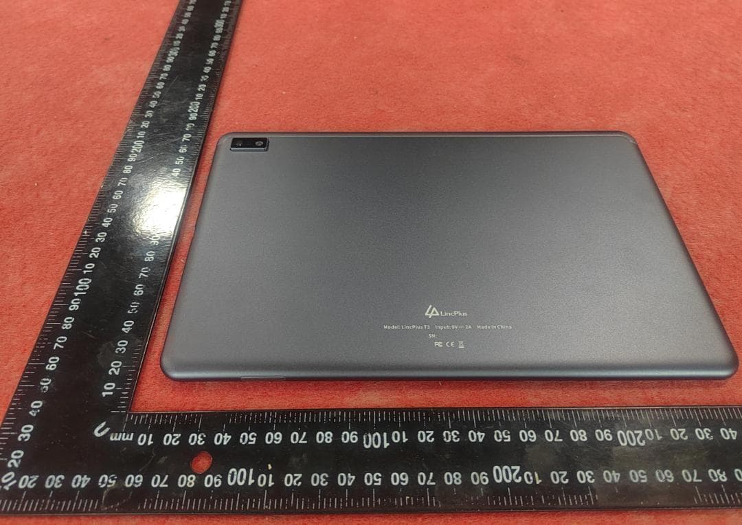
2AHYJ-TVE1070M
May 22, 2023Tablet
Equipment Class
JBC - Part 15 Class B Computing Device/Personal Computer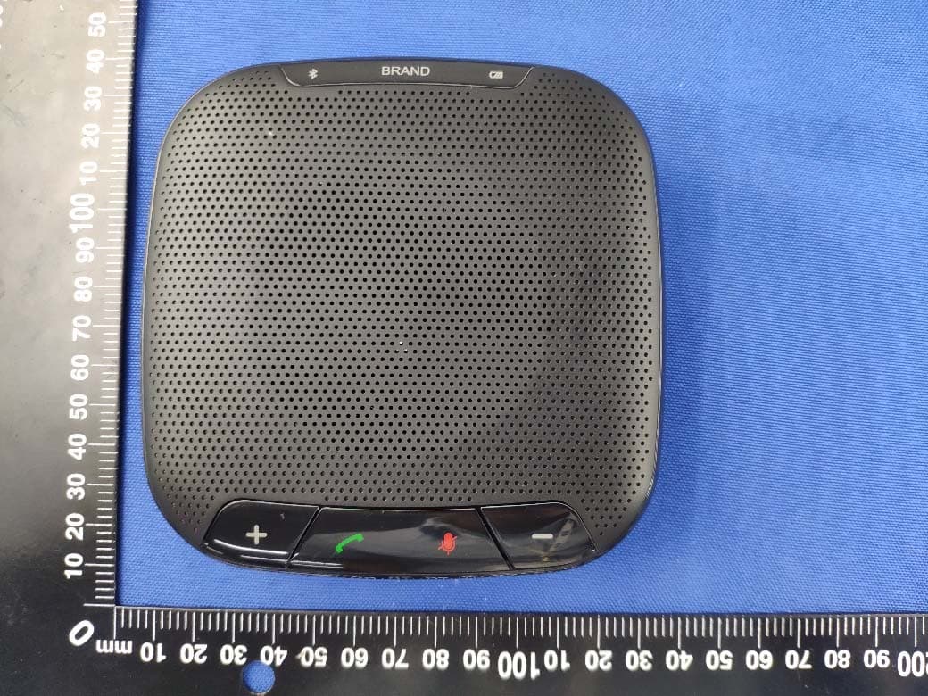
2AHYJTVD5010
May 31, 2021Omnidirectional microphone with Bluetooth
Equipment Class
DSS - Part 15 Spread Spectrum Transmitter
2AHYJ-TVE1409P
Feb 08, 2021Notebook
Equipment Class
DTS - Digital Transmission System