2AHZ5NOTE7Smart Phone
Shenzhen Huafurui Technology Co., Ltd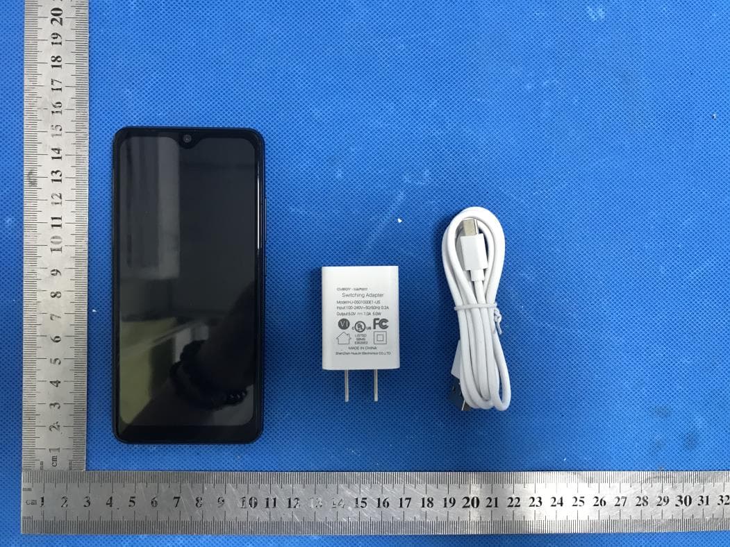
Click to zoom
Application Details
- Equipment Class
- DTS - Digital Transmission System
- Date of Grant
- Sep 15, 2020
- Application Purpose
- Original Equipment
- Date of Application
- Sep 15, 2020
- Equipment Note
- Smart Phone
- Frequency Range
- 2412.00000000 - 2462.00000000
- Country
- China
Documents & Files
Document Text
Text extracted from the exhibit documents filed with the FCC. Open a document above to read the original.
Users Manual
1 CUBOT User Manual Smartphone CUBOT NOTE 7 Shenzhen Huafurui Technology Co., Ltd. 2 Table of Contents Safety Information ............................................................. 4 Introduction ......................................................................... 6 Call Functions ..................................................................... 7 Contacts ............................................................................... 9 Message ............................................................................. 12 FM Radio ............................................................................ 17 Camera ................................................................................ 23 3 Gallery ................................................................................. 25 Music ................................................................................... 27 Sound Recorder ............................................................... 27 Alarm Clock ....................................................................... 29 Play Store ........................................................................... 30 Settings .............................................................................. 32 Storage ............................................................................... 38 FCC Rules Compliance ................................................... 40 IC Notice ............................................................................. 44 4 Safety Information Please carefully read the iterms bellow: Use Safely Do not use the phone in situations where it might cause danger. Transportation Safety Please observe all transportation laws and regulations. Please drive with both hands on the wheel. Hospitals Please follow limitations. 5 Please turn off your mobile phone when near medical instruments. Airports Remember to follow all airport and flight safety regulations. Please do not use your phone during flight. Toxic Chemicals Do not use your mobile phone around fuels or chemicals. Hazard Do not use in hazardous areas where explosions may occur. Accessories and Batteries Use only Blu authorized batteries and accessories. Backup Remember to keep a written record of all important information. Water Your phone is not waterproof. Keep it away from water and liquids. 6 SOS Emergency Calls Make sure your mobile phone is switched on and in a service area. In home screen, tap the phone key and dial 911 and send. Introduction Power On and Off On - Please ensure the SIM card has been properly inserted into the phone. Long press the Power key to switch on the phone. Off - In standby mode, long press on Power key until an options menu appears. Select 7 Power Off in the menu and confirm Security You may set a security lock feature as a security measure for the phone. For further information regarding password locks, password revision and other functions please enter into the security option in system settings. Call Functions At the dial keyboard, enter the phone number and then click the dial key. If dialing an extension, you may click the dial pad icon in the bottom of the screen to open the interface and enter the number of the extension. You may also press and hold the 0 key to add a (+) sign when adding an international dialing prefix. history 8 Every telephone number called and received will be saved in the history. All numbers in the history can be dialed directly by clicking the CALL BACK on the screen. When the number appears on the list, click it to view details. Call Options 9 There are different options that can be used in the history and dialing interface. You may press the MORE while in the dial interface and adjust speed dial and call settings. In the dialing interface, you may press the search button to browse through contacts list or set default contact resources. Contacts 10 Enter: Click on the applications menu and select contacts. • The default display is the phone contacts and SIM card contacts. • The contacts are organized alphabetically by default. Add Contact 11 Click the Search icon to enter the contact search interface. Any numbers or letters associated with any of the contacts saved in the list will be shown in the search results. Add New Contact 1. Click the add contact icon (+) to add contact. 2. Select to save your contacts to the Google TM account, the phone or the SIM card. 3. You may enter different contact details which include adding a picture, name, telephone number, group, address, and email among other options. 4. Click to finish and save contact. 12 Messages You may use this function to exchange text messages and multimedia messages with your 13 family and friends. The messages to and from the same contact or phone number will be saved into a single conversation so you may see the entire message history conveniently. Send an SMS Application Menu » Messaging » New message (or shortcut icon) 14 1. Click to enter recipient (You may enter contacts from contact book or enter a new number) 2. Compose Message 3. Send Send an MMS When creating message, the default message style is SMS. The message will automatically convert to MMS when adding an attachment. 1. Click the attachment icon in the messaging interface. 2. Click to add attachments and create an MMS message. Internet Browser Menu Functions •Recent tab • After browsing through multiple pages, this option will return the user to the previous page. Windows • You may view all windows open by clicking the windows icon in the upper right part of the browser. 15 Bookmarks • Click the save to Bookmarks option to make the current URL as a saved Bookmark. • Click Bookmarks/History to opened saved bookmarks. Find on page: Search current page. Share page: Select to share the current page. Bookmarks/History: Show your browsing history and view the most visited pages. Settings: Contains a variety of browser settings. 16 17 FM Radio FM Radio Through this program, you may li…
Text truncated - open the document above for the full version.
External Photos
External Photos All VIEW OF EUT TOP VIEW OF EUT BOTTOM VIEW OF EUT FRONT VIEW OF EUT BACK VIEW OF EUT LEFT VIEW OF EUT RIGHT VIEW OF EUT
ID Label/Location Info
FCC ID Label Location FCC ID:2AHZ5NOTE7
Internal Photos
Internal Photos OPEN VIEW OF EUT(FIGURE 1) OPEN VIEW OF EUT(FIGURE 2) BT/WIFI/GPS Antenna Diversity Antenna GSM/WCDMA/LTE Antenna OPEN VIEW OF EUT(FIGURE 3) OPEN VIEW OF EUT(FIGURE 4) WIFI&BT&GPS ANTENNA GSM& WCDMA& LTE ANTENNA DIVERSITY ANTENNA INTERNAL VIEW OF EUT(FIGURE 1) INTERNAL VIEW OF EUT(FIGURE 2) INTERNAL VIEW OF EUT(FIGURE 2) INTERNAL VIEW OF EUT(FIGURE 3) INTERNAL VIEW OF EUT(FIGURE 4) INTERNAL VIEW OF EUT(FIGURE 5) INTERNAL VIEW OF EUT(FIGURE 6) INTERNAL VIEW OF EUT(FIGURE 7) INTERNAL VIEW OF EUT(FIGURE 8) INTERNAL VIEW OF EUT(FIGURE 9)
Operational Description
Shenzhen Huafurui Technology Co., Ltd. Declaration concerning Antenna Specification It is hereby declared that the product Model No.: NOTE 7 FCC ID: 2AHZ5NOTE7 fulfills the requirement in FCC test relating to the antenna type. The device specified above confirms to the FCC recommendations for internal antenna type(s) described below: 1. Type of antenna: PIFA Antenna Gain of the antenna: 1.73 dBi Frequency range: 2402-2480 MHz 2. Type of antenna: PIFA Antenna Gain of the antenna: 1.74 dBi Frequency range: 2412-2462 MHz 3. Type of antenna: PIFA Antenna Gain of the antenna: 0.86dBi Frequency range: 824.2-848.8 MHz Gain of the antenna: 1.35dBi Frequency range: 1850.2-1909.8 MHz Gain of the antenna: 1.34dBi II Frequency range: 1852.4-1907.6 MHz Gain of the antenna: 0.87 dBi V Frequency range: 826.4-846.6 MHz Gain of the antenna: 1.27 dBi IV Frequency range: 1712.4-1752.6MHz Shenzhen Huafurui Technology Co., Ltd. 4. Type of antenna: PIFA Antenna Gain of the antenna: 1.38 dBi Frequency range: 1850-1909.9 MHz Gain of the antenna: 1.28 dBi Frequency range: 1710-1754.9MHz Gain of the antenna: 1.21dBi Frequency range: 2500-2569.9MHz Gain of the antenna: 0.84 dBi Frequency range: 824-848.9 MHz Gain of the antenna: 0.32 dBi Frequency range: 699-715.9 MHz Gain of the antenna: 0.38dBi Frequency range: 704 - 715.9 MHz The mounting of the antenna is fixed to the radio module and no other antenna should be used. Company name: Shenzhen Huafurui Technology Co., Ltd. Address: Unit 1401 14/F, Jin qi zhi gu mansion Liu xian street ,Xili, Nan shan district Shenzhen,China Place: Shenzhen Date: 2020-09-14 Signature:
RF Exposure Info
Page 1 of 145 SAR Test Report Report No.: AGC00552200701FH01 FCC ID : 2AHZ5NOTE7 APPLICATION PURPOSE : Original Equipment PRODUCT DESIGNATION : Smart Phone BRAND NAME : CUBOT MODEL NAME : NOTE 7 APPLICANT : Shenzhen Huafurui Technology Co., Ltd. DATE OF ISSUE : Sep. 11.2020 STANDARD(S) : IEEE Std. 1528:2013 FCC 47 CFR Part 2§2.1093:2013 IEEE Std C95.1 ™-2005 IEC 62209-1: 2016 REPORT VERSION : V1.0 Attestation of Global Compliance(Shenzhen) Co., Ltd. Report No.: AGC00552200701FH01 Page 2 of 145 Report Revise Record Report Version Revise Time Issued Date Valid Version Notes V1.0 / Sep. 11.2020 Valid Initial Release Report No.: AGC00552200701FH01 Page 3 of 145 Test Report Applicant Name Shenzhen Huafurui Technology Co., Ltd. Applicant Address Unit 1401 14/F, Jin qi zhi gu mansion Liu xian street, Xili, Nan shan district, Shenzhen, China Manufacturer Name Shenzhen Huafurui Technology Co., Ltd. Manufacturer Address Unit 1401 14/F, Jin qi zhi gu mansion Liu xian street, Xili, Nan shan district, Shenzhen, China Factory Name Shenzhen Huafurui Technology Co., Ltd. Factory Address Unit 1401 14/F, Jin qi zhi gu mansion Liu xian street, Xili, Nan shan district, Shenzhen, China Product Designation Smart Phone Brand Name CUBOT Model Name NOTE 7 EUT Voltage DC3.8V by battery Applicable Standard IEEE Std. 1528:2013 FCC 47 CFR Part 2§2.1093:2013 IEEE Std C95.1 ™-2005 IEC 62209-1: 2016 Test Date Aug. 01.2020 to Aug. 10.2020 Report Template AGCRT-US-4G/SAR (2018-01-01) Note: The results of testing in this report apply to the product/system which was tested only. Prepared By Jack Gui (Project Engineer) Aug. 10.2020 Reviewed By Angela Li (Reviewer) Sep. 11.2020 Approved By Forrest Lei (Authorized Officer) Sep. 11.2020 Report No.: AGC00552200701FH01 Page 4 of 145 TABLE OF CONTENTS 1. SUMMARY OF MAXIMUM SAR VALUE ....................................................................................................... 5 2. GENERAL INFORMATION ............................................................................................................................ 6 2.1. EUT DESCRIPTION ...................................................................................................................................... 6 3. SAR MEASUREMENT SYSTEM ..................................................................................................................... 8 3.1. THE DASY5 SYSTEM USED FOR PERFORMING COMPLIANCE TESTS CONSISTS OF FOLLOWING ITEMS.................... 8 3.2. DASY5 E-FIELD PROBE .............................................................................................................................. 9 3.3. DATA ACQUISITION ELECTRONICS DESCRIPTION ............................................................................................. 9 3.4. ROBOT ..................................................................................................................................................... 10 3.5. LIGHT BEAM UNIT ..................................................................................................................................... 10 3.6. DEVICE HOLDER ........................................................................................................................................ 11 3.7. MEASUREMENT SERVER ............................................................................................................................. 11 3.8. PHANTOM .............................................................................................................................................. 12 4. SAR MEASUREMENT PROCEDURE ........................................................................................................... 13 4.1. SPECIFIC ABSORPTION RATE (SAR) ........................................................................................................... 13 4.2. SAR MEASUREMENT PROCEDURE ............................................................................................................. 14 4.3. RF EXPOSURE CONDITIONS ....................................................................................................................... 16 5. TISSUE SIMULATING LIQUID ...................................................................................................................... 18 5.1. THE COMPOSITION OF THE TISSUE SIMULATING LIQUID ................................................................................... 18 5.2. TISSUE DIELECTRIC PARAMETERS FOR HEAD AND BODY PHANTOMS .............................................................. 19 5.3. TISSUE CALIBRATION RESULT ..................................................................................................................... 20 6. SAR SYSTEM CHECK PROCEDURE ......................................................................................................... 22 6.1. SAR SYSTEM CHECK PROCEDURES ........................................................................................................... 22 6.2. SAR SYSTEM CHECK ................................................................................................................................ 23 7. EUT TEST POSITION ................................................................................................................................... 25 7.2. CHEEK POSITION ...................................................................................................................................... 26 7.3. TILT POSITION ........................................................................................................................................... 26 7.4. BODY WORN POSITION .............................................................................................................................. 27 8. SAR EXPOSURE LIMITS ............................................................................................................................ 28 9. TEST FACILITY ..................................…
Text truncated - open the document above for the full version.
Test Report
Page 1 of 42 FCC Test Report Report No.: AGC00552200701FE08 FCC ID : 2AHZ5NOTE7 APPLICATION PURPOSE : Original Equipment PRODUCT DESIGNATION : Smart Phone BRAND NAME : CUBOT MODEL NAME : NOTE 7 APPLICANT : Shenzhen Huafurui Technology Co., Ltd. DATE OF ISSUE : Sep. 09, 2020 STANDARD(S) : FCC Part 15.247 REPORT VERSION : V1.0 Attestation of Global Compliance (Shenzhen) Co., Ltd Report No.: AGC00552200701FE08 Page 2 of 42 REPORT REVISE RECORD Report Version Revise Time Issued Date Valid Version Notes V1.0 / Sep. 09, 2020 Valid Initial Release Report No.: AGC00552200701FE08 Page 3 of 42 TABLE OF CONTENTS 1. VERIFICATION OF COMPLIANCE ......................................................................................... 5 2. GENERAL INFORMATION ...................................................................................................... 6 2.1. PRODUCT DESCRIPTION ...................................................................................................................... 6 2.2. TABLE OF CARRIER FREQUENCYS .................................................................................................... 6 2.3. RELATED SUBMITTAL(S)/GRANT(S) .................................................................................................... 7 2.4. TEST METHODOLOGY .......................................................................................................................... 7 2.5. SPECIAL ACCESSORIES ....................................................................................................................... 7 2.6. EQUIPMENT MODIFICATIONS .............................................................................................................. 7 2.7. ANTENNA REQUIREMENT .................................................................................................................... 7 3. MEASUREMENT UNCERTAINTY ........................................................................................... 8 4. DESCRIPTION OF TEST MODES ........................................................................................... 9 5. SYSTEM TEST CONFIGURATION ........................................................................................ 10 5.1. CONFIGURATION OF TESTED SYSTEM ............................................................................................ 10 5.2. EQUIPMENT USED IN TESTED SYSTEM ........................................................................................... 10 5.3. SUMMARY OF TEST RESULTS ........................................................................................................... 10 6. TEST FACILITY ...................................................................................................................... 11 7. PEAK OUTPUT POWER ....................................................................................................... 12 7.1. MEASUREMENT PROCEDURE ........................................................................................................... 12 7.2. TEST SET-UP (BLOCK DIAGRAM OF CONFIGURATION) ................................................................. 12 7.3. LIMITS AND MEASUREMENT RESULT ............................................................................................... 13 8. 6 DB BANDWIDTH ................................................................................................................ 15 8.1. MEASUREMENT PROCEDURE ........................................................................................................... 15 8.2. TEST SET-UP (BLOCK DIAGRAM OF CONFIGURATION) ................................................................. 15 8.3. LIMITS AND MEASUREMENT RESULTS ............................................................................................ 15 9. CONDUCTED SPURIOUS EMISSION .................................................................................. 17 9.1. MEASUREMENT PROCEDURE ........................................................................................................... 17 9.2. TEST SET-UP (BLOCK DIAGRAM OF CONFIGURATION) ................................................................. 17 9.3. MEASUREMENT EQUIPMENT USED .................................................................................................. 17 9.4. LIMITS AND MEASUREMENT RESULT ............................................................................................... 17 10. MAXIMUM CONDUCTED OUTPUT POWER SPECTRAL DENSITY ................................. 22 10.1. MEASUREMENT PROCEDURE ......................................................................................................... 22 10.2. TEST SET-UP (BLOCK DIAGRAM OF CONFIGURATION) ............................................................... 22 10.3. MEASUREMENT EQUIPMENT USED ................................................................................................ 22 Report No.: AGC00552200701FE08 Page 4 of 42 10.4. LIMITS AND MEASUREMENT RESULT ............................................................................................. 22 11. RADIATED EMISSION ......................................................................................................... 24 11.1. MEASUREMENT PROCEDURE ......................................................................................................... 24 11.2. TEST SETUP ....................................................................................................................................... 25 11.3. LIMITS AND MEASUREMENT RESULT ............................................................................................. 26 11.4. TEST RESULT .................................................................................................................................... 26 12. FCC LINE CONDUCTED EMISSION TEST ........................................................................ 36 12.1. LIMITS OF LINE CONDUCTED EMISSION TEST ..........................…
Text truncated - open the document above for the full version.
Test Setup Photos
Test Setup Photos RADIATED EMISSION TEST SETUP BELOW 1GHz RADIATED EMISSION TEST SETUP ABOVE 1GHz CONDUCTED EMISSION TEST SETUP CONDUCTED TEST SETUP
Contact Information
Applicant
Paul Liu
Test Firm
Attestation of Global Compliance (Shenzhen) Co., LDoris Li
[email protected]+86-755-25234088
Technical Specifications
| # | Rule Parts | Frequency Range | Power Output |
|---|---|---|---|
| 2 | 15C | 2.41 GHz - 2.46 GHz | 10.20 mW |
Other Applications from Shenzhen Huafurui Technology Co., Ltd
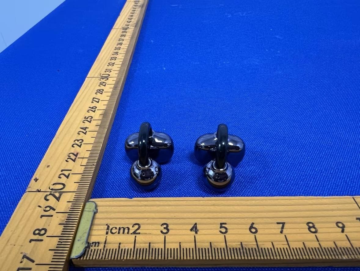
2AHZ5-NEO-A
Jun 11, 2026Wireless Earphone
Equipment Class
DSS - Part 15 Spread Spectrum Transmitter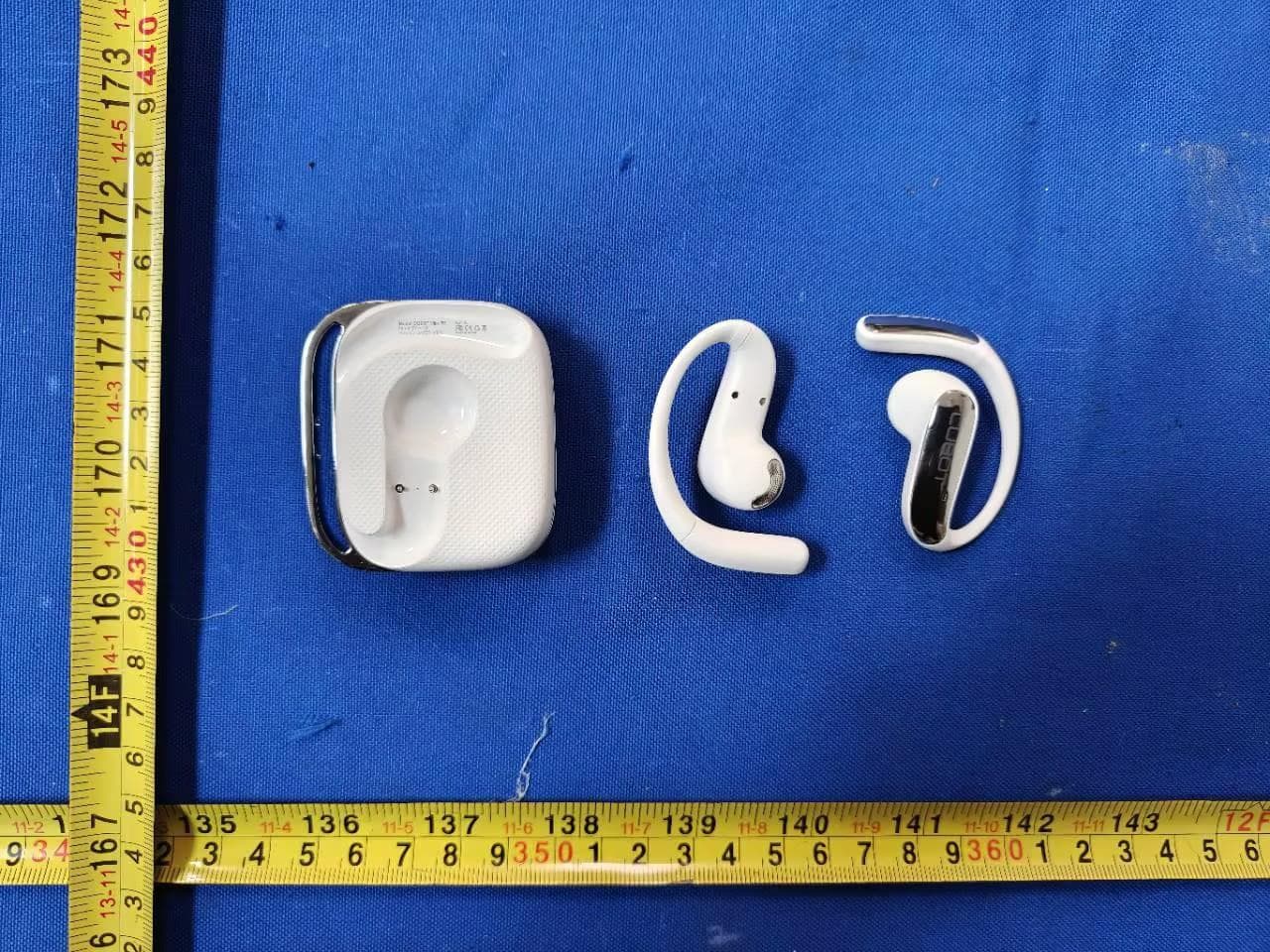
2AHZ5-VR5
Jun 11, 2026Wireless Earphone
Equipment Class
DTS - Digital Transmission System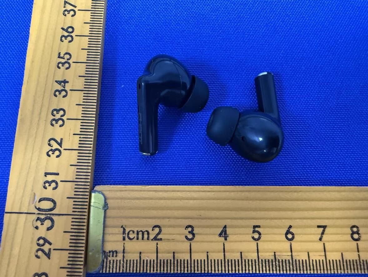
2AHZ5-BUDS
Jun 11, 2026Wireless Earphone
Equipment Class
DSS - Part 15 Spread Spectrum Transmitter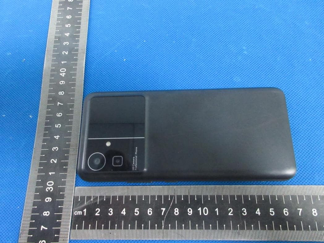
2AHZ5N21
Jul 19, 2023Smartphone
Equipment Class
NII - Unlicensed National Information Infrastructure TX
2AHZ5N50
Jun 25, 2023Smartphone
Equipment Class
DSS - Part 15 Spread Spectrum Transmitter