2AHZ5SW10Projector
Shenzhen Huafurui Technology Co., Ltd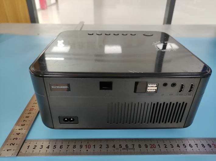
Click to zoom
Application Details
- Equipment Class
- DSS - Part 15 Spread Spectrum Transmitter
- Date of Grant
- Nov 23, 2021
- Application Purpose
- Original Equipment
- Date of Application
- Nov 23, 2021
- Equipment Note
- Projector
- Frequency Range
- 2402.00000000 - 2480.00000000
- Country
- China
Documents & Files
Document Text
Text extracted from the exhibit documents filed with the FCC. Open a document above to read the original.
Users Manual
Projector User Manual Please read this user manual carefully before start using the projector 1.Important Safety Matters 2.Know Your Projector 3. Function for Rem ote Control Buttons 4. Installation of Projector: A: Standard Setting b. Installation Methods 5.Switch On&Off Operation 6. Image Correction 7. Interface operation instructions: 1. How to choose signal source. 2. How to connect to wifi. 3. How to play U-disk. 4. How to set electric keystone correction. 5. How to use Bluetooth. 6. How to use Android scr een projection. 7. How to use iOS scr een projection. 8. System upgrade. 8.Multimedia play formats 9.Simple troubleshooting Important Safety Matters Installation To achieve the best effect, please use the projector in a darker room or draw the curtains. Be careful when use the projector. Any dropping or bump may lead to damaged parts, blurred images or display improperly. Power Source Be careful to the power cord to avoid excessive bending. Damaged power cord may cause electric shock and fire. Please unplug the power cord from the socket after use. Cleaning Unplug the power first. Clean the cabinet regularly with a damp cloth. Neutral detergent can be used. Do not use strong detergents or solvents (such as alcohol and thinner). The lens should be cleaned with glasses cloth or lens paper. Be careful not to scr atch the lens. Use a soft brush to clean the vents and speaker of the projector regularly, or the vents will be blocked by dust and cause the machine breakdown due to overheat. High Temperature Attention Do not disassemble the projector casually since there may be a risk of electric shock, which affects normal maintenance. Liquid or heavy objects should not allowed on the machine. Know Your Projector Projector Accessories Description The projector can input HDMI high-definition video signals, and supports stereo audio signal input and output. Connect the projector and other equipment according to the following picture. 1.Adjustable tripod. 2. Remote control signal receiver. 3. Projector lens. 4. Power socket. 5. Rem ote control signal receiver. 6. Audio output connector. 7. HDMI 1 HD connector. 8. USB connector, 9. AV connector. 10. HDMI 2 HD connector. 11. Horn. 12. Heat dissipation window. 13. Focusing dial. 14. Detachable dust-proof net switch, move right to disassemble the dust-proof net. 15. Removable dust-proof net. 1.Press the button (Figure 1). 2. Bottom sticker. 3. Hanger fixing hole, can be used after removing the foot pad. 4. Height adjustment machine feet. 1.Power button 2.Back button 3.Confirm button 4.Up button 5.Down button 6.Left button 7.Right button Function for Remote Control Buttons Projector Accessories Description 1. Indicator light. 2. Power button. 3. Signal source button. 4. Direction button. 5. Menu button. 6. Home button. 7. Volume +. 8. Volume -. 9. Mute button. 10. Screen switch Button. 11. Confirm button. 12. Back button. 13. Last song. 14. Next song. Standard Setting Refer to the data below and place the projector at the appropriate distance from the screen according to required size of the screen . Please place the projector on a smooth and solid table top, or suspend it from the ceiling. The area around the projector should be well ventilated to avoid blocking the vents. There should be no other objects within 30cm around the vents. Note: The above data is for ref erenc e only, please ref er to the actual measurement data. These figures may vary due to differences in optics. Suggestion: Please physically adapt the distance and screen size before installation. Attention To avoid distortion of the projected image after projection, place the projection as close to the axis of symmetry as possible. Installation methods Depending on the environment and requirements, this projector can be suspended from the ceiling using a professional projection stand, or placed on a smooth tabletop. Or choose another mounting option according to the following illustrations. Attention Matters 1. When using the hanging method, the projector should not be higher than the top edge of the screen, or it will affect the screen imaging effect and keystone correction. 2. The projector should be installed on the left and right axis of symmetry of the screen to avoid left and right keystone distortion of the image. 3. The space around the projector should be well ventilated after installation and there should not be any objects blocking the way of the vents. 4. Please do not connect the power source during installation to avoid electric shock or projector circuit failure. 5. Projector just installed may be blurred and trapezoidal distorted, please refer to the section on graphic calibration for correction. Projector On/Off Switch on/off operation Connect the projector to the power supply, the projector enters standby mode and the power light is red. Power on: Press the power button on the projector, or the power button on the rem ote control, the power indicator turns to blue from red and enters the working status. Power off: In the working state, press the power button on projector or remote control, the power indicator changes to red from blue and the projector is turned off. Image correction Dial clockwise to the end (below), then dial counterclockwise while watching the particle spots on the image, stopping at the sharpest point, which is the best position for focusing. Dial W heel Instructions for Interface operation 1. How to choose the signal source After entering the main interface, press the signal source button " " on the power button, select the required signal source channel in the pop-up interface, such as "HDMI1, HDMI2, AV", etc., and press the OK button on the remote control to enter the corresponding signal source status. 2. How to connect wife Enter the main interface, Sys tem Settings, Network Settings - WiFi Settings; find the network you want to connect to and press Confirm. Enter the password via the virtual keyboard and confirm the connection. Password:…
Text truncated - open the document above for the full version.
Attestation Statements
Shenzhen Huafurui Technology Co., Ltd Address: Unit 1401 14/F, Jin qi zhi gu mansion Liu xian street ,Xili, Nan shan district Shenzhen China Email: [email protected] Tel: 0755-82750456 Fax: 0755-82750456 Date: 2021-11 -03 FEDERAL COMMUNICATIONS COMMISSIONS Authorization and Evaluation Division 7435 Oakland Mills Road Columbia, MD 21046 Dear Sir/Madam, (Product Name: Projector; Model: SW10; FCC ID:2AHZ5SW10) The chipset RTL8822CU used in this device for US only supports Bluetooth BDR(GFSK), EDR(π/4-DQPSK, 8DPSK), 2.4G WIFI(2412-2462MHz), 5G WIFI BAND1(5150-5250MHz), other functions were disabled by software. Signature: Printed Name: Paul Liu Title: Project Manager
Cover Letter(s)
Shenzhen Huafurui Technology Co., Ltd Address: Unit 1401 14/F, Jin qi zhi gu mansion Liu xian street ,Xili, Nan shan district Sh enzhen China Email: [email protected] Tel: 0755-82750456 Fax: 0755-82750456 FCC Confidential Authorization Date: 2021-10 -28 FEDERAL COMMUNICATIONS COMMISSIONS Authorization and Evaluation Division 7435 Oakland Mills Road Columbia, MD 21046 Subject: Confidentiality Request regarding application for certification of FCC ID: 2AHZ5SW10 In accordance with Sections 0.457 and 0.459 of the Commission’s Shenzhen Huafurui Technology Co., Ltd hereby requests long-term confidential treatment of information accompanying this application as outlined below: Block Diagram Schematics Operation Description SOFTWARE SECURITY DESCRIPTION The above materials contain proprietary and confidential information not customarily released to the public. The public disclosure of these materials provides unjustified benefits to its competitors in the market. Sincerely Yours, Signature: Printed Name: Paul Liu Title: Project Manager
External Photos
Shenzhen Accurate Technology Co., Ltd. Project No.: SZ1210918-48944E-RF External Photos Page 1 of 3 External Photos Shenzhen Accurate Technology Co., Ltd. Project No.: SZ1210918-48944E-RF External Photos Page 2 of 3 Shenzhen Accurate Technology Co., Ltd. Project No.: SZ1210918-48944E-RF External Photos Page 3 of 3
Internal Photos
Shenzhen Accurate Technology Co., Ltd. Project No.: SZ1210918-48944E-RF Internal Photos Page 1 of 9 Internal photos Antenna 1 BT/2.4G Wi-Fi / 5G Wi-Fi Antenna 0 2.4G Wi-Fi / 5G Wi-Fi Shenzhen Accurate Technology Co., Ltd. Project No.: SZ1210918-48944E-RF Internal Photos Page 2 of 9 Shenzhen Accurate Technology Co., Ltd. Project No.: SZ1210918-48944E-RF Internal Photos Page 3 of 9 Shenzhen Accurate Technology Co., Ltd. Project No.: SZ1210918-48944E-RF Internal Photos Page 4 of 9 Shenzhen Accurate Technology Co., Ltd. Project No.: SZ1210918-48944E-RF Internal Photos Page 5 of 9 Shenzhen Accurate Technology Co., Ltd. Project No.: SZ1210918-48944E-RF Internal Photos Page 6 of 9 Shenzhen Accurate Technology Co., Ltd. Project No.: SZ1210918-48944E-RF Internal Photos Page 7 of 9 Shenzhen Accurate Technology Co., Ltd. Project No.: SZ1210918-48944E-RF Internal Photos Page 8 of 9 Shenzhen Accurate Technology Co., Ltd. Project No.: SZ1210918-48944E-RF Internal Photos Page 9 of 9
RF Exposure Info
Shenzhen Accurate Technology Co., Ltd. Report No.: SZ1210918-48944E-00A FCC Part 15.247 Page 11 of 63 FCC §1.1310 & §2.1091 –MAXIMUM PERMISSIBLE EXPOSURE (MPE) Applicable Standard According to subpart §2.1091 and subpart §1.1310, systems operating under the provisions of this section shall be operated in a manner that ensures that the public is not exposed to radio frequency energy level in excess of the Commission’s guidelines. Limits for Maximum Permissible Exposure (MPE) (§1.1310, §2.1091) (B) Limits for General Population/Uncontrolled Exposure Frequency Range (MHz) Electric Field Strength (V/m) Magnetic Field Strength (A/m) Power Density (mW/cm 2 ) Averaging Time (minutes) 0.3-1.34 614 1.63 *(100) 30 1.34-30 824/f 2.19/f *(180/f²) 30 30-300 27.5 0.073 0.2 30 300-1500 / / f/1500 30 1500-100,000 / / 1.0 30 f = frequency in MHz; * = Plane-wave equivalent power density; According to §1.1310 and §2.1091 RF exposure is calculated. Calculated Formulary: Predication of MPE limit at a given distance S = PG/4πR² = power density (in appropriate units, e.g. mW/cm 2 ); P = power input to the antenna (in appropriate units, e.g., mW); G = power gain of the antenna in the direction of interest relative to an isotropic radiator, the power gain factor, is normally numeric gain; R = distance to the center of radiation of the antenna (appropriate units, e.g., cm); Calculated Data: For worst case: Mode Frequency Range (MHz) Antenna Gain Tune-up Output Power Evaluation Distance (cm) Power Density (mW/cm 2 ) MPE Limit (mW/cm 2 ) (dBi) (numeric) (dBm) (mW) BT 2402-2480 -0.76 0.84 9.0 7.94 20 0.0013 1.0 To maintain compliance with the FCC’s RF exposure guidelines, place the equipment at least 20cm from nearby persons. Result: Compliant.
Test Report
Note: This report may contain data that are not covered by the A2LA accreditation and are marked with an asterisk “★”. Shenzhen Accurate Technology Co., Ltd. is not responsible for the authenticity of any test data provided by the applicant. Data included from the applicant that may affect test results are marked with an asterisk ’*’. Customer model name, addresses, names, trademarks etc. are not considered data. This report cannot be reproduced except in full, without prior written approval of the Company. Unless otherwise stated the results shown in this test report refer only to the sample(s) tested. This report is valid only with a valid digital signature. The digital signature may be available only under the Adobe software above version 7.0. FCC PART 15.247 TEST REPORT For Shenzhen Huafurui Technology Co., Ltd Unit 1401 14/F, Jin qi zhi gu mansion Liu xian street, Xili, Nan shan district, Shenzhen, China FCC ID: 2AHZ5SW10 Report Type: Original Report Product Type: Projector Report Number: SZ1210918-48944E-00A Report Date: 2021-11-02 Reviewed By: Candy Li RF Engineer Prepared By: Shenzhen Accurate Technology Co., Ltd. 1/F., Building A, Changyuan New Material Port, Science & Industry Park, Nanshan District, Shenzhen, Guangdong, P.R. China Tel: (0755) 26503290 Fax: (0755) 26503396 Http://www.atc-lab.com Shenzhen Accurate Technology Co., Ltd. Report No.: SZ1210918-48944E-00A FCC Part 15.247 Page 2 of 63 TABLE OF CONTENTS GENERAL INFORMATION ....................................................................................................................................... 4 PRODUCT DESCRIPTION FOR EQUIPMENT UNDER TEST (EUT) ..................................................................................... 4 OBJECTIVE ................................................................................................................................................................... 4 TEST METHODOLOGY .................................................................................................................................................. 4 MEASUREMENT UNCERTAINTY .................................................................................................................................... 5 TEST FACILITY ............................................................................................................................................................. 5 SYSTEM TEST CONFIGURATION .......................................................................................................................... 6 DESCRIPTION OF TEST CONFIGURATION ...................................................................................................................... 6 EUT EXERCISE SOFTWARE .......................................................................................................................................... 6 SPECIAL ACCESSORIES ................................................................................................................................................. 6 EQUIPMENT MODIFICATIONS ....................................................................................................................................... 6 SUPPORT EQUIPMENT LIST AND DETAILS .................................................................................................................... 6 EXTERNAL I/O CABLE.................................................................................................................................................. 6 BLOCK DIAGRAM OF TEST SETUP ................................................................................................................................ 7 SUMMARY OF TEST RESULTS ............................................................................................................................... 9 TEST EQUIPMENT LIST ......................................................................................................................................... 10 FCC §1.1310 & §2.1091 –MAXIMUM PERMISSIBLE EXPOSURE (MPE) ....................................................... 11 FCC §15.203 – ANTENNA REQUIREMENT .......................................................................................................... 12 APPLICABLE STANDARD ............................................................................................................................................ 12 ANTENNA CONNECTOR CONSTRUCTION .................................................................................................................... 12 FCC §15.207 (a) – AC LINE CONDUCTED EMISSIONS ..................................................................................... 13 APPLICABLE STANDARD ............................................................................................................................................ 13 EUT SETUP ................................................................................................................................................................ 13 EMI TEST RECEIVER SETUP ....................................................................................................................................... 13 TEST PROCEDURE ...................................................................................................................................................... 13 TRANSD FACTOR & MARGIN CALCULATION ............................................................................................................. 14 TEST DATA ................................................................................................................................................................ 14 FCC §15.205, §15.209 & §15.247(d) – RADIATED EMISSIONS ........................................................................... 17 APPLICABLE STANDARD ...................................................................................................................................…
Text truncated - open the document above for the full version.
Test Setup Photos
Shenzhen Accurate Technology Co., Ltd. Project No.: SZ1210918-48944E-RF Test Photos Page 1 of 4 Photo of Conducted Emission Measurement Shenzhen Accurate Technology Co., Ltd. Project No.: SZ1210918-48944E-RF Test Photos Page 2 of 4 Photo of Radiated Emission Measurement (Below 1G) Shenzhen Accurate Technology Co., Ltd. Project No.: SZ1210918-48944E-RF Test Photos Page 3 of 4 Photo of Radiated Emission Measurement (Above 1G) Shenzhen Accurate Technology Co., Ltd. Project No.: SZ1210918-48944E-RF Test Photos Page 4 of 4
Contact Information
Applicant
Paul Liu
Test Firm
Shenzhen Accurate Technology Co., Ltd.Lisa Zhang
[email protected]+86-755-26503290
Technical Specifications
| # | Rule Parts | Frequency Range | Power Output |
|---|---|---|---|
| 1 | 15C | 2.40 GHz - 2.48 GHz | 8.00 mW |
Other Applications from Shenzhen Huafurui Technology Co., Ltd
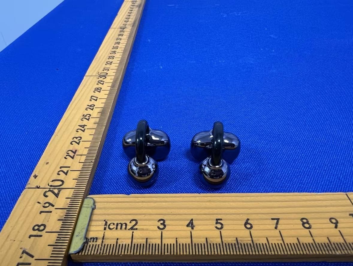
2AHZ5-NEO-A
Jun 11, 2026Wireless Earphone
Equipment Class
DSS - Part 15 Spread Spectrum Transmitter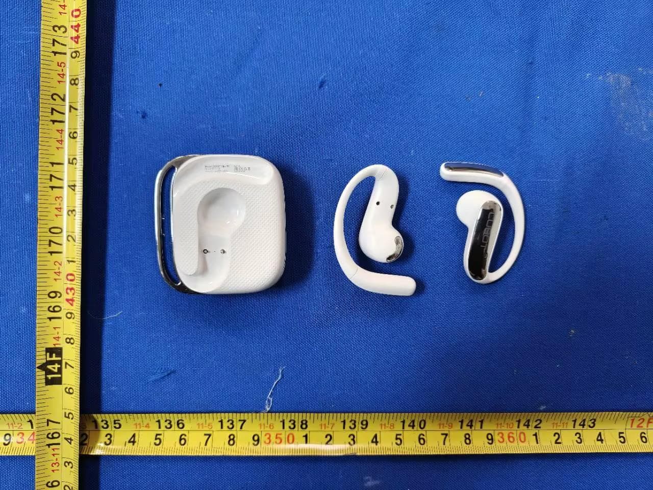
2AHZ5-VR5
Jun 11, 2026Wireless Earphone
Equipment Class
DTS - Digital Transmission System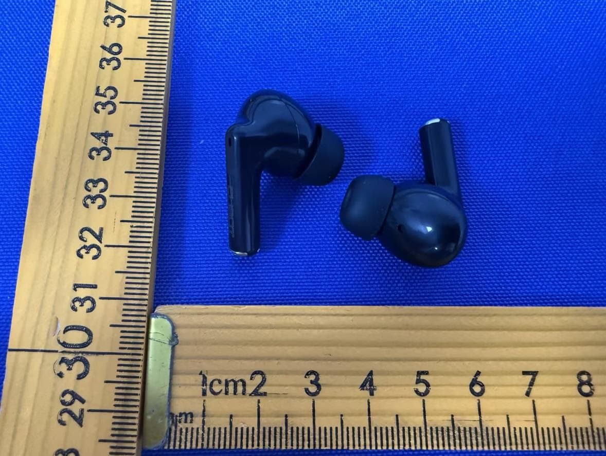
2AHZ5-BUDS
Jun 11, 2026Wireless Earphone
Equipment Class
DSS - Part 15 Spread Spectrum Transmitter
2AHZ5N21
Jul 19, 2023Smartphone
Equipment Class
NII - Unlicensed National Information Infrastructure TX
2AHZ5N50
Jun 25, 2023Smartphone
Equipment Class
DSS - Part 15 Spread Spectrum Transmitter