2AI5QGA-RT0001Receiver/Transponder
Taiwan Aulisa Medical Devices Technologies, Inc.
Click to zoom
Application Details
- Equipment Class
- DTS - Digital Transmission System
- Date of Grant
- Feb 01, 2020
- Application Purpose
- Original Equipment
- Date of Application
- Feb 01, 2020
- Equipment Note
- Receiver/Transponder
- Frequency Range
- 2412.00000000 - 2462.00000000
- Country
- Taiwan
Documents & Files
Document Text
Text extracted from the exhibit documents filed with the FCC. Open a document above to read the original.
Users Manual
Guardian Angel Rx ™ GA2000 Digital Vital Sign Monitoring System Instructions For Use TM At the time of publication, this manual is believed to be accurate and up-to-date. In the interest of continued product development, Taiwan Aulisa Medical Devices Technologies, Inc. reserves the right to make changes and improvements to this manual and the products described within at any time, without notice or obligation. References to “Aulisa” in this manual shall imply Taiwan Aulisa Medical Devices Technologies, Inc. Aulisa is a registered trademark of Taiwan Aulisa Medical Devices Technologies, Inc. Read this entire manual carefully before using Aulisa GA2000 Digital Vital Sign Monitoring System. Caution! ©2019 Taiwan Aulisa Medical Devices Technologies, Inc. Taiwan Aulisa Medical Devices Technologies, Inc. No. 218-2, Chong Yang Rd., Nangang Dist. 11573 Taipei City , Taiwan Tel +886-2-2655-7297 Distributed by Aulisa Medical USA, Inc. 999 Commercial Street, Suite 208 Palo Alto, CA 94303,USA www.aulisa.com TM .............................................................................. 1 Precautions for Use .......................................................................... 3 11 Intended Use ............................................................................ 11 Principle of Operation System Overview .................................................................... .......................................................................... 12 15 Device Overview ........................................................................... 21 Displays, Indicators, and Controls .............................................. 25 30 32 System Connection .............................................. ................................................................ 33 Alarms and Limits Powering and Charging 34 44 Alarms Charging the Oximeter Box 34 44 Powering the Display Unit .................................................................. ............................................................ 38 46 Alarm Delay Function Powering the Receiver/Transponder 42 47 43 Care and Maintenance 48 Troubleshooting 49 Technical Information 53 Service, Support, and Warranty 63 Specifications 71 ....................................................................... 75 Cleaning and Disinfection 48 Guide to Symbols ...... 7 Table of Contents Device Performance 53 Manufacture's Declaration FCC Compliance 55 60 ...................................................................... ........................................................... ...................................................................... .............................................................................. ...................................................................... ............................................................................................ ........................................................... .................................................................... .................................................................... ......................................................... .............................................................................. ........................................................................ .................................................................... ......................................................... .......................................................................... .................................................... ................................................................................... 11 .................................................................. ........................................... Guide to Symbols Type BF-Applied Part (patient isolation from electrical shock) Refer to instruction manual Indicates separate collection for electrical and electronic equipment (WEEE). Non-ionizing electromagnetic radiation. Equipment includes RF transmitters. Interference may occur in the vicinity of equipment marked with this symbol. Manufacturer Serial number Lot number 1 Prescription use only Temperature limit NON STERILE Non-sterile Date of Manufacturer Classification for water ingress and particulate matter IP22 Warning Charging Port 2 Precautions for Use 1. Aulisa GA2000 Digital Vital Sign Monitoring System is intended only as an adjunct in patient assessment. It must be used in with other methods of assessing clinical signs and symptoms. 2. A functional tester cannot be used to assess the accuracy of an oximeter sensor cable or an oximeter box. Aulisa GA2000 Digital Vital Sign Monitoring System does not require calibration. 3. Aulisa GA2000 Digital Vital Sign Monitoring System readings may be affected by the use of an electrosurgical unit. 4. Only use the sensor cables manufactured by Aulisa. These sensor cables are manufactured to meet the accuracy specifications for Aulisa GA2000 Digital Vital Sign Monitoring System. Using other manufacturers' sensor cables can result in improper pulse oximeter performance and patient injury may occur. 5. The operator must verify the compatibility of the sensor cable with Aulisa GA2000 Digital Vital Sign Monitoring System before use, otherwise patient injury can result. 6. As with all medical equipment, carefully route all cables to reduce the possibility of entanglement, 1. Do not use any part of this system in an MRI environment. 2. Explosion Hazard: Do not use this system in an explosive atmosphere or in the presence of flammable anesthetics or gases. 3. This device is not a replacement for a caregiver. Contraindications Warnings Warning! Caution! 3 strangulation or injury to the patient. 7. Be careful with small parts that can be removed from the device and swallowed, such as port covers. They are hazardous to children. 8. Excessive pressure to the sensor application site for prolonged periods may cause damage to the skin beneath the sensor. 9. Do not use a damaged…
Text truncated - open the document above for the full version.
External Photos
FCC ID: 2AI5QGA-RT0001 International Standards Laboratory Corp. Report Number: ISL-19LR055FE APPENDIX 2 PHOTOGRAPHS OF EUT FCC ID: 2AI5QGA-RT0001 International Standards Laboratory Corp. Report Number: ISL-19LR055FE EUT 1 EUT 2 FCC ID: 2AI5QGA-RT0001 International Standards Laboratory Corp. Report Number: ISL-19LR055FE EUT 3 EUT 4 FCC ID: 2AI5QGA-RT0001 International Standards Laboratory Corp. Report Number: ISL-19LR055FE EUT 5 EUT 6 FCC ID: 2AI5QGA-RT0001 International Standards Laboratory Corp. Report Number: ISL-19LR055FE EUT 7 EUT 8 FCC ID: 2AI5QGA-RT0001 International Standards Laboratory Corp. Report Number: ISL-19LR055FE EUT 9
ID Label/Location Info
FCC ID LABEL FORMAT AND LOCATION Applicant: Taiwan Aulisa Medical Devices Technologies Inc FCC ID: 2AI5QGA-RT0001
Internal Photos
FCC ID: 2AI5QGA-RT0001 International Standards Laboratory Corp. Report Number: ISL-19LR055FE APPENDIX 3 PHOTOGRAPHS OF EUT FCC ID: 2AI5QGA-RT0001 International Standards Laboratory Corp. Report Number: ISL-19LR055FE EUT 1 EUT 2 FCC ID: 2AI5QGA-RT0001 International Standards Laboratory Corp. Report Number: ISL-19LR055FE EUT 3 EUT 4 FCC ID: 2AI5QGA-RT0001 International Standards Laboratory Corp. Report Number: ISL-19LR055FE EUT 5 EUT 6 FCC ID: 2AI5QGA-RT0001 International Standards Laboratory Corp. Report Number: ISL-19LR055FE EUT 7 EUT 8 FCC ID: 2AI5QGA-RT0001 International Standards Laboratory Corp. Report Number: ISL-19LR055FE EUT 9 EUT 10 FCC ID: 2AI5QGA-RT0001 International Standards Laboratory Corp. Report Number: ISL-19LR055FE EUT 11 EUT 12 FCC ID: 2AI5QGA-RT0001 International Standards Laboratory Corp. Report Number: ISL-19LR055FE EUT 13 EUT 14
RF Exposure Info
FCC ID: 2AI5QGA-RT0001 International Standards Laboratory Corp. 1 1. Maximum Permissible Exposure (MPE) Standard Applicable According to 1.1307(b)(1), systems operating under the provisions of this section shall be operated in a manner that ensure that the public is not exposed to radio frequency energy level in excess of the Commission’s guideline. This is a Mobile device, the MPE is required. According to 1.1310 and 2.1091 RF exposure is calculated. Limits for Maximum Permissive Exposure (MPE) Frequency Range (MHz) Electric Field Strength (V/m) Magnetic Field Strength (A/m) Power Density (mW/cm 2 ) Averaging Time (minute) Limits for General Population/Uncontrolled Exposure 0.3-1.34 614 1.63 *(100) 30 1.34-30 824/f 2.19/f *(180/f 2 ) 30 30-300 27.5 0.073 0.2 30 300-1500 / / F/1500 30 1500-15000 / / 1.0 30 F = frequency in MHz * = Plane-wave equipment power density FCC ID: 2AI5QGA-RT0001 International Standards Laboratory Corp. 2 According to RSS 102 issue 5. 2.5.2 Exemption Limits for Routine Evaluation – RF Exposure Evaluation RF exposure evaluation is required if the separation distance between the user and/or bystander and the device’s radiating element is greater than 20 cm, except when the device operates as follows: • below 20 MHz6 and the source-based, time-averaged maximum e.i.r.p. of the device is equal to or less than 1 W (adjusted for tune-up tolerance); • at or above 20 MHz and below 48 MHz and the source-based, time-averaged maximum e.i.r.p. of the device is equal to or less than 22.48/ƒ0.5W (adjusted for tune-up tolerance), where ƒ is in MHz; • at or above 48 MHz and below 300 MHz and the source-based, time-averaged maximum e.i.r.p. of the device is equal to or less than 0.6 W (adjusted for tune-up tolerance); • at or above 300 MHz and below 6 GHz and the source-based, time-averaged maximum e.i.r.p. of the device is equal to or less than 1.31 x 10⁻² ƒ0.6834 W (adjusted for tune-up tolerance), where ƒ is in MHz; • at or above 6 GHz and the source-based, time-averaged maximum e.i.r.p. of the device is equal to or less than 5 W (adjusted for tune-up tolerance). In these cases, the information contained in the RF exposure technical brief may be limited to information that demonstrates how the e.i.r.p. was derived. FCC ID: 2AI5QGA-RT0001 International Standards Laboratory Corp. 3 Maximum Permissible Exposure (MPE) Evaluation 2.4GHz mode: BLE The worst case: refer to FCC test report for detail measurement date. Power measurement: Frequency (MHz) Output Power (dBm) Output Power (W) Limit (W) Low -7.37 0.00018 1 Mid -6.66 0.00022 1 High -6.36 0.00023 1 Prediction of MPE limit at a given distance Equation from page 18 of OET Bulletin 65, Edition 97-01 S=PG/4R 2 Where: S = Power density P = Power input to antenna G = Power gain of the antenna in the direction of interest relative to an isotropic radiator R = Distance to the center of radiation of the antenna Maximum output power at antenna input terminal: -6.36 (dBm) Maximum output power at antenna input terminal: 0.231206479 (mW) Tune-Up power Tolerance: 1 dB Duty cycle: 100 (%) Maximum Pav : 0.291071712 (mW) Antenna gain (typical): -2.82 (dBi) Maximum antenna gain: 0.522396189 (numeric) Prediction distance: 20 (cm) MPE limit for uncontrolled exposure at prediction 1 (mW/cm^2) Power density at predication frequency at 20 (cm) 0.0000303 (mW/cm^2) Measurement Result: The predicted power density level at 20 cm is 0.0000303 mW/cm 2 . This is below the uncontrolled exposure limit of 1 mW/cm 2 . FCC ID: 2AI5QGA-RT0001 International Standards Laboratory Corp. 4 802.11b Cable loss = 0 Output Power Limit CH Detector (dBm) PK AV (dBm) (dBm) Low 16.79 14.52 30.00 Mid 16.34 14.05 High 16.16 13.83 Prediction of MPE limit at a given distance Equation from page 18 of OET Bulletin 65, Edition 97-01 S=PG/4R 2 Where: S = Power density P = Power input to antenna G = Power gain of the antenna in the direction of interest relative to an isotropic radiator R = Distance to the center of radiation of the antenna Maximum output power at antenna input terminal: 16.79 (dBm) Maximum output power at antenna input terminal: 47.75292737 (mW) Tune-Up power Tolerance: 1 dB Duty cycle: 100 (%) Maximum Pav : 60.11737375 (mW) Antenna gain (typical): 0.9 (dBi) Maximum antenna gain: 1.230268771 (numeric) Prediction distance: 20 (cm) MPE limit for uncontrolled exposure at prediction 1 (mW/cm^2) Power density at predication frequency at 20 (cm) 0.0147214 (mW/cm^2) Measurement Result: The predicted power density level at 20 cm is 0.0147214 mW/cm 2 .. This is below the uncontrolled exposure limit of 1 mW/cm 2 . FCC ID: 2AI5QGA-RT0001 International Standards Laboratory Corp. 5 5150MHz – 5350MHz Mode: The worst case of Average power a mode: refer to FCC test report for detail measurement date. Power measurement: 802.11a Mode Channel power (dBm) limit(dBm)result 802.11a 5180 11.91 23.97 pass 5260 11.49 23.97 pass 5320 11.37 23.97 pass Prediction of MPE limit at a given distance Equation from page 18 of OET Bulletin 65, Edition 97-01 S=PG/4R 2 Where: S = Power density P = Power input to antenna G = Power gain of the antenna in the direction of interest relative to an isotropic radiator R = Distance to the center of radiation of the antenna Maximum output power at antenna input terminal: 11.91 (dBm) Maximum output power at antenna input terminal: 15.5238701 (mW) Tune-Up power Tolerance: 1 dB Duty cycle: 100 (%) Maximum Pav : 19.54339456 (mW) Antenna gain (typical): 3.8 (dBi) Maximum antenna gain: 2.398832919 (numeric) Prediction distance: 20 (cm) MPE limit for uncontrolled exposure at prediction 1 (mW/cm^2) Power density at predication frequency at 20 (cm) 0.0093315 (mW/cm^2) Measurement Result The predicted power density level at 20 cm is 0.0093315 mW/cm 2 . This is below the uncontrolled exposure limit of 1 mW/cm 2 . FCC ID: 2AI5QGA-RT0001 International Standards Laboratory Corp. 6 5470MHz – 5725MHz Mode: The worst case of Average power a mode: refer to FCC test report for de…
Text truncated - open the document above for the full version.
Test Report
Page: 1 of 100 TEST REPORT of FCC Part 15 Subpart C New Application; Class I PC; Class II PC Product : Receiver/Transponder Brand: Aulisa Model: GA-RT0001 Model Difference: N/A FCC ID: 2AI5QGA-RT0001 FCC Rule Part: §15.247, Cat: DTS Applicant: Taiwan Aulisa Medical Devices Technologies Inc Address: 10F., No.3-2, YuanQu St., Nangang Dist., Taipei City, Taiwan 115 Test Performed by: International Standards Laboratory Corp. <LT Lab.> *Site Registration No. BSMI: SL2-IN-E-0013; MRA TW0997; TAF: 0997; IC: IC4067B-4; *Address: No. 120, Lane 180, San Ho Tsuen, Hsin Ho Rd. Lung-Tan Hsiang, Tao Yuan County 325, Taiwan *Tel : 886-3-407-1718; Fax: 886-3-407-1738 Report No.: ISL-19LR055FCDTS Issue Date : 2019/07/10 Test results given in this report apply only to the specific sample(s) tested and are traceable to na- tional or international standard through calibration of the equipment and evaluating measurement un- certainty herein. This report MUST not be used to claim product endorsement by TAF, NVLAP or any agency of the Government. This test report shall not be reproduced except in full, without the written approval of International Standards Laboratory Corp. -2 of 100- FCC ID: 2AI5QGA-RT0001 International Standards Laboratory Corp. Report Number: ISL-19LR055FCDTS VERIFICATION OF COMPLIANCE Applicant: Taiwan Aulisa Medical Devices Technologies Inc Product Description: Receiver/Transponder Brand Name: Aulisa Model No.: GA-RT0001 Model Difference: N/A FCC ID: 2AI5QGA-RT0001 Date of test: 2019/02/27 ~ 2019/07/05 Date of EUT Received: 2019/02/27 We hereby certify that: All the tests in this report have been performed and recorded in accordance with the standards de- scribed above and performed by an independent electromagnetic compatibility consultant, Interna- tional Standards Laboratory Corp. The test results contained in this report accurately represent the measurements of the characteristics and the energy generated by sample equipment under test at the time of the test. The sample equip- ment tested as described in this report is in compliance with the limits of above standards. Test By: Date: 2019/07/10 Barry Lee / Senior Engineer Prepared By: Date: 2019/07/10 Gigi Yeh / Senior Engineer Approved By: Date: 2019/07/10 Dino Chen / Senior Engineer -3 of 100- FCC ID: 2AI5QGA-RT0001 International Standards Laboratory Corp. Report Number: ISL-19LR055FCDTS Version Version No. Date Description 00 2019/07/10 Initial creation of document -4 of 100- FCC ID: 2AI5QGA-RT0001 International Standards Laboratory Corp. Report Number: ISL-19LR055FCDTS Uncertainty of Measurement Description Of Test Uncertainty Conducted Emission (AC power line) 2.586 dB Field Strength of Spurious Radiation ≤ 30MHz: 2.96dB 30-1GHz: 4.22 dB 1-40 GHz: 4.08 dB Conducted Power 2.412 GHz: 1.30 dB 5.805 GHz: 1.55 dB Power Density 2.412 GHz:1.30 dB 5.805 GHz: 1.67 dB Frequency 0.0032% Time 0.01% DC Voltage 1% -5 of 100- FCC ID: 2AI5QGA-RT0001 International Standards Laboratory Corp. Report Number: ISL-19LR055FCDTS Table of Contents 1 General Information ................................................................................................................... 7 1.1 Related Submittal(s) / Grant (s) ..................................................................................................... 9 1.2 Test Methodology .......................................................................................................................... 9 1.3 Test Facility .................................................................................................................................... 9 1.4 Special Accessories ........................................................................................................................ 9 1.5 Equipment Modifications ............................................................................................................... 9 2 System Test Configuration ....................................................................................................... 10 2.1 EUT Configuration ...................................................................................................................... 10 2.2 EUT Exercise ............................................................................................................................... 10 2.3 Test Procedure .............................................................................................................................. 10 2.4 Configuration of Tested System ................................................................................................... 11 3 Summary of Test Results .......................................................................................................... 12 4 Description of Test Modes ........................................................................................................ 12 5 Conduced Emission Test .......................................................................................................... 13 5.1 Standard Applicable: .................................................................................................................... 13 5.2 Measurement Equipment Used: ................................................................................................... 13 5.3 EUT Setup: ................................................................................................................................... 13 5.4 Measurement Procedure: ............................................................................................................. 14 5.5 Measurement Result: ................................................................................................................... 14 6 Peak Output Power ................................................................................................................. 17 6.1 Standard Applicable: ...................................................................................................…
Text truncated - open the document above for the full version.
Test Setup Photos
FCC ID: 2AI5QGA-RT0001 International Standards Laboratory Corp. Report Number: ISL-19LR055FE APPENDIX 1 PHOTOGRAPHS OF SET UP FCC ID: 2AI5QGA-RT0001 International Standards Laboratory Corp. Report Number: ISL-19LR055FE Radiated Emission Set up Photos FCC ID: 2AI5QGA-RT0001 International Standards Laboratory Corp. Report Number: ISL-19LR055FE FCC ID: 2AI5QGA-RT0001 International Standards Laboratory Corp. Report Number: ISL-19LR055FE Conducted Emission Set up Photo FCC ID: 2AI5QGA-RT0001 International Standards Laboratory Corp. Report Number: ISL-19LR055FE DFS Set up Photo
Contact Information
Applicant
Augustine Lien
Test Firm
International Standards Laboratory Corp.Angus Chu
Technical Specifications
| # | Rule Parts | Frequency Range | Power Output |
|---|---|---|---|
| 2 | 15C | 2.41 GHz - 2.46 GHz | 47.80 mW |
Other Applications from Taiwan Aulisa Medical Devices Technologies, Inc.
2AI5QTM0002
Feb 04, 2024Temperature Module
Equipment Class
DTS - Digital Transmission System
2AI5QOB0005
Apr 22, 2023Oximeter Box with Bluetooth
Equipment Class
DTS - Digital Transmission System
2AI5QOB0006
Apr 09, 2023Infant Oximeter Box with Bluetooth
Equipment Class
DTS - Digital Transmission System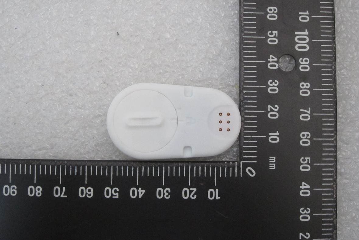
2AI5QTB0001
Nov 10, 2020Thermometer Module
Equipment Class
DXX - Part 15 Low Power Communication Device Transmitter