2AI5QTB0001Thermometer Module
Taiwan Aulisa Medical Devices Technologies, Inc.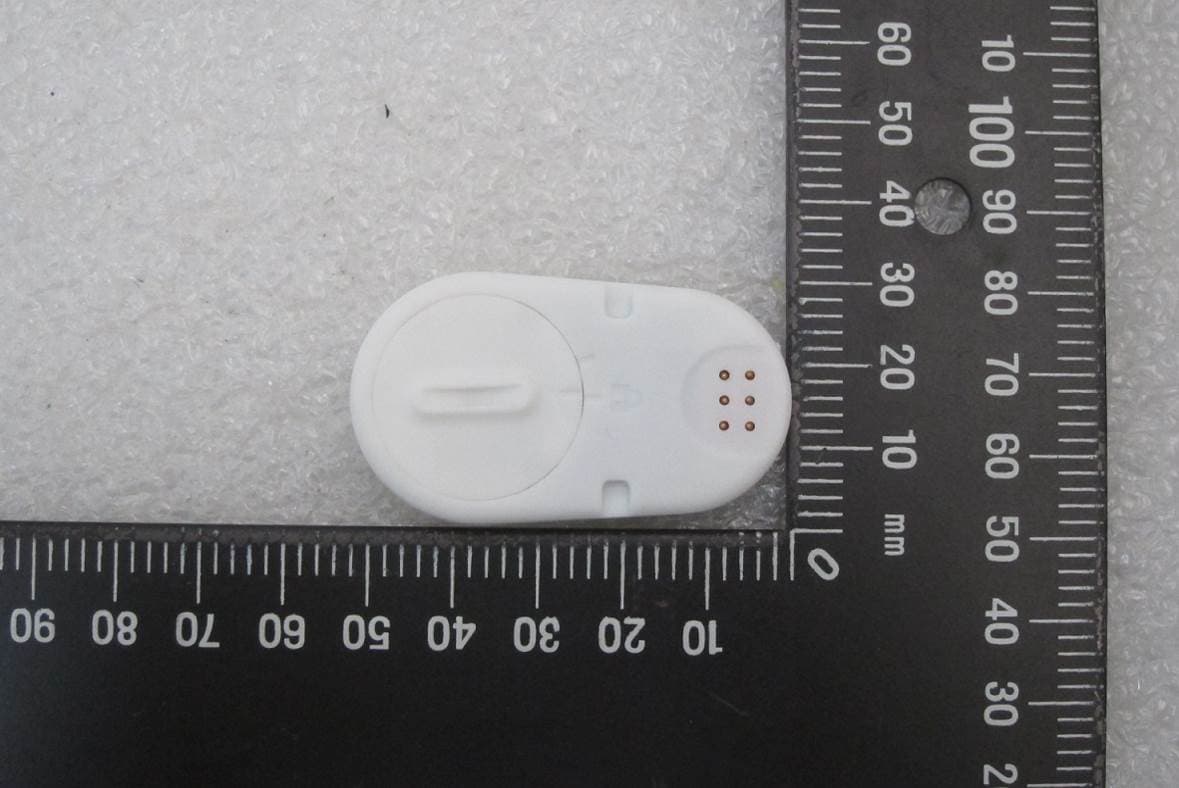
Click to zoom
Application Details
- Equipment Class
- DXX - Part 15 Low Power Communication Device Transmitter
- Date of Grant
- Nov 10, 2020
- Application Purpose
- Original Equipment
- Date of Application
- Nov 10, 2020
- Equipment Note
- Thermometer Module
- Frequency Range
- 2402.00000000 - 2480.00000000
- Country
- Taiwan
Documents & Files
Document Text
Text extracted from the exhibit documents filed with the FCC. Open a document above to read the original.
Users Manual
Instructions For Use ____________________________________________________________ 7MN00025-01 Guardian Angel ® Rx Thermometer Module 1 Disclaimer At the time of publication, this manual is believed to be accurate and up-to-date. In the interest of continued product development, Taiwan Aulisa Medical Devices Technologies, Inc. reserves the right to make changes and improvements to this manual and the products described within at any time, without notice or obligation. References to “Aulisa” in this manual shall imply Taiwan Aulisa Medical Devices Technologies, Inc. Aulisa is a registered trademark of Taiwan Aulisa Medical Devices Technologies, Inc. Taiwan Aulisa Medical Devices Technologies, Inc. No. 218-2, Chong Yang Rd., Nangang Dist. 11573 Taipei City , Taiwan Tel.: +886 809 083 100 Distributed by Aulisa Medical USA, Inc. 999 Commercial Street, Suite 208 Palo Alto, CA 94303,USA Tel.: 1.833.828.5472 www.aulisa.com © 2020 Taiwan Aulisa Medical Devices Technologies, Inc. CAUTION!!! Read this entire manual carefully before using Guardian Angel® Rx Digital Vital Sign Monitoring System. 2 Table of Contents Disclaimer ....................................................................................................................... 1 Guide to Symbols ........................................................................................................... 3 Welcome ........................................................................................................................ 5 Precautions for Use ........................................................................................................ 5 Device Overview ............................................................................................................ 7 Device Components ............................................................................................... 7 Device Description ................................................................................................. 7 Device Intended Use .............................................................................................. 8 Device Principle of Operation ................................................................................ 8 Device Setting Up ........................................................................................................... 9 Device Pairing ............................................................................................................... 11 Automatic Pairing ................................................................................................. 11 Manual Pairing ..................................................................................................... 11 Device Power Off.......................................................................................................... 12 Device Battery Replacement ........................................................................................ 12 Normal Body Temperature Ranges .............................................................................. 13 Alarm ............................................................................................................................ 13 Care and Maintenance ................................................................................................. 13 Cleaning ................................................................................................................ 13 Troubleshooting ........................................................................................................... 15 Manufacturer’s Declaration ......................................................................................... 16 FCC Compliance ........................................................................................................... 19 Service, Support, and Warranty ................................................................................... 21 Privacy Policy ................................................................................................................ 22 Our Policy ............................................................................................................. 22 Changes ................................................................................................................ 23 Specifications ............................................................................................................... 30 Parts and Accessories ................................................................................................... 31 3 Guide to Symbols 4 5 Welcome This manual will help you get started with monitoring using the Thermometer Module of Aulisa Guardian Angel® Rx Digital Vital Sign Monitoring System. GA1000 Series The Thermometer Module is intended for use with the Display Unit. Refer to the GA1000 Series Instructions for Use (7MN00021-01) for detailed instructions. GA2000 Series The Thermometer Module is intended for use with the Display Unit and Receiver/Transponder. Refer to the GA2000 Series Instructions for Use (7MN00022- 01) for detailed instructions. Precautions for Use 1. Any form of modifi cation to this device is forbidden. 2. Do not use this device in an MRI or CT environment. 3. It is intended only as an adjunct in patient assessment and must be used in conjunction with other methods of assessing clinical signs and symptoms. 4. Do not use the device on wounded or irritated skin. In case of skin discomfort, remove the device immediately. 5. It is recommended for indoor use only 6. The device is to be worn under the armpit. Exposure to ambient temperature may cause inaccurate temperature readings. 7. Do not submerge the device in the water or any other liquid. 8. Do not use this device while taking a shower. 9. Do not excessively bend or twist the device. 10. Be careful with small parts that can be removed from the device and swallowed, such as battery cover. They are hazardous to children. 11. …
Text truncated - open the document above for the full version.
External Photos
FCC ID: 2AI5QTB0001 International Standards Laboratory Corp. Report Number: ISL-20LR200FC EUT 1 EUT 2 FCC ID: 2AI5QTB0001 International Standards Laboratory Corp. Report Number: ISL-20LR200FC EUT 3 EUT 4 FCC ID: 2AI5QTB0001 International Standards Laboratory Corp. Report Number: ISL-20LR200FC EUT 5 EUT 6 FCC ID: 2AI5QTB0001 International Standards Laboratory Corp. Report Number: ISL-20LR200FC EUT 7
ID Label/Location Info
GA-TB0001 Thermometer Box FCC ID: 2AI5QTB0001 Label
Internal Photos
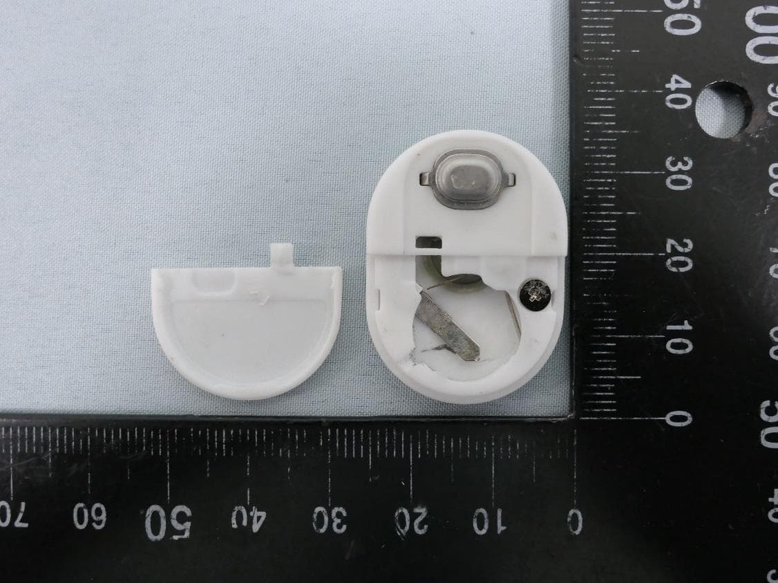
FCC ID: 2AI5QTB0001 International Standards Laboratory Corp. Report Number: ISL-20LR200FC EUT 8 EUT 9 FCC ID: 2AI5QTB0001 International Standards Laboratory Corp. Report Number: ISL-20LR200FC EUT 10 EUT 11 FCC ID: 2AI5QTB0001 International Standards Laboratory Corp. Report Number: ISL-20LR200FC EUT 12 EUT 13 ~ End of Report ~
Test Report
Page: 1 of 26 TEST REPORT of FCC Part 15 Subpart C New Application; Class I PC; Class II PC Product : Thermometer Module Brand: AULISA Model: GA-TM0001 Model Difference: N/A FCC ID: 2AI5QTB0001 FCC Rule Part: §15.249 Applicant: Taiwan Aulisa Medical Devices Technologies, Inc. Address: 10F., No.3-2, YuanQu St., Nangang Dist., Taipei City, Taiwan Test Performed by: International Standards Laboratory Corp. <LT Lab.> *Site Registration No. BSMI: SL2-IN-E-0013; MRA TW0997; TAF: 0997; IC: IC4067B-4 ; *Address: No. 120, Lane 180, Hsin Ho Rd. Lung-Tan Dist., Tao Yuan City 325, Taiwan *Tel : 886-3-407-1718; Fax: 886-3-407-1738 Report No.: ISL-20LR200FC Issue Date : 2020/09/11 Test results given in this report apply only to the specific sample(s) tested and are traceable to national or international standard through calibration of the equipment and evaluating measurement uncertainty herein. The uncertainty of the measurement does not include in consideration of the test result unless the customer required the determination of uncertainty via the agreement, regulation or standard document specification. This test report shall not be reproduced except in full, without the written approval of International Standards Laboratory Corp. -2 of 26- FCC ID: 2AI5QTB0001 International Standards Laboratory Corp. Report Number: ISL-20LR200FC VERIFICATION OF COMPLIANCE Applicant: Taiwan Aulisa Medical Devices Technologies, Inc. Product Description: Thermometer Module Brand Name: AULISA Model No.: GA-TM0001 Model Difference: N/A FCC ID: 2AI5QTB0001 Date of test: 2020/08/25 ~ 2020/09/09 Date of EUT Received: 2020/08/25 We hereby certify that: All the tests in this report have been performed and recorded in accordance with the standards described above and performed by an independent electromagnetic compatibility consultant, International Standards Laboratory Corp. The test results contained in this report accurately represent the measurements of the characteristics and the energy generated by sample equipment under test at the time of the test. The sample equipment tested as described in this report is in compliance with the limits of above standards. Test By: Date: 2020/09/10 Kevin Yao / Senior Engineer Prepared By: Date: 2020/09/10 Elisa Chen / Senior Engineer Approved By: Date: 2020/09/10 Jerry Liu / Technical Manager -3 of 26- FCC ID: 2AI5QTB0001 International Standards Laboratory Corp. Report Number: ISL-20LR200FC Version Version No. Date Description 00 2020/09/10 Initial creation of document Uncertainty of Measurement Description Of Test Uncertainty Conducted Emission (AC power line) 2.586 dB Field Strength of Spurious Radiation ≤30MHz: 2.96dB 30-1GHz: 4.22 dB 1-40 GHz: 4.08 dB Conducted Power 2.412 GHz: 1.30 dB 5.805 GHz: 1.55 dB Power Density 2.412 GHz:1.30 dB 5.805 GHz: 1.67 dB Frequency 0.0032% Time 0.01% DC Voltage 1% -4 of 26- FCC ID: 2AI5QTB0001 International Standards Laboratory Corp. Report Number: ISL-20LR200FC Table of Contents 1. GENERAL INFORMATION ........................................................................................... 5 1.1. PRODUCT DESCRIPTION ................................................................................................................... 5 1.2. RELATED SUBMITTAL(S) / GRANT (S) .............................................................................................. 6 1.3. TEST METHODOLOGY ....................................................................................................................... 6 1.4. TEST FACILITY ................................................................................................................................. 6 1.5. SPECIAL ACCESSORIES ..................................................................................................................... 6 1.6. EQUIPMENT MODIFICATIONS ........................................................................................................... 6 2. SYSTEM TEST CONFIGURATION .............................................................................. 7 2.1. EUT CONFIGURATION ...................................................................................................................... 7 2.2. EUT EXERCISE ................................................................................................................................. 7 2.3. TEST PROCEDURE ............................................................................................................................. 7 2.4. LIMITATION ...................................................................................................................................... 8 2.5. CONFIGURATION OF TESTED SYSTEM ............................................................................................ 10 3. SUMMARY OF TEST RESULTS ................................................................................. 11 4. CONDUCTED EMISSIONS TEST ............................................................................... 12 4.1 MEASUREMENT PROCEDURE: ........................................................................................................ 12 4.2 TEST SET-UP (BLOCK DIAGRAM OF CONFIGURATION) ................................................................ 12 4.3 MEASUREMENT EQUIPMENT USED: ............................................................................................... 12 4.4 MEASUREMENT RESULT: ............................................................................................................... 12 5. RADIATED EMISSION TEST ...................................................................................... 13 5.1 MEASUREMENT PROCEDURE.......................................................................................................... 13 5.2 TEST SET-UP (BLOCK DIAGRAM OF CONFIGURATION) ................................................................ 13 5.3 MEASUREMENT EQUIPMENT USED: ........................................................................…
Text truncated - open the document above for the full version.
Test Setup Photos
FCC ID: 2AI5QTB0001 International Standards Laboratory Corp. Report Number: ISL-20LR200FC Radiated Emission Setup Photos (below 1G) FCC ID: 2AI5QTB0001 International Standards Laboratory Corp. Report Number: ISL-20LR200FC Radiated Emission Setup Photos (above 1G) FCC ID: 2AI5QTB0001 International Standards Laboratory Corp. Report Number: ISL-20LR200FC Radiated Emission Setup Photos
Contact Information
Applicant
Augustine Lien
Test Firm
International Standards Laboratory Corp.Benson Chen
Technical Specifications
| # | Rule Parts | Frequency Range | Power Output |
|---|---|---|---|
| 1 | 15C | 2.40 GHz - 2.48 GHz | - |
Other Applications from Taiwan Aulisa Medical Devices Technologies, Inc.
2AI5QTM0002
Feb 04, 2024Temperature Module
Equipment Class
DTS - Digital Transmission System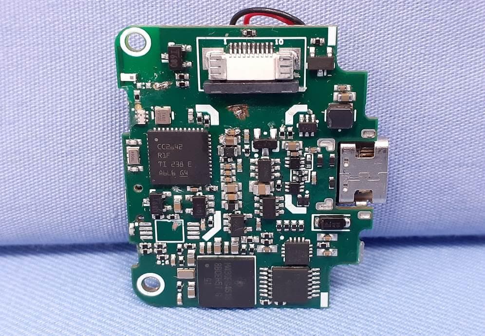
2AI5QOB0005
Apr 22, 2023Oximeter Box with Bluetooth
Equipment Class
DTS - Digital Transmission System
2AI5QOB0006
Apr 09, 2023Infant Oximeter Box with Bluetooth
Equipment Class
DTS - Digital Transmission System
2AI5QGA-RT0001
Feb 01, 2020Receiver/Transponder
Equipment Class
DTS - Digital Transmission System