2AIRP-858922Sky Rover Knight Force
ALPHA GROUP CO., LTD.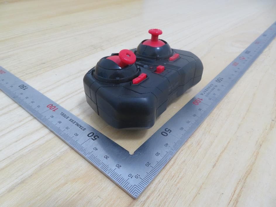
Click to zoom
Application Details
- Equipment Class
- DXX - Part 15 Low Power Communication Device Transmitter
- Date of Grant
- Mar 15, 2021
- Application Purpose
- Original Equipment
- Date of Application
- Mar 15, 2021
- Equipment Note
- Sky Rover Knight Force
- Frequency Range
- 2409.00000000 - 2468.00000000
- Company
- ALPHA GROUP CO., LTD.
- Country
- China
Documents & Files
Document Text
Text extracted from the exhibit documents filed with the FCC. Open a document above to read the original.
Users Manual
1920 22 23 21 21-2 21-3 A B C I J D E F GH 8+ AGES·ÂGE·EDADES US858921/US858922 • Keep these instructions for future reference as they contain important information. • Conservez ces instructions pour référence future car elles contiennent des informations importantes. • Guarde estas instrucciones para consultarlas en el futuro como referencia, ya que contienen información importante. SKY ROVER VIGILANTE 2.4 GHz Radio Control Helicopter Hélicoptère radiocommandé 2,4 GHz Helicóptero de radiocontrol de 2.4 GHz INDOOR/OUTDOOR | STABLE AND EASY CONTROL | UP TO 6 MINUTES OF FLIGHT TIME INTÉRIEUR/EXTÉRIEUR | CONTRÔLE STABLE ET FACILE | JUSQU'À 6 MINUTES DE VOL INTERIOR/EXTERIOR | CONTROL ESTABLE Y FÁCIL | HASTA 6 MINUTOS DEL TIEMPO DE VUELO 21-4 1.USB Charging Cable 2.Main Blade a 3.Main Blade b 6.Balance Bar 7.Main Blade a 8.Main Blade b 9.Tail Blade 10.Landing Gear 11.Power Switch 12.Charing Socket 13.Throttle Lever 14.Speed mode 15.Power switch(OFF-A-B) 16.Steering Lever 17.Power light 18.Left/Right Trimmer x 1 x 1 x 1 x 1 x 2 4.Tail Blade 5.Fastener ■ Full function : Rise, Fall, Turn Left, Turn Right, Forward, Backward, Stop. ■ Power supply : 3 AAA (LR03) alkaline batteries for remote controller ( Batteries sold separately), built-in high-performance lipo battery for helicopter. ■ Flight height : 6 meters ■ Remote control distance : ≥10 meters ■ Flight time : ≥6 minutes Pack List : (Fig.A) Components : (Fig.B & C) Functions and Specifications : Contents and overview Assembly instructions Remote Control Battery Installation : (Fig.D) Locate the locking screw on the back of the controller and remove it from the battery cover(Fig.18) , insert 3 AAA (LR03) batteries in correct polarity(Fig.19), and then close the battery cover(Fig.20). Reinstall locking screw to secure the battery door. Charging helicopter : (Fig.E) Adult supervision is required when charging the helicopter. USB charging:(Fig.21) Move the power switch on the helicopter to the “OFF” position.(Fig.21-2) Insert the USB Port on your PC. Connect the charging cable to the socket on the underside of the helicopter. There is a recessed side on the charging socket (Fig.21-4). When inserted correctly, the raised triangle shape on the Charing Cable (Fig.21-3) lines up with this recessed side of the charging socket and the light on the USB will illuminate. The charging time is about 60 minutes. When your helicopter is fully charged, the light will turn off. Flying the helicopter : Adult supervision is recommended when flying the helicopter. Move the power switch on the helicopter to the “ON” position and place the helicopter on a flat surface. Move the power switch on the controller to the “ON” position. Push the throttle lever all way up and down. You can see the LEDs on Heli and Remote change the status from fast flash to be long light to indicate successful pairing. Up and Down : (Fig.F) When the helicopter flies steadily, you can slowly push the throttle lever up to make helicopter fly higher, or release the lever a bit to make helicopter fly lower. Only small lever position changes are required for smooth flying. Rotation : (Fig .G) Hold the helicopter at a steady height. Push the steering lever towards left to turn counter clockwise, and push the steering lever towards right to turn clockwise. Forward & Backward : (Fig .H) When you push the steering lever up, the helicopter moves forward; when you push the steering lever down, the helicopter moves backward. If the helicopter rotates while in operation, please use the lever trim to adjust. (Fig .I) (Fig.22). If the helicopter spins counter clockwise, you can press the trim button to the right until the helicopter stops spinning. (Fig.23). If the helicopter spins clockwise, you can press the trim button to the left until the helicopter stops spinning. Attention: If the helicopter spins during forward or backward operation or constantly wobbles while in flight mode, check the blades for damage or warping. Blades replacement:(Fig.J) Adult supervision is required when replacing the helicopter blades. -remove the screws that lock down the damaged blade or blades to replace them. -remove the damaged blade or blades, check that they are proper marked blades. (check underneath the blade will be marked AA or BB). -reinstall locking screw to lock down the blades. -To remove a damaged tail propeller gently up on the propeller until it is removed. -To install a new tail propeller, fist align the bottom of the propeller opening with the motor pin and press on the top of the propeller until it is completely down. There should not be any of the motor pin exposed. Environment for flight: It is recommended to fly in a space area over 20ft(W)*30ft(L)*10ft(H). Fly in a wide-open room away from breakable items. Avoid flying near vents and/or fans, these may overpower the aircraft and make it difficult to control. Make sure there are no obstacles that will interfere with flight causing potential danger and/or electrical hazards. A flat surface is required, or smart hovering height will be affected. Important safety information: Adult supervision advised. Keep away from obstacles and electrical hazards. Actual product styling and/or color may vary. Carefully open packages with safety scissors to avoid damaging product. Please retain package and instructions for important information. Please remove all packaging materials before giving to children. If rotors become damaged or broken, do not fly. Flying with broken rotors may damage helicopter and/or lead to injury. FOR LED PRODUCTS: It is rare but possible for seizures to be triggered by light flashes. To reduce exposure to such potential,do not flash lights directly into eyes. FCC Statement: This equipment has been tested and found to comply with the limits for a Class B digital device, pursuant to Part 15 of the FCC Rules. These limits are designed to provide reasonable protection against harmful interference in a residential installation. This equipment …
Text truncated - open the document above for the full version.
External Photos
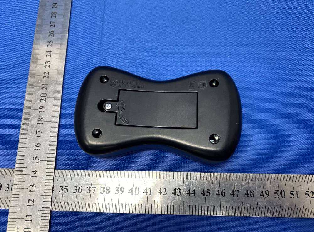
Appendix I External Photographs Page 2 of 3 UL Verification Services (Guangzhou) Co., Ltd, Song Shan Lake Branch This report shall not be reproduced except in full, without the written approval of UL Verification Services (Guangzhou) Co., Ltd, Song Shan Lake Branch. View of EUT-1 View of EUT-2 Page 3 of 3 UL Verification Services (Guangzhou) Co., Ltd, Song Shan Lake Branch This report shall not be reproduced except in full, without the written approval of UL Verification Services (Guangzhou) Co., Ltd, Song Shan Lake Branch. View of EUT-3 View of EUT-4
ID Label/Location Info
FCC ID: 2AIRP-858922 IC: 22295-858922 Model No.: US858922
Internal Photos
Appendix II Internal Photographs Page 2 of 3 UL Verification Services (Guangzhou) Co., Ltd, Song Shan Lake Branch This report shall not be reproduced except in full, without the written approval of UL Verification Services (Guangzhou) Co., Ltd, Song Shan Lake Branch. Internal View of EUT-1 Internal View of EUT-2 RF ANT Page 3 of 3 UL Verification Services (Guangzhou) Co., Ltd, Song Shan Lake Branch This report shall not be reproduced except in full, without the written approval of UL Verification Services (Guangzhou) Co., Ltd, Song Shan Lake Branch. Internal View of EUT-3
Test Report
The results reported herein have been performed in accordance with the laboratory’s terms of accreditation. This report shall not be reproduced except in full without the written approval of the Laboratory. The results in this report apply to the test sample(s) mentioned above at the time of the testing period only and are not to be used to indicate applicability to other similar products. CFR 47 FCC PART 15 SUBPART C ISED RSS-210 ISSUE 10 TEST REPORT For Sky Rover Knight Force MODEL NUMBER: US858922 FCC ID: 2AIRP-858922 IC: 22295-858922 REPORT NUMBER: 4789856042-1 ISSUE DATE: March 12, 2021 Prepared for ALPHA GROUP CO., LTD. ALPHA ANIMATION INDUSTRIAL AREA,JINHONG ROAD EAST & FENGXIANG ROAD NORTH,CHENGHAI DISTRICT, SHANTOU, GUANGDONG,P.R.CHINA Prepared by UL Verification Services (Guangzhou) Co., Ltd, Song Shan Lake Branch Building 10, Innovation Technology Park, No. 1, Li Bin Road, Song Shan Lake Hi- Tech Development Zone Dongguan, 523808, People’s Republic of China Tel: +86 769 22038881 Fax: +86 769 33244054 Website: www.ul.com REPORT NO.: 4789856042-1 Page 2 of 50 UL Verification Services (Guangzhou) Co., Ltd, Song Shan Lake Branch FORM NO.: 10-SL-F0058 This report shall not be reproduced except in full, without the written approval of UL Verification Services (Guangzhou) Co., Ltd, Song Shan Lake Branch. Revision History Rev. Issue Date Revisions Revised By V0 03/12/2021 Initial Issue REPORT NO.: 4789856042-1 Page 3 of 50 UL Verification Services (Guangzhou) Co., Ltd, Song Shan Lake Branch FORM NO.: 10-SL-F0058 This report shall not be reproduced except in full, without the written approval of UL Verification Services (Guangzhou) Co., Ltd, Song Shan Lake Branch. Summary of Test Results Clause Test Items FCC/ISED Rules Test Results 1 20dB Bandwidth and 99% Occupied Bandwidth CFR 47 FCC §15.215 (c) ISED RSS-Gen Clause 6.7 Pass 2 Radiated Emission CFR 47 FCC §15.249 (a)(d)(e) ISED RSS-210 Annex B B.10 CFR 47 FCC §15.205 and §15.209 RSS-GEN Clause 8.9 RSS-GEN Clause 8.10 Pass 3 Antenna Requirement CFR 47 FCC §15.203 ISED RSS-Gen Clause 6.3 Pass Note 1: This test report is only published to and used by the applicant, and it is not for evidence purpose in China. Note 2: The measurement result for the sample received is <Pass> according to < CFR 47 FCC PART 15 SUBPART C, ISED RSS-210 Issue 10 and ISED RSS-GEN Issue 5 > when <Accuracy Method> decision rule is applied. REPORT NO.: 4789856042-1 Page 4 of 50 UL Verification Services (Guangzhou) Co., Ltd, Song Shan Lake Branch FORM NO.: 10-SL-F0058 This report shall not be reproduced except in full, without the written approval of UL Verification Services (Guangzhou) Co., Ltd, Song Shan Lake Branch. TABLE OF CONTENTS 1. ATTESTATION OF TEST RESULTS ................................................................................ 5 2. TEST METHODOLOGY .................................................................................................... 6 3. FACILITIES AND ACCREDITATION ................................................................................ 6 4. CALIBRATION AND UNCERTAINTY ............................................................................... 7 4.1. MEASURING INSTRUMENT CALIBRATION .............................................................. 7 4.2. MEASUREMENT UNCERTAINTY .............................................................................. 7 5. EQUIPMENT UNDER TEST .............................................................................................. 8 5.1. DESCRIPTION OF EUT ............................................................................................. 8 5.2. MAXIMUM FIELD STRENGTH ................................................................................... 8 5.3. CHANNEL LIST.......................................................................................................... 8 5.4. DESCRIPTION OF AVAILABLE ANTENNAS .............................................................. 9 5.5. TEST CHANNEL CONFIGURATION .......................................................................... 9 5.6. THE WORSE CASE POWER SETTING PARAMETER ............................................... 9 5.7. TEST ENVIRONMENT ............................................................................................... 9 5.8. DESCRIPTION OF TEST SETUP ............................................................................. 10 5.9. MEASURING INSTRUMENT AND SOFTWARE USED............................................. 11 6. ANTENNA PORT TEST RESULTS ................................................................................. 12 6.1. ON TIME AND DUTY CYCLE ................................................................................... 12 6.2. 20 dB BANDWIDTH AND 99% OCCUPIED BANDWIDTH ........................................ 14 7. RADIATED TEST RESULTS .......................................................................................... 18 7.1. LIMITS AND PROCEDURE ...................................................................................... 18 7.2. RESTRICTED BANDEDGE AND FIELD STRENGTH OF INTENTIONAL EMISSIONS 25 7.3. SPURIOUS EMISSIONS (1~3GHz) .......................................................................... 31 7.4. SPURIOUS EMISSIONS (3~18GHz) ........................................................................ 37 7.5. SPURIOUS EMISSIONS (18~26GHz) ...................................................................... 43 7.6. SPURIOUS EMISSIONS BELOW 30MHz ................................................................. 45 7.7. SPURIOUS EMISSIONS BELOW 1GHz AND ABOVE 30MHz .................................. 48 8. ANTENNA REQUIREMENTS.......................................................................................... 50 REPORT NO.: 4789856042-1 Page 5 of 50 UL Verification Services (Guangzhou) Co., Ltd, Song Shan Lake Branch FORM NO.: 10-SL-F0058 This report shall not be reproduced except in full, without the written approval of UL Verification Serv…
Text truncated - open the document above for the full version.
Test Setup Photos
Appendix II Setup Photographs RADIATED RF MEASUREMENT SETUP (30MHz ~ 1 GHz) RADIATED RF MEASUREMENT SETUP (Below 30MHz) RADIATED RF MEASUREMENT SETUP (Above 1G – X axis) RADIATED RF MEASUREMENT SETUP (Above 1G – Y axis) RADIATED RF MEASUREMENT SETUP (Above 1G – Z axis)
Contact Information
Applicant
xinyue xu(Quality Manager)
Technical Contact
UL Verification Services (Guangzhou) Co., Ltd.Susan Liu
BLDG 10 INNOVATION TECHNOLOGY PARK NO 1 LIN BIN RD · Dongguan · China
Test Firm
UL Verification Services (Guangzhou) Co., Ltd.Stephen Guo
[email protected]+86 0769 33817120
Technical Specifications
| # | Rule Parts | Frequency Range | Power Output |
|---|---|---|---|
| 1 | 15C | 2.41 GHz - 2.47 GHz | - |
Other Applications from ALPHA GROUP CO., LTD.
2AIRP-389111
Jul 04, 2022RC Cyclone Emergency Car
Equipment Class
DXX - Part 15 Low Power Communication Device Transmitter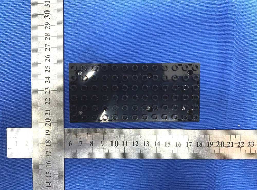
2AIRP-389112
Jul 04, 2022RC Cyclone Emergency Car
Equipment Class
DXX - Part 15 Low Power Communication Device Transmitter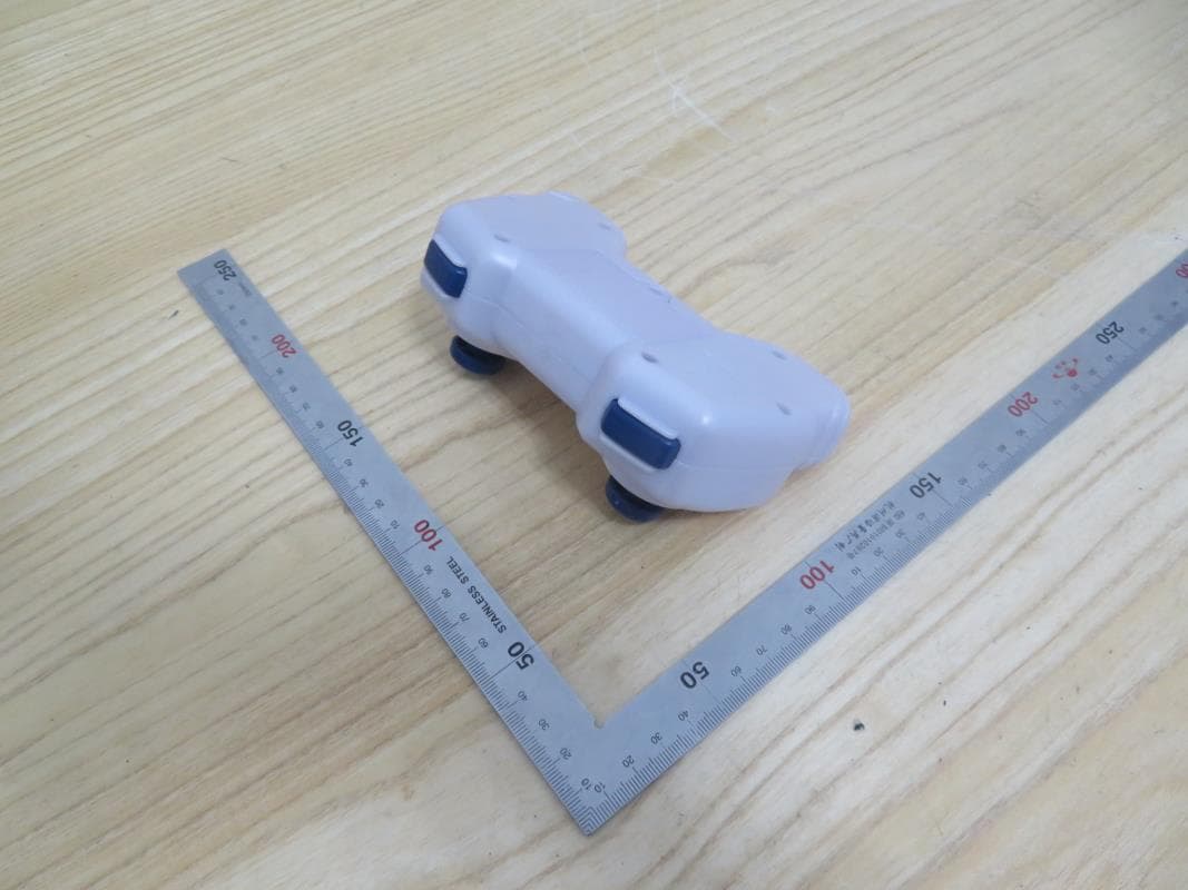
2AIRP-858350
Jul 28, 2021TERRA WHEEL
Equipment Class
DXX - Part 15 Low Power Communication Device Transmitter
2AIRP-858951
Apr 23, 2021SKY Rover KING
Equipment Class
DXX - Part 15 Low Power Communication Device Transmitter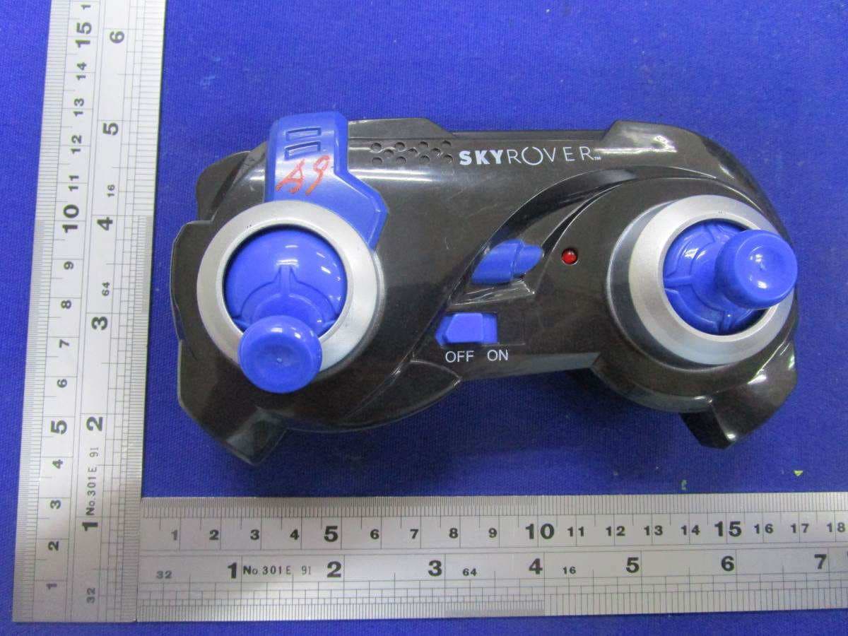
2AIRP-858952
Oct 18, 2020Sky Rover-White Sky Rover King
Equipment Class
DXX - Part 15 Low Power Communication Device Transmitter