2AITNTOUCHFINDTouchFind with Bluetooth
Powerstick.com Inc.
Click to zoom
Application Details
- Equipment Class
- DTS - Digital Transmission System
- Date of Grant
- Jul 12, 2021
- Application Purpose
- Original Equipment
- Date of Application
- Jul 12, 2021
- Equipment Note
- TouchFind with Bluetooth
- Frequency Range
- 2402.00000000 - 2480.00000000
- Company
- Powerstick.com Inc.
- Country
- Canada
Documents & Files
Document Text
Text extracted from the exhibit documents filed with the FCC. Open a document above to read the original.
Users Manual
TouchFind User Guide FCC ID: 2AITNTOUCHFIND 1. Before You Start Here are a few important points you should know before getting started with your TouchFind. A. The Spot app MUST be running in the background of your phone to communicate with your TouchFind finder. B. A maximum of 4 TouchFind finders can be connected to one mobile device at a time. C. TouchFind finders can only be paired to ONE mobile device at a time. D. The Bluetooth on your device must always be ON. 2. Getting Started A. Download the “Spot” app from iTunes or Google Play. B. Remove the plastic tab from the TouchFind unit. Wait 10 seconds for the battery to fully activate. C. Push the button on the TouchFind, you should hear a beep from the TouchFind unit. D. From your device, make sure Bluetooth is turned ON. 3. Pair Your Spot A. Open the App Open the app on your mobile device. Press PAIR A TouchFind. B. Pair Your TouchFind As instructed in the app, press & hold the TouchFind button for about 2 seconds. Select your TouchFind from the list of nearby Spots. C. Choose Mode Choose between Tether Mode and Find Mode. These are different options that will determine how you use your TouchFind. Tap on TETHER MODE or FIND MODE. Continue reading for more information on each mode. 4. Tether Mode Uses for Tether Mode Tether Mode is convenient if you’re the type of person who often leaves things behind. Forgot your phone on the counter when leaving for work or forgot your keys in a restaurant? Once out of range, your devices will emit an audio alert as a reminder to go back and get your forgotten item. Additionally, Tether Mode can provide a security alarm. If someone were to take your phone orTouchFind out of range without you noticing, your devices would emit audio alerts. This notifies you as well as causes the stolen item to emit an alarm. Tether Mode Alerts A. How it Works Tether Mode creates an invisible link between your mobile device and your TouchFind. Both items are “in range” when within approximately 120 feet of each other. If either item becomes “out of range”, the invisible link is broken, which causes both your mobile device and TouchFind to emit an audio alert. A. How it Works Once you hear the audio alert, the mobile device and TouchFind must be brought back in range of each other for the alert to TouchFind. B. Alarm Toggles Tether Mode lets you control whether your TouchFind, your mobile device, or both will emit an audio alarm when they are out of range. C. Proximity Meter This meter shows you how close you are to your TouchFind when you are in range. If all five dots are green, you are right beside your Spot. If your Spot is out of range, the proximity meter will disappear. D. Camera Your TouchFind also allows you to remotely control the shutter of your phone’s camera. Set up a great shot from a distance or a creative angle and don’t worry about reaching for the shutter button on your phone. SEE ADVANCED SECTION 9A-B TO LEARN MORE 5. Find Mode Uses for Find Mode Find Mode is for you if you often find yourself wondering where you left your phone or rushing around the house to find your keys before you leave. Find Mode makes sure you’re never without your most important items. A. Finding Your TouchFind If you have misplaced your Spot, and the item it is attached to, simply open the Spot app on your mobile device and tap FIND. The TouchFind will emit an audio alert allowing you to easily find it. As you search, the proximity meter will help you know if you are getting closer to or further from the TouchFind. B. Finding Your Phone Find Mode also works in reverse. If you have misplaced your phone but have your TouchFind, simply press and hold the TouchFind button for 2-3 seconds. Your mobile device will emit a loud audio alert, making it simple to find. C. Proximity Meter This meter shows you how close you are to your TouchFind when you are in range. If all five dots are green, you are right beside your Spot. If your TouchFind is out of range, the proximity meter will disappear. SEE ADVANCED SECTION 4D TO LEARN MORE Camera Feature D. Camera Your TouchFind also allows you to remotely control the shutter of your phone’s camera. Set up a great shot from a distance or a creative angle and don’t worry about reaching for the shutter button on your phone. SEE ADVANCED SECTION 9A-B TO LEARN MORE 6. Settings & Management A. Settings Press the TouchFind icon at the top of the app screen, or SETTINGS FOR THIS SPOT at the bottom of the screen for more options and to switch between Find and Tether Mode. B. Switch Modes & Other Options From the settings menu, you can rename your Spot, switch between modes, choose a label for your TouchFind, create Quiet Places and Quiet Times and remove the TouchFind. SEE ADVANCED SECTION 7D-E TO LEARN MORE C. Menu On the main Spot app screen, tap the Menu button in the top left corner for more TouchFind options. D. Menu Options In this menu you can silence your Spots, pair a new TouchFind, or link to the Support page. ADVANCED Back to top 1. Downloading the app You must first download the App in order to use your TouchFind Bluetooth finder. Simply search for “Spot” in your mobile device’s app store. Only iOS and Android devices are supported. (iOS 6.0 or later & Android 4.2.2 or later) Note: Despite operating system requirements, certain Android devices have different limitations that can affect app compatibility. 2. Preparing Your TouchFind A. Remove the plastic tab blocking the TouchFind battery. B. Wait 10 seconds for the battery to activate. C. Push and hold the TouchFind button for 2-3 seconds. You should hear a beep. D. Make sure that your Bluetooth is on in your mobile device. 3. Pairing Your TouchFind A. Pairing Your First TouchFind Open the “Spot” app. During the initial set-up, the app will initiate the pairing of your first TouchFind. Tap on PAIR A BEAGLE. Make sure Bluetooth is enabled. Press and hold the button on your TouchFind for 2-3 seconds to pair. B. Pairing Additional TouchFinds …
Text truncated - open the document above for the full version.
External Photos
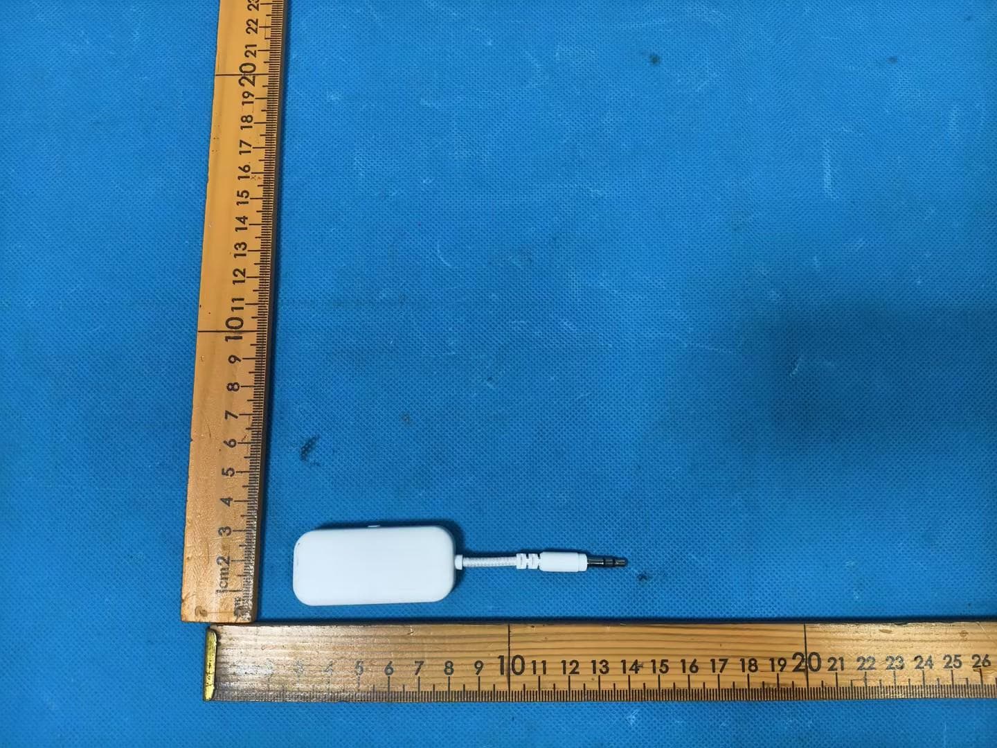
Annex No.: BL-SZ2130570-AW 1 / 3 EUT EXTERNAL PHOTOS FRONT VIEW OF EUT b REAR VIEW OF EUT Annex No.: BL-SZ2130570-AW 2 / 3 LEFT SIDE VIEW OF EUT RIGHT SIDE OF EUT X Annex No.: BL-SZ2130570-AW 3 / 3 TOP VIEW OF EUT c BOTTOM VIEW OF EUT
ID Label/Location Info
Label: Label location Brand Name:Powerstick Model:TouchFind FCC ID:2AITNTOUCHFIND Label
Internal Photos
Annex No.: BL-SZ2130570-AI 1 / 3 EUT INTERNAL PHOTOS EUT UNCOVER VIEW EUT UNCOVER VIEW Annex No.: BL-SZ2130570-AI 2 / 3 MAIN BOARD TOP VIEW MAIN BOARD REAR VIEW RF Chip Ceramic Antenna Annex No.: BL-SZ2130570-AI 3 / 3 Battery Photo (FRONT) Battery Photo (REAR)
RF Exposure Info
RF Exposure Evaluation for FCC ID: 2AITNTOUCHFIND Refer user manual this device is a TouchFind, and this device was designed used in portable devices that the minimum distance between human’s body is 5mm. Based on the 47CFR 2.1093, this device belongs to portable device. The definition of the category as following: Portable Derives: CFR Title 47 §2.1093(b) (b) For purposes of this section, a portable device is defined as a transmitting device designed to be used so that the radiating structure(s) of the device is/are within 20 centimeters of the body of the user. FCC KDB 447498 D01 General RF Exposure Guidance v06 Limit Unless specifically required by the published RF exposure KDB procedures, standalone 1-g head or body and 10-g extremity SAR evaluation for general population exposure conditions, by measurement or numerical simulation, is not required when the corresponding SAR Test Exclusion Threshold condition, listed below, is satisfied. These test exclusion conditions are based on source-based time-averaged maximum conducted output power of the RF channel requiring evaluation, adjusted for tune-up tolerance, and the minimum test separation distance required for the exposure conditions. The minimum test separation distance is determined by the smallest distance from the antenna and radiating structures or outer surface of the device, according to the host form factor, exposure conditions and platform requirements, to any part of the body or extremity of a user or bystander. The 1-g and 10-g SAR test exclusion thresholds for 100 MHz to 6 GHz at test separation distances ≤ 50 mm are determined by: [(max. power of channel, including tune-up tolerance, mW) / (min. test separation distance, mm)] · [√f(GHz) ] ≤ 3.0 for 1-g SAR and ≤ 7.5 for 10-g extremity SAR Where • f (GHz) is the RF channel transmit frequency in GHz • Power and distance are rounded to the nearest mW and mm before calculation • The result is rounded to one decimal place for comparison The test exclusions are applicable only when the minimum test separation distance is ≤ 50 mm and for transmission frequencies between 100 MHz and 6 GHz. When the minimum test separation distance is < 5 mm, a distance of 5 mm is applied to determine SAR test exclusion. Test data Bluetooth Mode GFSK (BLE) Low Channel Middle Channel High Channel Peak Power (dBm) -7.92 -7.34 -7.00 Note: This report listed the worst case peak power value, please refer to RF test report for more details. Turn-up power Mode Power Range (dBm) Bluetooth -6.50-(-8.00) RF Exposure Evaluation Result Mode Tune-up limit power (dBm) Distance (mm) Calculation Frequency (MHz) Calculation Results Threshold Value Verdict Bluetooth -6.50 5 2480 0.071 3.0 Compliance --END OF REPORT--
Test Report
Report No.: BL-SZ2130570-601 2 / 50 Revision History Version Issue Date Revisions Content Rev. 01 Jun. 17, 2021 Initial Issue Rev. 02 Jun. 23, 2021 Update the Brand Name is Powerstick.com TABLE OF CONTENTS 1 ADMINISTRATIVE DATA (GENERAL INFORMATION) .......................................................................... 5 1.1 Identification of the Testing Laboratory ....................................................................................... 5 1.2 Identification of the Responsible Testing Location ...................................................................... 5 1.3 Laboratory Condition ................................................................................................................... 5 1.4 Announce .................................................................................................................................... 5 2 PRODUCT INFORMATION ...................................................................................................................... 6 2.1 Applicant Information ................................................................................................................... 6 2.2 Manufacturer Information ............................................................................................................ 6 2.3 Factory Information ..................................................................................................................... 6 2.4 General Description for Equipment under Test (EUT) ................................................................ 6 2.5 Technical Information .................................................................................................................. 7 2.6 Additional Instructions ................................................................................................................. 8 3 SUMMARY OF TEST RESULTS .............................................................................................................. 9 3.1 Test Standards ............................................................................................................................ 9 3.2 Verdict ......................................................................................................................................... 9 4 GENERAL TEST CONFIGURATIONS ................................................................................................... 10 4.1 Test Environments .................................................................................................................... 10 4.2 Test Equipment List ................................................................................................................... 10 4.3 Measurement Uncertainty ......................................................................................................... 11 4.4 Description of Test Setup .......................................................................................................... 12 4.4.1 For Antenna Port Test ............................................................................................................... 12 4.4.2 For AC Power Supply Port Test ................................................................................................ 12 4.4.3 For Radiated Test (Below 30 MHz) ........................................................................................... 13 4.4.4 For Radiated Test (30 MHz-1 GHz) .......................................................................................... 13 4.4.5 For Radiated Test (Above 1 GHz) ............................................................................................. 14 4.5 Measurement Results Explanation Example ............................................................................. 15 4.5.1 For conducted test items: .......................................................................................................... 15 Report No.: BL-SZ2130570-601 3 / 50 4.5.2 For radiated band edges and spurious emission test: ............................................................... 15 5 TEST ITEMS ........................................................................................................................................... 16 5.1 Antenna Requirements .............................................................................................................. 16 5.1.1 Relevant Standards ................................................................................................................... 16 5.1.2 Antenna Anti-Replacement Construction .................................................................................. 16 5.1.3 Antenna Gain ............................................................................................................................ 16 5.2 Output Power ............................................................................................................................ 17 5.2.1 Test Limit ................................................................................................................................... 17 5.2.2 Test Setup ................................................................................................................................. 17 5.2.3 Test Procedure .......................................................................................................................... 17 5.2.4 Test Result ................................................................................................................................ 18 5.3 Occupied Bandwidth ................................................................................................................. 19 5.3.1 Limit ........................................................................................................................................... 19 5.3.2 Test Setup ..............................................................................................................................…
Text truncated - open the document above for the full version.
Test Setup Photos
Annex No.: BL-SZ2130570-AR 1 / 3 TEST SETUP PHOTOS 1 Radiated Test Photo Below 30MHz 30MHz-1GHz Annex No.: BL-SZ2130570-AR 2 / 3 Close-up Above 1GHz Annex No.: BL-SZ2130570-AR 3 / 3 Close-up 2 Conducted Test Photo Conducted Test
Contact Information
Applicant
John Zhu
Test Firm
Shenzhen BALUN Technology Co., Ltd.Hanson Lin
[email protected]86-755-66833830
Technical Specifications
| # | Rule Parts | Frequency Range | Power Output |
|---|---|---|---|
| 1 | 15C | 2.40 GHz - 2.48 GHz | 200.00 µW |
Other Applications from Powerstick.com Inc.
2AITN-FLYTE
Aug 11, 2026FLYTE
Equipment Class
DTS - Digital Transmission System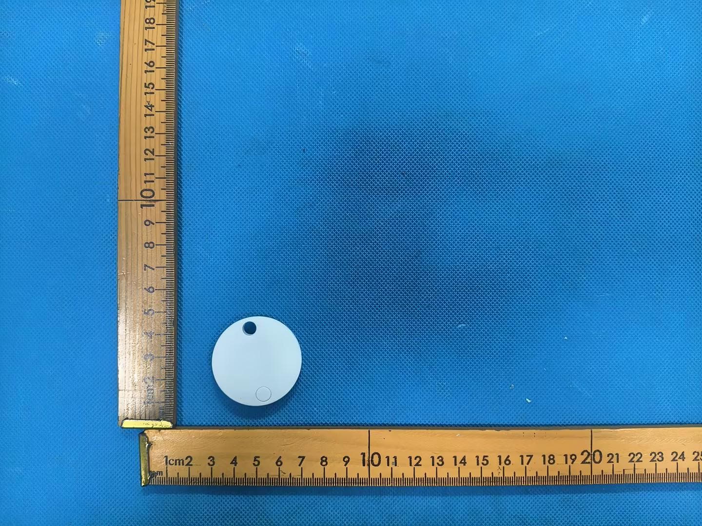
2AITN-SPOTCDN
Apr 20, 2026Spot
Equipment Class
DTS - Digital Transmission System
2AITN-POWERSTATION
Oct 10, 2024Powerstation
Equipment Class
DCD - Part 15 Low Power Transmitter Below 1705 kHz
2AITN-POWERMAG
Aug 27, 2024PowerMag
Equipment Class
DCD - Part 15 Low Power Transmitter Below 1705 kHz2AITN-HYPERNOVA
Aug 23, 2024HyperNova
Equipment Class
DCD - Part 15 Low Power Transmitter Below 1705 kHz