2AJIV-MF8375CREATIVE STAGE V2
Creative Labs Pte. Ltd.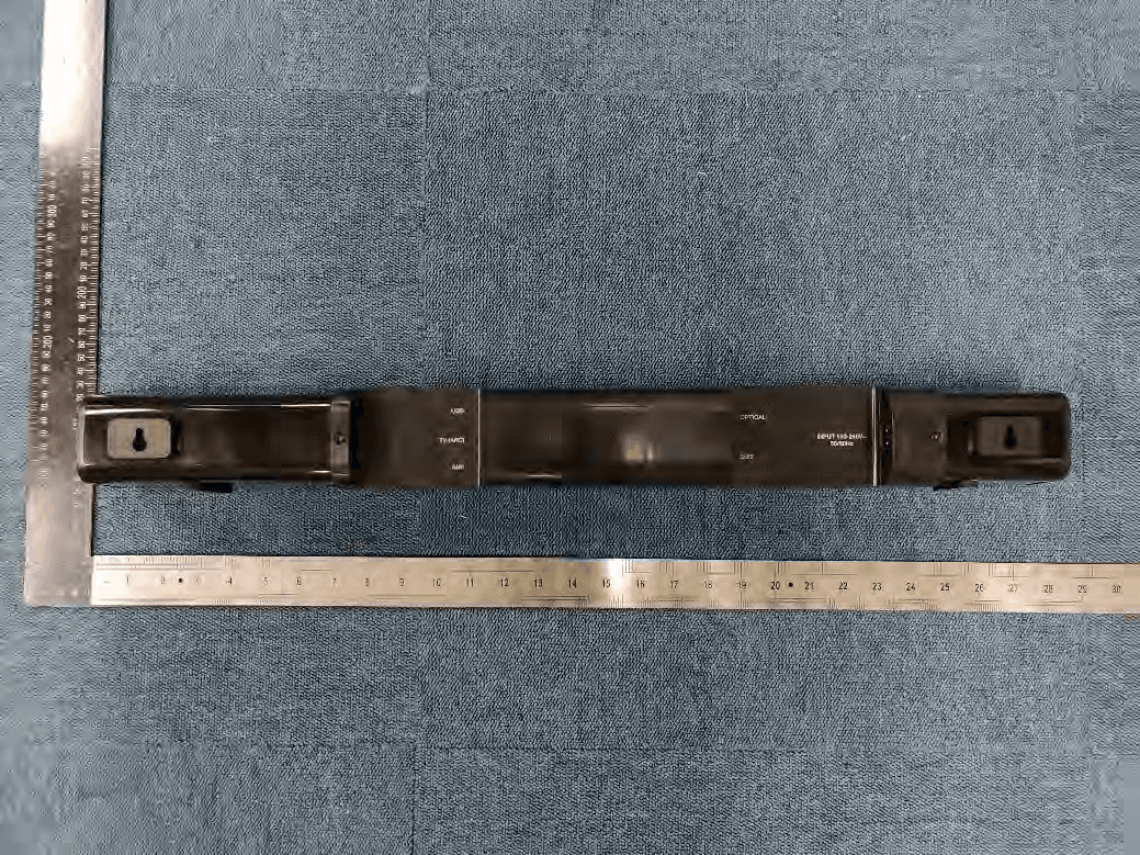
Click to zoom
Application Details
- Equipment Class
- DSS - Part 15 Spread Spectrum Transmitter
- Date of Grant
- Sep 20, 2020
- Application Purpose
- Original Equipment
- Date of Application
- Sep 20, 2020
- Equipment Note
- CREATIVE STAGE V2
- Frequency Range
- 2402.00000000 - 2480.00000000
- Company
- Creative Labs Pte. Ltd.
- Country
- Singapore
Documents & Files
Document Text
Text extracted from the exhibit documents filed with the FCC. Open a document above to read the original.
Users Manual
130x7=910 200x2=400 PN: 03MF837500000 Rev A 使用产品前请阅读使用说明 Model No. / 型號 / 型号: MF8375 Quick Start Guide © 2020 Creative Technology Ltd. All rights reserved. Creative and the Creative logo are trademarks or registered trademarks of Creative Technology Ltd in the United States and/or other countries. The Bluetooth® word mark and logo are owned by the Bluetooth SIG, Inc. and any use of such marks by Creative Technology Ltd is under license. All other trademarks are the property of their respective owners and are hereby recognized as such. All specifications are subject to change without notice. Actual product may differ slightly from images shown. Use of this product is subject to a limited warranty. REGISTER YOUR PRODUCT www.creative.com/register TECHNICAL SUPPORT www.creative.com/support 1. Overview STAGE V2 2.1 High-performance Soundbar with Subwoofer 4. Bluetooth Mode / Power-saving Mode Bluetooth Pairing Mode Press and hold the Bluetooth button on either the soundbar or IR remote control for 2s to enter Bluetooth Pairing mode. Built-in LED will start blinking in blue. Select “Stage V2” from the list of discovered Bluetooth devices to pair. Once paired with a device, soundbar’s LED will remain blue in static state. Creative Stage V2 will automatically connect to last paired device when in Bluetooth mode. To pair to a new device, press and hold 2s to enter Bluetooth Pairing mode again. Press the Bluetooth button once to exit Bluetooth Pairing mode. Clearing Soundbar’s Bluetooth Memory In Bluetooth mode, press and hold the Bluetooth button on either the soundbar or IR remote control for 8s to clear all previously paired devices. Soundbar will return to Bluetooth mode once completed. Power-saving Mode Creative Stage V2 features a power-saving mode that will power off the soundbar after more than 24 hours of inactivity. To activate / deactivate this feature, press and hold the power button for 10s when the soundbar is powered off. A Subwoofer D E F USB-C Port TV (ARC) Port AUX-in K L M Volume + Button Power Button Volume - Button G H Optical-in Port To Subwoofer BC J N I LED DisplayLED Indicator Wall Mount Brackets Bluetooth ® Button AC IN 2. IR Remote Control a j k l m n o p b c d e f g h i *AAA batteries not included a b c d e f g h i Power Button Press and hold 2s to power off soundbar LED Indicator Mute Button Press once to mute volume Press once again to unmute volume TV (ARC) Source Button Press once to toggle to TV (ARC)-out source Press once again to toggle to USB-out source OPT Source Button Press once to toggle to Optical-out source Press once again to toggle to AUX-out source Bluetooth Source Button Press once to enter Bluetooth Mode Press and hold for 2s to enter Bluetooth Pairing mode Volume + Button Press to increase volume Volume - Button Press to decrease volume j k l m n o p Play / Pause Button Press once to play Press once again to pause (Applicable in USB and Bluetooth modes only) Previous Track Button Press once to return to previous track (Applicable in USB and Bluetooth modes only) Next Track Button Press once to skip to next track (Applicable in USB and Bluetooth modes only) Surround Button Press once to turn on Surround mode Press once again to turn off Surround mode Reset Button Press to reset all audio settings Clear Dialog Button Press once to turn on Clear Dialog mode Press once again to turn off Clear Dialog mode Bass / Treble - / + Button Press to increase / decrease Bass / Treble’s value Bass Treble Button Press to toggle between Bass and Treble Bluetooth Version: Bluetooth 5.0 Operating Frequency: 2402–2480 MHz Operating Range: Up to 10m / 33 ft, measured in open space. Walls and structures may affect range of device RF Output Power: < 4 dBm Supported Bluetooth Profiles: A2DP (Wireless Stereo Bluetooth), AVRCP (Bluetooth Remote Control) Supported Codec: SBC Input: 100–240V 50 / 60 Hz 1.5A Speaker Power: 20W x 2, Satellite, 40W Subwoofer, Peak 160W Frequency Response: 55–20,000 Hz SNR: ≥ 75 dB Operating Temperature Range: 0–45ºC Please visit creative.com/compliance/Stagev2 for the user guide, safety and regulatory information, and ErP information where applicable. Please visit creative.com/support/Stagev2 for all other support related to your product. 7. Technical Specification Other Information i) Wall Mount Brackets 560 mm / 22.05” ii) Screw into wall ^ Screws not included. Sold separately 6. Wall Mount b c 3. Source Selection and Display Press the respective buttons on the provided IR remote control to select preferred audio source. Alternatively, press once on the soundbar’s power button to cycle through sources: Bluetooth > Optical > TV (ARC) > USB Audio > AUX – AUX-in – Bluetooth Mode – Optical-in – TV (ARC) Mode – USB Audio Mode – Standby – Clear Dialog On – Clear Dialog Off – Surround On – Surround Off – Bass – Treble 5. TV (ARC) / Optical / AUX Connectivity iv) Optical Cable * 1. TV Audio Output: Optical 2. Digital Audio format: PCM iv) i) USB-C to USB-A Cable ii) TV (ARC) Cable * 1. TV Audio Output: ARC 2. Digital Audio format: PCM iii) AUX Cable * Not included. Sold separately i) ii) iii) ARC a 【EN】 The use of the WEEE Symbol indicates that this product may not be treated as household waste. By ensuring this product is disposed of correctly, you will help protect the environment. For more detailed information about the recycling of this product, please contact your local authority, your household waste disposal service provider or the shop where you purchase the product. 【FR】 L’utilisation du symbole DEEE indique que ce produit ne peut être traîté comme déchet ménager. En garantissant la mise au rebut appropriée de ce produit, vous contribuez à préserver l’environnement. Pour plus d’informations sur le recyclage de ce produit, contactez les autorités locales, le fournisseur de service d’élimination des déchets ménagers ou le magasin où vous avez acheté le produit. 【DE】 Die Verwendung des WEEE-Symbols gibt an, dass dieses Produkt nicht als Haushaltsmü…
Text truncated - open the document above for the full version.
Cover Letter(s)
Agent Authorization Company: CREATIVE LABS PTE. LTD. Address: 31 International Business Park #03-01 Singapore 609921 Product Name: CREATIVE STAGE V2 Model Number(s): MF8375 Product Description: CREATIVE STAGE V2 with Bluetooth We authorize MiCOM Labs Inc., 575 Boulder Court, Pleasanton, California 94566, USA, to act on our behalf on all matters concerning the certification of above named equipment. We declare that MiCOM Labs Inc. is allowed to forward all information related to the approval and certification of equipment to the regulatory agencies as required and to discuss any issues concerning the approval application. Any and all acts carried out by MiCOM Labs on our behalf shall have the same effect as acts of our own. Signature: Date: 2020-09-16 Name: Toh Mary Title: REGULATORY MANAGER Company: CREATIVE LABS PTE. LTD.
Cover Letter(s)
Date: 2 September 2020 CREATIVE LABS PTE. LTD. To: Federal Communications Commission, Authorization & Evaluation Division, 7435 Oakland Mills Road, Columbia, MD 21046 To Whom It May Concern: The CREATIVE LABS PTE. LTD., the undersigned, hereby authorizes Mr. Wu Xuewen from Shenzhen BALUN Technology Co., Ltd., to act on the behalf of the CREATIVE LABS PTE. LTD. solely in matters relating to the application for an FCC equipment authorization for FCC ID: 2AJIV-MF8375 including the signing of documents in connection with this Application. Necessary acts carried out by Shenzhen BALUN Technology Co., Ltd. in connection with the Application shall have the same effect as acts of the CREATIVE LABS PTE. LTD.. The CREATIVE LABS PTE. LTD. also hereby certify that no party to this application is subject to a denial of benefits, including FCC benefits, pursuant to Section 5301 of the Anti-Drug Abuse Act of 1988, 21 U.S.C. Section 862. Yours Sincerely, _______ Toh Mary
Cover Letter(s)
Date: 2 September 2020 CREATIVE LABS PTE. LTD. To: Federal Communications Commission, Authorization & Evaluation Division, 7435 Oakland Mills Road, Columbia, MD 21046 Re: CREATIVE LABS PTE. LTD. FCC ID: 2AJIV-MF8375 FCC Certification Confidentiality Request Gentlemen: This letter is to comply with 47 CFR 0.457 and 0.459 pertaining to confidentiality material. CREATIVE LABS PTE. LTD. requests that the following documents regarding this submission for FCC ID: 2AJIV-MF8375 be kept confidential: Exhibit Type File Name Block Diagram Block Diagram.pdf Schematics Schematics.pdf Operational Description Operational Description.pdf And below exhibit kept short-term confidential (180 days): External photos External photos.pdf Test setup photos test photo.pdf Internal photos Internal photos.pdf User manual User manual.pdf Those documents contain detailed system and equipment description and related information about the product which CREATIVE LABS PTE. LTD. considers to be confidential proprietary, a custom design and, otherwise, not releasable to the general public. Since this design is a basis form which future technological products will evolve, CREATIVE LABS PTE. LTD. considers this information would be of benefit to its competitors, and that the disclosure of the information in these documents would give competitors an unfair advantage in the market. Yours Sincerely, Toh Mary
External Photos
Annex No.: BL-SZ2080161-AW 1 / 9 EUT EXTERNAL PHOTOS Soundbar FRONT VIEW OF EUT REAR VIEW OF EUT Annex No.: BL-SZ2080161-AW 2 / 9 LEFT SIDE VIEW OF EUT RIGHT SIDE OF EUT Annex No.: BL-SZ2080161-AW 3 / 9 TOP VIEW OF EUT BOTTOM VIEW OF EUT Annex No.: BL-SZ2080161-AW 4 / 9 Subwoofer FRONT VIEW OF EUT REAR VIEW OF EUT Annex No.: BL-SZ2080161-AW 5 / 9 LEFT SIDE VIEW OF EUT RIGHT SIDE OF EUT Annex No.: BL-SZ2080161-AW 6 / 9 TOP VIEW OF EUT BOTTOM VIEW OF EUT Annex No.: BL-SZ2080161-AW 7 / 9 Accessory-Remote Control Accessory-Remote Control Annex No.: BL-SZ2080161-AW 8 / 9 Accessory-USB Cable Accessory-AUX Cable Annex No.: BL-SZ2080161-AW 9 / 9 Accessory-Power Line(US Plug)
ID Label/Location Info
Label Location
Internal Photos
Annex No.: BL-SZ2080161-AI 1 / 4 EUT INTERNAL PHOTOS Soundbar EUT UNCOVER VIEW MAIN BOARD TOP VIEW RF Module PCB Antenna Annex No.: BL-SZ2080161-AI 2 / 4 MAIN BOARD REAR VIEW SECONDARY BOARD 1 TOP VIEW Annex No.: BL-SZ2080161-AI 3 / 4 SECONDARY BOARD 1 REAR VIEW SECONDARY BOARD 2 TOP VIEW Annex No.: BL-SZ2080161-AI 4 / 4 SECONDARY BOARD 2 REAR VIEW Subwoofer EUT UNCOVER VIEW
RF Exposure Info
RF Exposure Evaluation for FCC ID: 2AJIV-MF8375 Refer user manual this device is a CREATIVE STAGE V2, and this device was designed used in Mobile devices that the minimum distance between human’s body is 20cm. Based on the 47CFR 2.1091, this device belongs to Mobile device. The definition of the category as following: Mobile Derives: CFR Title 47 §2.1091(b) (b) For purposes of this section, a mobile device is defined as a transmitting device designed to be used in other than fixed locations and to generally be used in such a way that a separation distance of at least 20 centimeters is normally maintained between the transmitter’s radiating structure(s) and the body of the user or nearby persons. FCC KDB 447498 D01 General RF Exposure Guidance v06 Limit Devices operating in standalone mobile exposure conditions may contain a single transmitter or multiple transmitters that do not transmit simultaneously. A minimum test separation distance ≥ 20 cm is required between the antenna and radiating structures of the device and nearby persons to apply mobile device exposure limits. The distance must be fully supported by the operating and installation configurations of the transmitter and its antenna(s), according to the source-based time- averaged maximum power requirements of § 2.1091(d)(2). In cases where cable losses or other attenuations are applied to determine compliance, the most conservative operating configurations and exposure conditions must be evaluated. The minimum test separation distance required for a device to comply with mobile exposure conditions must be clearly identified in the installation and operating instructions, for all installation and exposure conditions, to enable users and installers to comply with RF exposure requirements. For mobile devices that have the potential to operate in portable device exposure conditions, similar to the configurations described in § 2.1091(d)(4), a KDB inquiry is required to determine the SAR test requirements for demonstrating compliance. When the categorical exclusion provision of § 2.1091(c) applies, the minimum test separation distance may be estimated, when applicable, by simple calculations according to plane-wave equivalent conditions, to ensure the transmitter and its antenna(s) can operate in manners that meet or exceed the estimated distance. The source-based time-averaged maximum radiated power, according to the maximum antenna gain, must be applied to calculate the field strength and power density required to establish the minimum test separation distance. When the estimated test separation distance becomes overly conservative and does not support compliance, MPE measurement or computational modeling may be used to determine the required minimum separation distance. According to FCC Part 1.1307, systems operating under the provisions of this section shall be operated in a manner the ensures that the public is not exposed to radio frequency energy level in excess of the commission’s guidelines. Limits for General Population/ Uncontrolled Exposure Frequency Range (MHz) Electric Field Strength(E)(V/m) Magnetic Field Strength (H)(A/m) Power Density (S)(mW/cm 2 ) 0.3-1.34 614 1.63 (100)* 1.34-30 824/f 2.19/f (180/f2)* 30-300 27.5 0.073 0.2 300-1500 f/1500 1500-100,000 1.0 MPE calculation formula Where: S = power density P = output power (mW) G = power gain of the antenna in the direction of interest relative to an isotropic radiator R = Separation distance between radiator and human body (cm) Test data Bluetooth Mode BR+EDR GFSK ∏/4-DQPSK 8-DPSK Peak Power (dBm) -4.03 -1.40 -1.17 Note: This report listed the worst case peak power value, please refer to RF test report for more details. Turn-up power Mode Range (dBm) Bluetooth (-5.00)-(-1.00) Test result Evolution mode Maximum peak output power (dBm) Antenna Gain (typical) (dBi): Total Power (mw) Distance (cm) Limit of Power Density (mW/cm²) Power Density (mW/cm²) Verdict Bluetooth -1.00 2.88 1.54 20 1 0.0003 Pass Note: 1. The CREATIVE STAGE V2 work frequency range used is 2400 MHz ~ 2483.5 MHz, the result close to the limit by the above formula. 2. More power list please refer to RF test report. Conclusion: RF exposure Evaluation Results: Compliance
Test Report
Report No.: BL-SZ2080161-601 2 / 74 Revision History Version Issue Date Revisions Content Rev. 01 Sep. 11, 2020 Initial Issue TABLE OF CONTENTS 1 ADMINISTRATIVE DATA (GENERAL INFORMATION) .......................................................................... 5 1.1 Identification of the Testing Laboratory ....................................................................................... 5 1.2 Identification of the Responsible Testing Location ...................................................................... 5 1.3 Laboratory Condition ................................................................................................................... 5 1.4 Announce .................................................................................................................................... 6 2 PRODUCT INFORMATION ...................................................................................................................... 7 2.1 Applicant Information ................................................................................................................... 7 2.2 Manufacturer Information ............................................................................................................ 7 2.3 Factory Information ..................................................................................................................... 7 2.4 General Description for Equipment under Test (EUT) ................................................................ 7 2.5 Technical Information .................................................................................................................. 8 2.6 Additional Instructions ................................................................................................................. 9 3 SUMMARY OF TEST RESULTS ............................................................................................................ 10 3.1 Test Standards .......................................................................................................................... 10 3.2 Verdict ....................................................................................................................................... 11 4 GENERAL TEST CONFIGURATIONS ................................................................................................... 12 4.1 Test Environments .................................................................................................................... 12 4.2 Test Equipment List ................................................................................................................... 12 4.3 Measurement Uncertainty ......................................................................................................... 13 4.4 Description of Test Setup .......................................................................................................... 14 4.4.1 For Antenna Port Test ............................................................................................................... 14 4.4.2 For AC Power Supply Port Test ................................................................................................ 14 4.4.3 For Radiated Test (Below 30 MHz) ........................................................................................... 15 4.4.4 For Radiated Test (30 MHz-1 GHz) .......................................................................................... 15 4.4.5 For Radiated Test (Above 1 GHz) ............................................................................................. 16 4.5 Measurement Results Explanation Example ............................................................................. 17 4.5.1 For conducted test items: .......................................................................................................... 17 Report No.: BL-SZ2080161-601 3 / 74 5 TEST ITEMS ........................................................................................................................................... 18 5.1 Antenna Requirements .............................................................................................................. 18 5.1.1 Relevant Standards ................................................................................................................... 18 5.1.2 Antenna Anti-Replacement Construction .................................................................................. 18 5.1.3 Antenna Gain ............................................................................................................................ 18 5.2 Frequency Hopping Systems .................................................................................................... 19 5.2.1 Relevant Standards ................................................................................................................... 19 5.2.2 Description of the systems ........................................................................................................ 19 5.3 Number of Hopping Frequencies .............................................................................................. 21 5.3.1 Limit ........................................................................................................................................... 21 5.3.2 Test Setup ................................................................................................................................. 21 5.3.3 Test Procedure .......................................................................................................................... 21 5.3.4 Test Result ................................................................................................................................ 21 5.4 Peak Output Power and E.I.R.P ................................................................................................ 22 5.4.1 Test Limit ....................................................................…
Text truncated - open the document above for the full version.
Test Setup Photos
Annex No.: BL-SZ2080161-AR 1 / 4 TEST SETUP PHOTOS 1 Radiated Test Photo Below 30MHz 30MHz-1GHz Annex No.: BL-SZ2080161-AR 2 / 4 Close-up Above 1GHz Annex No.: BL-SZ2080161-AR 3 / 4 Close-up 2 Conducted Test Photo Conducted Test-BT3.0 Annex No.: BL-SZ2080161-AR 4 / 4 3 Conducted Emissions Test Photo 1 Test Photo 2
Contact Information
Applicant
Stephen Choong
Technical Contact
Test Firm
Shenzhen BALUN Technology Co., Ltd.Hanson Lin
[email protected]86-755-66833830
Technical Specifications
| # | Rule Parts | Frequency Range | Power Output |
|---|---|---|---|
| 1 | 15C | 2.40 GHz - 2.48 GHz | 760.00 µW |
Other Applications from Creative Labs Pte. Ltd.
2AJIV-MF1730
Jul 02, 2026Creative XF1
Equipment Class
DTS - Digital Transmission System2AJIV-EF1220
Aug 28, 2024Creative Zen Hybrid Gen 2
Equipment Class
DSS - Part 15 Spread Spectrum Transmitter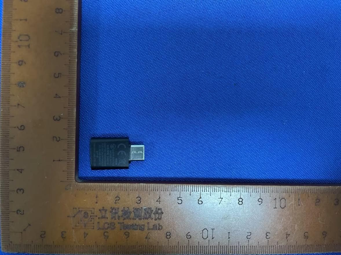
2AJIV-SA0210
Jul 28, 2024Creative BT-W6
Equipment Class
DSS - Part 15 Spread Spectrum Transmitter2AJIV-EF1180
Jul 01, 2024Creative Zen Air SXFI
Equipment Class
DSS - Part 15 Spread Spectrum Transmitter
2AJIV-EF1090
Sep 26, 2023Creative Zen Air Pro
Equipment Class
DTS - Digital Transmission System