2AJVQ-MT7601UBWLAN module
Qingdao Intelligent&Precise Electronics Co.,Ltd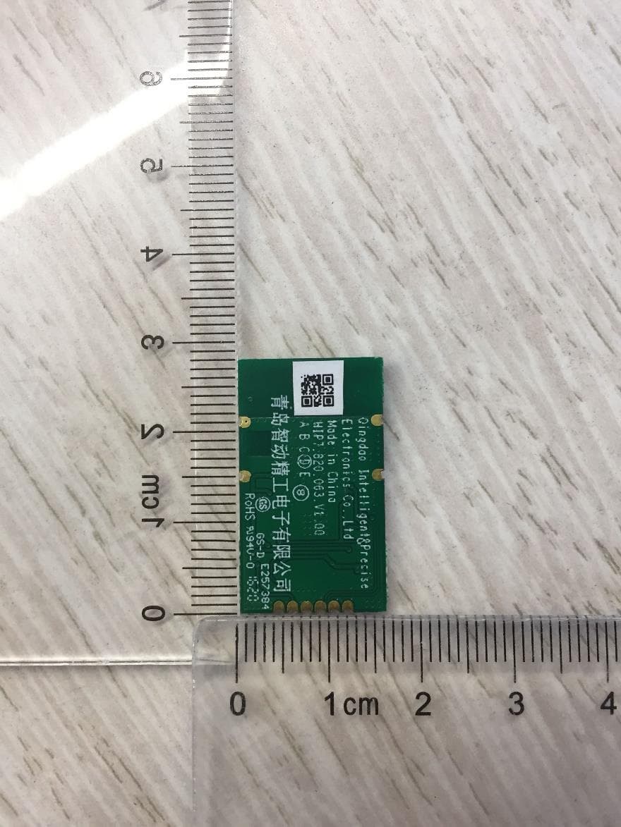
Click to zoom
Application Details
- Equipment Class
- DTS - Digital Transmission System
- Date of Grant
- May 27, 2020
- Application Purpose
- Original Equipment
- Date of Application
- May 20, 2020
- Equipment Note
- WLAN module
- Frequency Range
- 2412.00000000 - 2462.00000000
- Country
- China
Documents & Files
Document Text
Text extracted from the exhibit documents filed with the FCC. Open a document above to read the original.
Users Manual
Qingdao Intelligent & Precise Electronics Co., Ltd ZDGFMT7601U-B User Manual Product Name:IEEE 802.11 b/g/n 2.4GHz 1T1R, USB Module Model :ZDGFMT7601U-B 1 1. Introduction Thank you for using the Wi-Fi module product provided by Qingdao Intelligent &Precise Electronics Co., Ltd. Before use, please read this user manual carefully. Please follow the technical specifications when using the module in your design and develop activities. Qingdao Intelligent &Precise Electronics Co., Ltd has the right to change the contents of this manual in accordance with the needs of the technical development. FCC application: This device complies with Part 15 of the FCC Rules / Industry Canada licence-exempt RSS standard(s). Operation is subject to the following two conditions: (1) this device may not cause harmful interference, and (2) this device must accept any interference received, including interference that may cause undesired operation. Le présent appareil est conforme aux CNR d'Industrie Canada applicables aux appareils radio exempts de licence. L'exploitation est autorisée aux deux conditions suivantes : (1) l'appareil ne doit pas produire de brouillage, et (2) l'utilisateur de l'appareil doit accepter tout brouillage radioélectrique subi, même si le brouillage est susceptible d'en compromettre le fonctionnement. Changes or modifications not expressly approved by the party responsible for compliance could void the user's authority to operate the equipment. This equipment has been tested and found to comply with the limits for a Class B digital device, pursuant to part 15 of the FCC Rules. These limits are designed to provide reasonable protection against harmful interference in a residential installation. This equipment generates uses and can radiate radio frequency energy and, if not installed and used in accordance with the instructions, may cause harmful interference to radio communications. However, there is no guarantee that interference will not occur in a particular installation. If this equipment does cause harmful interference to radio or television reception, which can be determined by turning the equipment off and on, the user is encouraged to try to correct the interference by one or more of the following measures: —Reorient or relocate the receiving antenna. —Increase the separation between the equipment and receiver. —Connect the equipment into an outlet on a circuit different from that to which the receiver is connected. —Consult the dealer or an experienced radio/TV technician for help. MPE Requirements To satisfy FCC RF exposure requirements, a separation distance of 20 cm or more should be maintained between the antenna of this device and persons during device operation. To ensure compliance, operations at closer than this distance is not recommended. Les antennes installées doivent être situées de facon à ce que la population ne puisse y être exposée à une distance de moin de 20 cm. Installer les antennes de facon à ce que le personnel ne puisse approcher à 20 cm ou moins de la position centrale de l’ antenne. La FCC des éltats-unis stipule que cet appareil doit être en tout temps éloigné d’au moins 20 cm des personnes pendant son functionnement. 2 Region Selection Limited by local law regulations, version for North America does not have region selection option. Label Host labeling requirement: Contains transmitter module FCC ID: 2AJVQ-MT7601UB”. 2.Product Information 2.1 Product Information ZDGFMT7601U-B Wi-Fi USB module is a wireless signal module device work at 2.4GHz (2.400 ~ 2.4835GHz). ZDGFMT7601U-B comply with IEEE 802.11b、802.11 g、802.11 n standard. It supports up to 150Mbps physical layer transmitting rate. ZDGFMT7601U-B support USB 2.0, which has up to 480Mbps data rate. ZDGFMT7601U-B is widely used to multi-media device, such as smart TV. Equipped with ZDGFMT7601U-B, a smart TV could access to Wireless Local Network, which is also called WLAN or WIFI network. ZDGFMT7601U-B helps multi-media device achieve to send & receive data package in a wireless way. 2.2 Feature ●IEEE standard:IEEE 802.11b/g/n client device without radar detection ●operating Frequency 2.4GHz ●support up to 150Mbps ● 1T1R mode ●Support 20MHz, 40MHz width in 2.4GHz band. ●support USB 2.0 high data rate mode ●support WFA/ WPA/WPA2 /WPS2.0/WAPI security ●RoH ●MAC /baseband/RF: MT7601U 3. Product Specification 3.1 Parameter WLAN Standard IEEE802.11b/g/n Data Interface USB2.0 Modulation Mode WIFI: 802.11b:CCK, DQPSK, DBPSK 802.11g:64QAM, 16QAM, QPSK, BPSK 802.11n:64QAM, 16QAM, QPSK, BPSK Working Frequency 2.4G: 2400-2483.5MHz 3 Receiver Sensitivity 11b @ 11Mbps: (Max.) : -84dBm , (Typical) : -87dBm (PER<8%) 11g @ 54Mbps: (Max.) : -69dBm , (Typical) : -75dBm (PER<10%) 11n @ MCS7 (2.4g HT20): (Max.) : -67dBm , (Typical) : -73dBm (PER<10%) 11n @ MCS7 (2.4g HT40): (Max.) : -64dBm , (Typical) : -68dBm (PER<10%) Working Voltage 3.3V±10% I/O supply voltage Antenna Gain 1.02dBi(MAX) Antenna type Onboard Antenna Working Temperature -10~+70°C Storage Temperature -40~+125°C 4. Hardware information 4.1 structure dimension:(Unit:mm) PCB Material:FR-4,Surface treatment:ENIG. Appearance Dimension(mm):16(+/- 0.3)×28(+/- 0.3) PCB thickness:1.0mm(+/-0.15mm). 4.2 PIN definition NO Description 1 +3.3V 2 D- 3 D+ 4 GND 5 Reset 6 Device wake Host function 4.3 Block Diagram MCU MT7601U U2 3.3V 40MHz X1 2.4G Match Circuit ANT PMU Block Diagram 4 5 EU single contact point Hisense Czech (Manufacture) s.r.o. U Nové Hospody 1164/4, 301 00 Plzeň ,Czech Republic. 6 Manufacture’s postal address No.218, Qianwangang Road, Qingdao Economic & Technological Development Zone, Shandong, China 7 Importer’s name & address Hisense Czech (Manufacture) s.r.o. U Nové Hospody 1164/4, 301 00 Plzeň ,Czech Republic. 5 8. The requirement for KDB 996369 D03: 8.1 List of applicable FCC rules FCC Part 15. 247. 8.2 Summarize the specific operational use conditions None 8.3 Limited module procedures The module is a single module, so this requirement is not a…
Text truncated - open the document above for the full version.
Attestation Statements
Qingdao Intelligent&Precise Electronics Co.,Ltd Declaration Letter We Qingdao Intelligent&Precise Electronics Co.,Ltd hereby declare that the product WLAN module is not capable of operating with channel 12 and 13 in regions of US and Canada. Versions of the product available for import and sale in the US and Canada will not operate on channels 12 and 13. It will not be possible for users and configure these channels in the US and Canada version. By: ______________________ Caifeng Li (Signature 1 ) (Print name) Title: Quality Engineer________ On behalf of: Qingdao Intelligent&Precise Electronics Co.,Ltd _________ (Company Name) Telephone: ______86 532 80879444____________________ 1 - Must be signed by applicant contact given for applicant on the FCC site, or by the authorized agent if an appropriate authorized agent letter has been provided. Letters should be placed on appropriate letterhead.
Attestation Statements
THIS MUST BE SIGNED BY THE APPLICANT/AGENT AND SHOULD BE PLACED ON APPROPRIATE LETTERHEAD 053019-02a Request for Modular/Limited Modular Approval Date: May 20, 2020 Subject: Manufacturer’s Declaration for ☒ - Modular Approval ☐ - Split Modular Approval ☐ - Limited Modular Approval ☐ - Limited Split Modular Approval Confidentiality Request for: ______2AJVQ-MT7601UB______ 8 Basic Requirements – FCC Part 15.212(a)(1) For Items Marked “NO(*)”, the Limited Module Description Must be Filled Out on the Following Pages Modular Approval Requirement Requirement Met 1. The modular transmitter must have its own RF shielding. This is intended to ensure that the module does not have to rely upon the shielding provided by the device into which it is installed in order for all modular transmitter emissions to comply with FCC limits. It is also intended to prevent coupling between the RF circuitry of the module and any wires or circuits in the device into which the module is installed. Such coupling may result in non-compliant operation. The physical crystal and tuning capacitors may be located external to the shielded radio elements. 15.212(a)(1)(i) ☒ - YES ☐ - NO(*) Details: < The module contains a metal shield which covers all RF components and circuitry. The shield is located on the top of the board next to antenna connector> 2. The modular transmitter must have buffered modulation/data inputs (if such inputs are provided) to ensure that the module will comply with FCC requirements under conditions of excessive data rates or over-modulation. 15.212(a)(1)(ii) ☒ - YES ☐ - NO(*) Details: < All modulation and data inputs are buffered by circuitry on the transmitter chip U2, as is shown in the schematic.> 3. The modular transmitter must have its own power supply regulation on the module. This is intended to ensure that the module will comply with FCC requirements regardless of the design of the power supplying circuitry in the device into which the module is installed. 15.212(a)(1)(iii) ☒ - YES ☐ - NO(*) Details: <The module contains its own power supply regulation. Please refer to Block Diagram with this application> 4. The modular transmitter must comply with the antenna and transmission system requirements of §§ 15.203, 15.204(b), 15.204(c), 15.212(a), and 2.929(b). The antenna must either be permanently attached or employ a ‘‘unique’’ antenna coupler (at all connections between the module and the antenna, including the cable). The ‘‘professional installation’’ provision of § 15.203 is not applicable to modules but can apply to limited modular approvals under paragraph 15.212(b). 15.212(a)(1)(iv) ☒ - YES ☐ - NO(*) Details: < The antenna is permanently attached.> 5. The modular transmitter must be tested in a stand-alone configuration, i.e., the module must not be inside another device during testing. This is intended to demonstrate that the module is capable of complying with Part 15 emission limits regardless of the device into which it is eventually installed. Unless the transmitter module will be battery powered, it must comply with the AC line conducted requirements found in Section 15.207. AC or DC power lines and data input/output lines connected to the module must not contain ferrites, unless they will be marketed with the module (see Section 15.27(a)). The length of these lines shall be length typical of actual use or, if that length is unknown, at least 10 centimeters to insure that there is no coupling between the case of the module and supporting equipment. Any accessories, peripherals, or support equipment connected to the module during testing shall be unmodified or commercially available (see Section 15.31(i)). 15.212(a)(1)(v) ☒ - YES ☐ - NO(*) Details: <The module was tested stand-alone as shown in test setup photographs filed with this application> THIS MUST BE SIGNED BY THE APPLICANT/AGENT AND SHOULD BE PLACED ON APPROPRIATE LETTERHEAD 053019-02a Modular Approval Requirement Requirement Met 6. The modular transmitter must be labeled with its own FCC ID number, or use an electron display (see KDB Publication 784748). If using a permanently affixed label with its own FCC ID number, if the FCC ID is not visible when the module is installed inside another device, then the outside of the device into which the module is installed must also display a label referring to the enclosed module. This exterior label can use wording such as the following: “Contains Transmitter Module FCC ID: XYZMODEL1” or “Contains FCC ID: XYZMODEL1.” Any similar wording that expresses the same meaning may be used. The Grantee may either provide such a label, an example of which must be included in the application for equipment authorization, or, must provide adequate instructions along with the module which explain this requirement. In the latter case, a copy of these instructions must be included in the application for equipment authorization. If the modular transmitter uses an electronic display of the FCC identification number, the information must be readily accessible and visible on the modular transmitter or on the device in which it is installed. If the module is installed inside another device, then the outside of the device into which the module is installed must display a label referring to the enclosed module. This exterior label can use wording such as the following: “Contains FCC certified transmitter module(s).” Any similar wording that expresses the same meaning may be used. The user manual must include instructions on how to access the electronic display. A copy of these instructions must be included in the application for equipment authorization. 15.212(a)(1)(vi) ☒ - YES ☐ - NO(*) Details: <There is a label on the module as shown in the labeling exhibit filed with this application. Host specific labeling instructions are shown in the installation manual filed with this application.> 7. The modular transmitter must comply with all specific rule or operating requirements applicable to the transmitter,…
Text truncated - open the document above for the full version.
Cover Letter(s)
Qingdao Intelligent&Precise Electronics Co.,Ltd Authority to Act as Agent Date: April 15, 2020 American Certification Body, Inc. 6731 Whittier Avenue Suite C110 McLean, VA 22101 To Whom It May Concern: ______Intertek Testing Services Shanghai______ is authorized to act on our behalf, until otherwise notified, for applications to American Certification Body, Inc. (ACB). We certify that we are not subject to denial of federal benefits, that includes FCC benefits, pursuant to Section 5301 of the Anti-Drug Abuse Act of 1988, 21 U.S.C. 862. Further, no party, as defined in 47 CFR 1.2002 (b), to the application is subject to denial of federal benefits, that includes FCC benefits. Thank you, Agency Agreement Expiration Date: ____ April 15, 2021 ___ By: ________________________ Caifeng Li (Signature 1 ) (Print name) Title: _______ Quality Engineer________ On behalf of: __ Qingdao Intelligent&Precise Electronics Co.,Ltd ________________________ (Company Name) Telephone: ______86 532 80879444____________________ 1 - Must be signed by applicant contact given for applicant on the FCC site, or by the authorized agent if an appropriate authorized agent letter has been provided. Letters should be placed on appropriate letterhead.
Cover Letter(s)
Qingdao Intelligent&Precise Electronics Co.,Ltd Request for Confidentiality Date: __April 15, 2020______ Subject: Confidentiality Request for: 2AJVQ-MT7601UB Pursuant to FCC 47 CFR 0.457(d) and 0.459 and IC RSP-100, Section 9.4, the applicant requests that a part of the subject FCC application be held confidential. Type of Confidentiality Requested Exhibit ☐ Short Term ☒ Permanent Block Diagrams ☐ Short Term External Photos ☐ Short Term ☐ Permanent * 1 Internal Photos ☐ Short Term ☒ Permanent Operation Description/Theory of Operation ☐ Short Term ☐ Permanent Parts List & Placement/BOM ☐ Short Term ☐ Permanent Tune-Up Procedure ☐ Short Term ☒ Permanent Schematics ☐ Short Term Test Setup Photos ☐ Short Term ☐ Permanent * 3 User’s Manual ____ Qingdao Intelligent&Precise Electronics Co.,Ltd ____ has spent substantial effort in developing this product and it is one of the first of its kind in industry. Having the subject information easily available to "competition" would negate the advantage they have achieved by developing this product. Not protecting the details of the design will result in financial hardship. Permanent Confidentiality: The applicant requests the exhibits listed above as permanently confidential be permanently withheld from public review due to materials that contain trade secrets and proprietary information not customarily released to the public. Short-Term Confidentiality: The applicant requests the exhibits selected above as short term confidential be withheld from public view for a period of ___(specify number of days not to exceed 180) 2 ___ days from the date of the Grant of Equipment Authorization and prior to marketing. This is to avoid premature release of sensitive information prior to marketing or release of the product to the public. Applicant is also aware that they are responsible to notify ACB in the event information regarding the product or the product is made available to the public before the requested period has expired. ACB will then release the documents listed above for public disclosure pursuant to FCC Public Notice DA 04-1705. NOTE for Industry Canada Applications: IC currently only distinguishes Permanent Confidentiality exhibits as shown above. Short Term confidentiality is not considered applicable to IC applications. Sincerely, By: __________________________ _______ Caifeng Li__________________ (Signature/Title 3 ) (Print name) 1 - The asterisked items (*) require further information to be provided to ACB before permanent confidentiality will be extended to these exhibits. Please refer to FCC KDB 726920 and the specific Document link for D01 found at: https://apps.fcc.gov/oetcf/kdb/forms/FTSSearchResultPage.cfm?switch=P&id=41731 and review section II, 3) regarding specific information that must accompany these requests. 2 - Please refer to http://acbcert.com/documents/misc-docs/Memo-Short-Term-Vs-Standard-Confidentiality.pdf for complete details. 3 - Must be signed by applicant contact given for applicant on the FCC site, or by the authorized agent if an appropriate authorized agent letter has been provided. Letters should be placed on appropriate letterhead.
External Photos
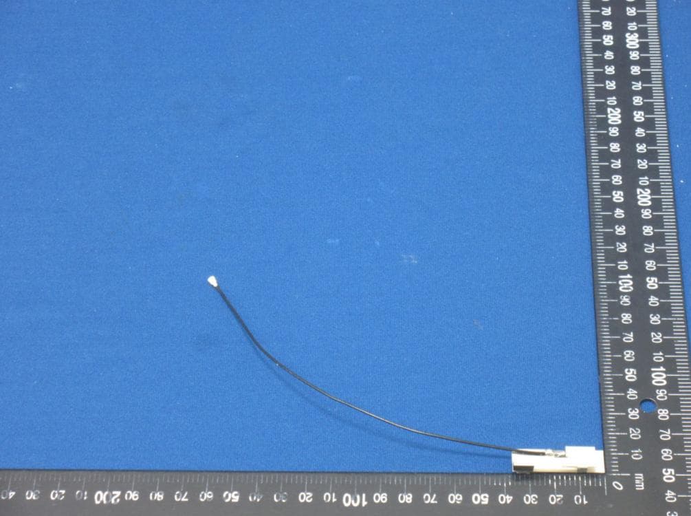
FCC ID: 2AJVQ-MT7601UB External Photos FCC ID: 2AJVQ-MT7601UB
ID Label/Location Info
FCC ID: 2AJVQ-MT7601UB The 2AJVQ is “grantee code”; “MT7601UB” is product code (Max. 14). The “FCC ID: 2AJVQ-MT7601UB” is about to print on the top layer of the module.
Internal Photos
FCC ID: 2AJVQ-MT7601UB Internal Photos FCC ID: 2AJVQ-MT7601UB
RF Exposure Info
Qingdao Intelligent&Precise Electronics Co., Ltd MPE ASSESSMENT REPORT Report Type: FCC Part §2.1091, §2.1093 and §1.1307(b) assessment report Model: ZDGFMT7601U-B REPORT NUMBER: 200401438SHA-002 ISSUE DATE: May 18, 2020 DOCUMENT CONTROL NUMBER: TTRFFCCMPE-01_V1 © 2018 Intertek Intertek Testing Services Shanghai Building No.86, 1198 Qinzhou Road (North) Caohejing Development Zone Shanghai 200233, China Telephone: 86 21 6127 8200 www.intertek.com TEST REPORT This report is for the exclusive use of Intertek's Client and is provided pursuant to the agreement between Intertek and its Client. Intertek's responsibility and liability are limited to the terms and conditions of the agreement. Intertek assumes no liability to any party, other than to the Client in accordance with the agreement, for any loss, expense or damage occasioned by the use of this report. Only the Client is authorized to permit copying or distribution of this report and then only in its entirety. Any use of the Intertek name or one of its marks for the sale or advertisement of the tested material, product or service must first be approved in writing by Intertek. The observations and test results in this report are relevant only to the sample tested. This report by itself does not imply that the material, product, or service is or has ever been under an Intertek certification program. TTRFFCCMPE-01_V1© 2018 Intertek Page 2 of 8 Report no.: 200401438SHA-002 Applicant: Qingdao Intelligent&Precise Electronics Co., Ltd No.218, Qianwangang Road, Qingdao Economic&Technological Development Zone, Shandong, China. Manufacturer: Qingdao Intelligent&Precise Electronics Co., Ltd No.218, Qianwangang Road, Qingdao Economic&Technological Development Zone, Shandong, China. Manufacturing site: Qingdao Intelligent&Precise Electronics Co., Ltd No.218, Qianwangang Road, Qingdao Economic&Technological Development Zone, Shandong, China. FCC ID: 2AJVQ-MT7601UB SUMMARY: The equipment complies with the requirements according to the following standard(s) or Specification: KDB447498 D01 General RF Exposure Guidance v06 FCC Part2.1091, FCC Part2.1093 FCC Part1.1307(b) PREPARED BY: REVIEWED BY: Project Engineer Nemo Li Reviewer Daniel Zhao Report No.: 200401438SHA-002 TEST REPORT TTRFFCCMPE-01_V1© 2018 Intertek Page 3 of 8 Revision History Report No. Version Description Issued Date 200401438SHA-002 Rev. 01 Initial issue of report May 18, 2020 Report No.: 200401438SHA-002 TEST REPORT TTRFFCCMPE-01_V1© 2018 Intertek Page 4 of 8 1 GENERAL INFORMATION 1.1 Description of Equipment Under Test (EUT) Product name: WLAN module Type/Model: ZDGFMT7601U-B Description of EUT: EUT is a WLAN Module with WiFi function, and has only one model. Rating: DC 3.3V EUT type: Table top Floor standing Software Version: / Hardware Version: / Sample received date: April 15, 2020 Date of test: April 15, 2020 ~ May 15, 2020 1.2 Technical Specification Frequency Band: 2400MHz ~ 2483.5MHz Support Standards: IEEE 802.11b, IEEE 802.11g, IEEE 802.11n(HT20), IEEE 802.11n(HT40) Operating Frequency: 2412MHz to 2462MHz for IEEE 802.11b/g/n(HT20) 2422MHz to 2452MHz for IEEE 802.11n(HT40) Type of Modulation: IEEE 802.11b: DSSS (CCK, DQPSK, DBPSK) IEEE 802.11g: OFDM (64-QAM, 16-QAM, QPSK, BPSK) IEEE 802.11n(HT20): OFDM (64-QAM, 16-QAM, QPSK, BPSK) IEEE 802.11n(HT40): OFDM (64-QAM, 16-QAM, QPSK, BPSK) Channel Number: 11 Channels for 802.11b, 802.11g and 802.11n(HT20) 9 Channels for 802.11n(HT40) Channel Separation: 5 MHz Antenna Information: PCB Antenna, 1.02dBi Report No.: 200401438SHA-002 TEST REPORT TTRFFCCMPE-01_V1© 2018 Intertek Page 5 of 8 1.3 Description of Test Facility Name: Intertek Testing Services Shanghai Address: Building 86, No. 1198 Qinzhou Road(North), Shanghai 200233, P.R. China Telephone: 86 21 61278200 Telefax: 86 21 54262353 The test facility is recognized, certified, or accredited by these organizations: CNAS Accreditation Lab Registration No. CNAS L0139 FCC Accredited Lab Designation Number: CN1175 IC Registration Lab CAB identifier.: CN0051 VCCI Registration Lab Registration No.: R-14243, G-10845, C-14723, T-12252 A2LA Accreditation Lab Certificate Number: 3309.02 Report No.: 200401438SHA-002 TEST REPORT TTRFFCCMPE-01_V1© 2018 Intertek Page 6 of 8 2 MPE Assessment Test result: Pass 2.1 MPE Assessment Limit Mobile device exposure for standalone operations: Frequency range E-field strength (V/m) H-field strength (A/m) B-field (uT) Equivalent plane wave power density S eq (W/m 2 ) 0-1 Hz - 3,2 × 10 4 4 × 10 4 - 1-8 Hz 10 000 3,2 × 10 4 /f 2 4 × 10 4 /f 2 - 8-25 Hz 10 000 4 000/f 5 000/f - 0,025-0,8 kHz 250/f 4/f 5/f - 0,8-3 kHz 250/f 5 6,25 - 3-150 kHz 87 5 6,25 - 0,15-1 MHz 87 0,73/f 0,92/f - 1-10 MHz 87/f 1/2 0,73/f 0,92/f - 10-400 MHz 28 0,073 0,092 2 400-2 000 MHz 1,375 f 1/2 0,0037 f 1/2 0,0046 f 1/2 f/200 2-300 GHz 61 0,16 0,20 10 Mobile device exposure for simultaneous transmission operations: the sum of the MPE ratios for all simultaneously transmitting antennas incorporated in a host device is ≤ 1.0 Report No.: 200401438SHA-002 TEST REPORT TTRFFCCMPE-01_V1© 2018 Intertek Page 7 of 8 2.2 Assessment Results Power density (S) is calculated according to the formula: S = PG / (4πR²) Where S = power density in mW/cm² P = Radiated transmit power in mW G = numeric gain of transmit antenna R = distance (cm) As we can see from the test report 191102802SHA-001: The calculations in the table below use the highest gain of antenna for client EUT. These calculations represent worst case in terms of the exposure levels. Mode Frequency band Max Power Antenna Gain R S Limits (MHz) dBm dBi (cm) (mW/cm2) (mW/cm2) WiFi 2400 -2483.5 17.63 1.02 20 0.0146 1 Note: 1 mW/cm2 from 1.310 Table 1 Report No.: 200401438SHA-002 TEST REPORT TTRFFCCMPE-01_V1© 2018 Intertek Page 8 of 8 Appendix I Definition below must be outlined in the User Manual: To satisfy FCC RF exposure requirements, a separation distance of 20 cm or more should be maintained between the antenna of this device and persons duri…
Text truncated - open the document above for the full version.
Test Report
Qingdao Intelligent&Precise Electronics Co., Ltd RF TEST REPORT Report Type: FCC Part 15.247 & ISED RSS-247 RF report Model: ZDGFMT7601U-B REPORT NUMBER: 200401438SHA-001 ISSUE DATE: May 18, 2020 DOCUMENT CONTROL NUMBER: TTRF15.247-03_V1 © 2018 Intertek Intertek Testing Services Shanghai Building No.86, 1198 Qinzhou Road (North) Caohejing Development Zone Shanghai 200233, China Telephone: 86 21 6127 8200 www.intertek.com TEST REPORT This report is for the exclusive use of Intertek's Client and is provided pursuant to the agreement between Intertek and its Client. Intertek's responsibility and liability are limited to the terms and conditions of the agreement. Intertek assumes no liability to any party, other than to the Client in accordance with the agreement, for any loss, expense or damage occasioned by the use of this report. Only the Client is authorized to permit copying or distribution of this report and then only in its entirety. Any use of the Intertek name or one of its marks for the sale or advertisement of the tested material, product or service must first be approved in writing by Intertek. The observations and test results in this report are relevant only to the sample tested. This report by itself does not imply that the material, product, or service is or has ever been under an Intertek certification program. TTRF15.247-03_V1 © 2018 Intertek Page 2 of 64 Report no.: 200401438SHA-001 Applicant: Qingdao Intelligent&Precise Electronics Co., Ltd No.218, Qianwangang Road, Qingdao Economic&Technological Development Zone, Shandong, China. Manufacturer: Qingdao Intelligent&Precise Electronics Co., Ltd No.218, Qianwangang Road, Qingdao Economic&Technological Development Zone, Shandong, China. Factory: Qingdao Intelligent&Precise Electronics Co., Ltd No.218, Qianwangang Road, Qingdao Economic&Technological Development Zone, Shandong, China. FCC ID: 2AJVQ-MT7601UB SUMMARY: The equipment complies with the requirements according to the following standard(s) or Specification: 47CFR Part 15 (2019): Radio Frequency Devices (Subpart C) ANSI C63.10 (2013): American National Standard of Procedures for Compliance Testing of Unlicensed Wireless Devices RSS -247 Issue 2 (February 2017): Digital Transmission Systems (DTSs), Frequency Hopping Systems (FHSs) and Licence-Exempt Local Area Network (LE-LAN) Devices RSS -Gen Issue 5 (March 2019) Amendment 1: General Requirements for Compliance of Radio Apparatus PREPARED BY: REVIEWED BY: Project Engineer Nemo Li Reviewer Daniel Zhao Report No.: 200401438SHA-001 TEST REPORT TTRF15.247-03_V1 © 2018 Intertek Page 3 of 64 Content REVISION HISTORY................................................................................................................................................ 5 MEASUREMENT RESULT SUMMARY ..................................................................................................................... 6 1 GENERAL INFORMATION ............................................................................................................................. 7 1.1 DESCRIPTION OF EQUIPMENT UNDER TEST (EUT) ..................................................................................................... 7 1.2 TECHNICAL SPECIFICATION .................................................................................................................................... 7 1.3 ANTENNA INFORMATION....................................................................................................................................... 8 1.4 DESCRIPTION OF TEST FACILITY .............................................................................................................................. 9 2 TEST SPECIFICATIONS ................................................................................................................................. 10 2.1 STANDARDS OR SPECIFICATION ............................................................................................................................. 10 2.2 MODE OF OPERATION DURING THE TEST ................................................................................................................. 10 2.3 TEST SOFTWARE LIST .......................................................................................................................................... 11 2.4 TEST PERIPHERALS LIST ....................................................................................................................................... 11 2.5 TEST ENVIRONMENT CONDITION: .......................................................................................................................... 11 2.6 INSTRUMENT LIST .............................................................................................................................................. 12 2.7 MEASUREMENT UNCERTAINTY ............................................................................................................................. 14 3 MINIMUM 6DB BANDWIDTH ..................................................................................................................... 15 3.1 LIMIT .............................................................................................................................................................. 15 3.2 MEASUREMENT PROCEDURE ............................................................................................................................... 15 3.3 TEST CONFIGURATION ........................................................................................................................................ 15 3.4 TEST RESULTS OF MINIMUM 6DB BANDWIDTH ....................................................................................................... 15 4 MAXIMUM CONDUCTED OUTPUT POWER AND E.I.R.P. ............................................................................. 16 4.1 LIMIT ...........................................................................................…
Text truncated - open the document above for the full version.
Test Report
Report No.: 200401438SHA-001 TEST REPORT TTRF15.247-03_V1 © 2018 Intertek Page 45 of 64 802.11b,2412MHz,Ant0 802.11b,2437MHz,Ant0 802.11b,2462MHz,Ant0 802.11g,2412MHz,Ant0 802.11g,2437MHz,Ant0 802.11g,2462MHz,Ant0 802.11n(HT20),2412MHz,Ant0 802.11n(HT20),2437MHz,Ant0 Report No.: 200401438SHA-001 TEST REPORT TTRF15.247-03_V1 © 2018 Intertek Page 46 of 64 802.11n(HT20),2462MHz,Ant0 802.11n(HT40),2422MHz,Ant0 802…
Text truncated - open the document above for the full version.
Contact Information
Applicant
Haining Wang(Certification Engineer)
Technical Contact
Intertek Testing Services Limited ShanghaiNemo Li
[email protected]86 21 61278265
Building No.86, 1198 Qinzhou Road(North) · Shanghai · China
Test Firm
Intertek Testing Services ShanghaiLeah Xu
[email protected]+86 21 61278200
Technical Specifications
| # | Rule Parts | Frequency Range | Power Output |
|---|---|---|---|
| 1 | 15C | 2.41 GHz - 2.46 GHz | 58.00 mW |
Other Applications from Qingdao Intelligent&Precise Electronics Co.,Ltd
2AJVQ-WM55US01
Aug 28, 2026WiFi/BT Module
Equipment Class
DSS - Part 15 Spread Spectrum Transmitter2AJVQ-WM55UP01
Aug 07, 2026WiFi/BT Module
Equipment Class
DTS - Digital Transmission System2AJVQ-MWH568S
Mar 09, 2026WiFi/BT Module
Equipment Class
DSS - Part 15 Spread Spectrum Transmitter2AJVQ-MWH567B
Mar 06, 2026WiFi/BT Module
Equipment Class
DSS - Part 15 Spread Spectrum Transmitter2AJVQ-MWH653S
Feb 09, 2026WiFi/BT Module
Equipment Class
DTS - Digital Transmission System