2AJYS-JOYLITETWS Bluetooth Headset
Happy Plugs AB
Click to zoom
Application Details
- Equipment Class
- DSS - Part 15 Spread Spectrum Transmitter
- Date of Grant
- Jul 30, 2023
- Application Purpose
- Original Equipment
- Date of Application
- Jul 30, 2023
- Equipment Note
- TWS Bluetooth Headset
- Frequency Range
- 2402.00000000 - 2480.00000000
- Company
- Happy Plugs AB
- Country
- Sweden
Documents & Files
Document Text
Text extracted from the exhibit documents filed with the FCC. Open a document above to read the original.
Users Manual
ENGLISH 1 FRANÇAIS 2 DEUTSCH 3 ESPAÑOL 4 PORTUGUÊS 5 ITALIANO 6 NEDERLANDS 7 ČESKÝ 8 正體中文 9 简体中文 10 日本語 11 한국어 12 THANK YOU Thank you for choosing our vibrant true wireless headphones! We’re grateful to have customers like you who appreciate spreading joy, happiness, and colors into the world. Your support means everything to us as we strive to deliver exceptional audio experiences wrapped in a rainbow of shades. It’s our pleasure to be a part of your musical journey, enhancing every beat with vividness. Here’s to more colorful moments together! Happy Plugs Team USER MANUAL HAPPY PLUGS JOY LITE 12 CONNECT AND USE Charge your JOY LITE for a least 10 minutes before use. Open the charge case and keep the earbuds in place to enter pairing mode. Select “Happy Plugs Joy Lite” on your phone/device to pair. Your earbuds are now ready to use. RESET TO FACTORY SETTINGS Delete “Happy Plugs Joy Lite” from your Bluetooth devices list. Make sure the charge case is charged. Put the earbuds in the charge case. With the lid of the charge case open, press and hold the button on the bottom of the charge case for 6 seconds until LED flash 7 times. The earbuds are now reset and ready to pair to your device. Just follow the “Connect and use” steps. CALLS When using the JOY LITE for phone calls, both earbuds are active. If you wish to use only one earbud during a phone call, please put the other earbud into the charge case and close the lid. CONNECTION ET UTILISATION Chargez vos écouteurs JOY LITE pendant 10 minutes minimum avant utilisation. Ouvrez le boîtier de charge et laissez les écouteurs à l’intérieur pour entrer en mode appairage. Sélectionnez “Happy Plugs Joy Lite” sur votre appareil. Vos écouteurs sont prêts à être utilisés. RETABLIR LA CONFIGURATION D’USINE Supprimez “Happy Plugs Joy Lite” de votre liste d’appareils connectés en Bluetooth. Assurez vous que le boîtier soir complètement chargé. Placez vos écouteurs à l’intérieur du boîtier de charge. Gardez le boîtier de charge ouvert, maintenez le bouton à la base du boîtier enfoncé pendant 6 secondes jusqu’à ce que le voyant LED clignote 7 fois. Les écouteurs sont maintenant réinitialisés et prêts pour un nouvel appairage. Suivez les étapes “connection et utilisation”. APPELS Lorsque vous utilisez JOY LITE pour vos appels téléphoniques, les deux écouteurs sont actifs. Si vous ne souhaitez utiliser qu’un seul écouteur, placez le second dans le boîtier de charge et fermez le couvercle. TOUCH CONTROLS × 1 Play / Pause × 2 Nex t Track × 3 Previous Track × 1 Call Answer / Call End × 2 Reject Call 2 s Accept Call and End First Call 2 s Siri / Google Assistant × 1 Volume Up × 2 Volume Down CHARGE CASE BUTTON × 1 Battery Status 6 s Reset Earphones BATTERY LIGHT 0 - 20 % Red 20 - 80 % Blue 80 - 100% Green Full instructions & FAQ available at: help.happyplugs.com COMMANDES TACTILES × 1 Marche / Arrêt × 2 Piste suivante × 3 Piste précédente × 1 Prendre un appel / Mettre fin à un appel × 2 Rejeter un appel 2 s Prendre un appel et terminer le premier appel 2 s Siri / Google Assistant × 1 Augmenter le volume × 2 Baisser le volume BOITIER DE CHARGE × 1 État de la batterie 6 s Réinitialisation des écouteurs VOYANT DE BATTERIE 0 - 20 % Rouge 20 - 80 % Bleu 80 - 100% Vert Manuel d’utilisation complet & FAQ disponibles sur: help.happyplugs.com ENGLISH 1 2 3 1 2 6 sec 10 min HAPPY PLUGS JOY LITE FRANÇAIS 11 1 1 2 2 3 3 3 3 2 2 R R ! ! LL 34 DEUTSCHESPAÑOL ANSCHLUSS UND VERWENDUNG Laden Sie Ihren JOY LITE vor dem Gebrauch mindestens 10 Minuten lang auf. Öffnen Sie den Lade-Etui und lassen Sie die Ohrhörer in dem Etui, um in den Pairing-Modus zu wechseln. Wählen Sie “Happy Plugs Joy Lite” auf Ihrem Handy / Gerät zum Koppeln. Ihre Kopfhörer sind jetzt einsatzbereit. ZURÜCKSETZEN DER FABRIK-EINSTELLUNGEN Löschen Sie “Happy Plugs Joy Lite” aus Ihrer Bluetooth- Geräteliste. Stellen Sie sicher, dass der Lade-Etui aufgeladen ist. Legen Sie die Kopfhörer in den Lade-Etui. Halten Sie bei geöffnetem Deckel des Lade-Etui die Taste an der Unterseite des Lade-Etuis 6 Sekunden lang gedrückt, bis LED 7 Mal blinken. Die Kopfhörer sind jetzt zurückgesetzt auf Fabrik-Modus und können mit Ihrem Gerät gekoppelt werden. Befolgen Sie einfach die Schritte “Anschluss und verwendung”. ANRUFE Wenn Sie den JOY LITE für Telefonanrufe verwenden, sind beide Ohrhörer aktiv. Wenn Sie während eines Telefongesprächs nur einen Kopfhörer verwenden möchten, legen Sie den anderen Kopfhörer in den Lade-Etui und schließen Sie den Deckel. CONEXIÓN Y UTILIZACIÓN Carga tus JOY LITE al menos durante 10 minutos antes de usarlos. Abre el estuche de carga y manten los auriculares dentro para empezar el emparejamiento. Selecciona “Happy Plugs Joy Lite” en tu dispositivo para el emparejamiento. Tus auriculares están listos para su uso. RESTABLECER AJUSTES DE FÁBRICA Borra “Happy Plugs Joy Lite” de tu lista de dispositivos del Bluetooth. Asegúrate de que el estuche de carga está cargado. Introduce los auriculares en el estuche de carga. Con el estuche de carga abierto, presiona el botón situado en la parte inferior durante 6 segundos hasta que el LED parpadeen 7 veces. Los auriculares están ahora reiniciar y listos para emparejar de nuevo con tu dispositivo. Sigue las indicaciones del apartado “Conexión y utilización”. LLAMADAS Cuando estás utilizando los JOY LITE ambos auriculares están activos. Si deseas solo utilizar un auricular durante una llamada, coloca el otro en el estuche de carga y cierra la tapa. TOUCH-STEUERUNG × 1 Play / Pause × 2 Nächster Titel × 3 Vorheriges Lied × 1 Anruf annehmen / Anruf beenden × 2 Anruf ablehnen 2 s Anruf annehmen und erstgespräch beenden 2 s Siri / Google Assistant × 1 Lautstärke erhöhen × 2 Lautstärke runter L ADEBOX TASTE × 1 Batteriestatus 6 s Kopfhörer zurücksetzen im Fabrik Modus BATTERIELEUCHTE 0 - 20 % Rot 20 - 80 % Blau 80 - 100% Grün Vollständige Anweisungen und häufig gestellte Fragen finden Sie unter: help.happyplugs.com CONTROLES TÁCTILES × 1 Play / Pause × 2 Siguiente …
Text truncated - open the document above for the full version.
Attestation Statements
Happy Plugs AB Energigatan 15B, 434 37 Kungsbacka, Sweden Federal Communications Commission Authorization and Evaluation Division 7435 Oakland Mills Road Columbia, MD 21046 USA Date: Jul. 14, 2023 Ref: Attestation Statements Part 2.911(d)(5)(ii) Filing FCC ID: 2AJYS-JOYSLITE Product Name: TWS Bluetooth Headset Model Name: Happy Plugs Joy Lite [Happy Plugs AB] (“the applicant”) certifies that the equipment for which authorization is sought is not “covered” equipment prohibited from receiving an equipment authorization pursuant to section 2.903 of the FCC rules. Sincerely, (Applicant signature) Name: Joe Wong Title: Sourcing and R&D Manager
Attestation Statements
Happy Plugs AB Energigatan 15B, 434 37 Kungsbacka, Sweden Federal Communications Commission Authorization and Evaluation Division 7435 Oakland Mills Road Columbia, MD 21046 USA Date: Jul. 14, 2023 Ref: Attestation Statements Part 2.911(d)(5)(ii) Filing FCC ID: 2AJYS-JOYSLITE Product Name: TWS Bluetooth Headset Model Name: Happy Plugs Joy Lite [Happy Plugs AB] (“the applicant”) certifies that, as of the date of the filing of the application, the applicant is not identified on the Covered List as an entity producing “covered” equipment. Sincerely, (Applicant signature) Name: Joe Wong Title: Sourcing and R&D Manager
Attestation Statements
2.911 (d)(7)USA A gent v1.2 Section 2. 91 1( d)(7) USA Agent for Ser vi ce of Process Company name: Happy Plugs AB Address: Energigatan 15 B, 434 37 Kungsbacka, Sweden Product Name: TWS Bl uetooth Headset FCC ID: 2 AJYS-J OYLI TE Model(s ): Happy Plugs Joy Lite 2. 91 1(d)(7) USA Designated Agent fo r Servi ce of Pr ocess We, [Happy Plugs AB] (“t he applicant”) designate [Wilson Tech Service LLC] NOTE1 for the purpose of accepting ser vice of process on behalf of the applicant. Applicant consent: We Acknowled ge our con sent to ac cep t service of process in the United St at es for matters rel at ed to t he applicable equipment, and at the physical U. S. address an d email address of the design at ed agent and acknowledge our acceptance of our obligation to mai ntai n an agent for service of process in the United St at es for no less than one year af ter either the grantee has permanently terminated all marketing and import ation of the applicable equipment within the U. S., or the conclus ion of any Commission-related admini strative or judicial proceeding inv olving the equipment, whichever i s lat er. Agent obligation: We Acknowledge our obligation to ac cept service o f pr oc ess in the United St at es for matters rel at ed to the applicable equipment at our physical U. S. address an d email address for no les s than one year af ter either the grantee has permanently terminated all market ing and importation of the applicable equipment within the U. S., or the conclus ion of any Commission-relat ed admini strative or judicial proceeding inv ol ving the equipment, whichever is lat er. USA Agent Company name: Wilson Tech Service LLC Address: 1312 17th Street Suite 692, Denver, CO, 80202, USA FRN 0033402033 Contac t Name: Wilson Cheung Tel ephone No: +1-716-965-5112 Email: Wilson.Cheung.FDA@gmail. com Applicant Company name: Happy Plugs AB Address: Energigatan 15 B, 434 37 Kungsbacka, Sweden Contac t Name: Joe Wong Tel ephone No: +852 95127941 Email: joe@happypl ugs.com 2.911 (d)(7)USA A gent v1.2 Si gnature: Title: +1-716-965-5112 Si gnature: Title: Sourcing and R&D manager Date: Jul y-4 th, 2023 Date: Jul y-4 th, 2023 NOTE 1: An applicant lo cated in the Uni ted States may de sig nate it self as the agent for ser vice of pr ocess. Refere nce ; Federal Regist er document 2022-2 8263 publis hed on 02/06/23 https://www.federalr egister.gov/do cument s/2023/ 02/06/ 2022-28 26 3/ pr ot ecting-against- national-sec urit y-threats-to-the-communicat ions-supply-chain-throu gh-the
Cover Letter(s)
Happy Plugs AB Energigatan 15B, 434 37 Kungsbacka, Sweden Agent Authorization Company: Happy Plugs AB Address: Energigatan 15B, 434 37 Kungsbacka, Sweden Product Name: TWS Bluetooth Headset Model Number(s): Happy Plugs Joy Lite Product Description: TWS Bluetooth Headset We authorize MiCOM Labs Inc., 575 Boulder Court, Pleasanton, California 94566, USA, to act on our behalf on all matters concerning the certification of above named equipment. We declare that MiCOM Labs Inc. is allowed to forward all information related to the approval and certification of equipment to the regulatory agencies as required and to discuss any issues concerning the approval application. Any and all acts carried out by MiCOM Labs on our behalf shall have the same effect as acts of our own. Signature: Date: Jul. 14, 2023 Name: Joe Wong Title: Sourcing and R&D Manager Company: Happy Plugs AB
Cover Letter(s)
Happy Plugs AB Energigatan 15B, 434 37 Kungsbacka, Sweden Office of Engineering Technology Federal Communications Commission 7435 Oakland Mills Road Columbia, MD 21046 USA Date: Jul. 14, 2023 Subject; Request for Confidentiality FCC ID: 2AJYS-JOYLITE To Whom It May Concern, Pursuant to the provisions of the Commission’s rules Title 47 Sections §0.457 and §0.459, we are requesting the Commission to withhold the following attachment(s) as confidential documents from public disclosure indefinitely. These documents contain detailed system and equipment descriptions and are considered as proprietary information in operation of the equipment. The public disclosure of these documents might be harmful to our company and would give competitors an unfair advantage in the market. Schematic Diagram Block Diagram Operational Description In additional to above mentioned documents, in order to comply with the marketing regulations in Title 47 CFR §2.803 and the importation rules in Title 47 CFR §2.1204, while ensuring that business sensitive information remains confidential until the actual marketing of newly authorized devices, we request Short Term Confidentiality of the following attachment(s); External Photos Test Setup Photos Internal Photos User Manual For 45 days, pursuant to Public Notice DA 04-1705. OR For 180 days pursuant to KDB 726920 D01. It is our understanding that all measurement test reports, FCC ID label format and correspondence during the certification review process cannot be granted as confidential documents and this information will be available for public review once the grant of equipment authorization is issued. Sincerely, Signature: Name: Joe Wong Title: Sourcing and R&D Manager
External Photos
Report No.: AGC01082230604AP02 Page 1 of 4 EXTERNAL PHOTOS WHOLE VIEW OF EUT TOP VIEW OF EUT Report No.: AGC01082230604AP02 Page 2 of 4 BOTTOM VIEW OF EUT FRONT VIEW OF EUT Report No.: AGC01082230604AP02 Page 3 of 4 BACK VIEW OF EUT LEFT VIEW OF EUT Report No.: AGC01082230604AP02 Page 4 of 4 RIGHT VIEW OF EUT ****************************************End of Report*************************************
ID Label/Location Info
FCC ID and IC Label Location The product does not have enough space to place the label, and FCC ID label is reflected in the user manual and package, as below:
Internal Photos
Report No.: AGC01082230604AP02 Page 1 of 3 INTERNAL PHOTOS OPEN VIEW OF EUT VIEW OF BATTERY Report No.: AGC01082230604AP02 Page 2 of 3 INTERNAL VIEW OF EUT-1 INTERNAL VIEW OF EUT-2 Report No.: AGC01082230604AP02 Page 3 of 3 INTERNAL VIEW OF EUT-3 ****************************************End of Report************************************* BT Antenna BT Antenna
RF Exposure Info
RF EXPOSURE EVALUATION 1. PRODUCT INFORMATION FCC ID 2AJYS-JOYLITE Product Description TWS Bluetooth Headset Model Name Happy Plugs Joy Lite Frequency Band (Operating) WLAN: 2.412GHz ~ 2.462GHz WLAN: 5.18GHz ~ 5.32GHz / 5.50GHz ~ 5.70GHz WLAN: 5.745GHz ~ 5825GHz Bluetooth: 2.402GHz ~ 2.480GHz Others (NFC:13.56MHz) Device Category Portable (<20cm separation) Mobile (>20cm separation) Others: Antenna Diversity Single antenna Multiple antennas Max. Output Power -1.079dBm (Max) Antenna Gain 3.4dBi Minimum Assessment Distance 5mm Evaluation Applied MPE Evaluation SAR Evaluation Evaluation Result Pass 2. PORTABLE DEVICE EVALUATION METHOD AND LIMIT Following FCC KDB 447498 D01 “General SAR test exclusion guidance” The corresponding SAR Exclusion Threshold condition, listed below: 1) The 1-g and 10-g SAR test exclusion thresholds for 100 MHz to 6 GHz at test separation distances ≤50 mm are determined by: [(max. power of channel, including tune-up tolerance, mW)/(min. test separation distance, mm)] [if(GHz)] s 3.0 for 1-g SAR and ñ 7.5 for 10-g extremity SAR, where f(GHz) is the RF channel transmit frequency in GHz. Power and distance are rounded to the nearest mW and mm before calculation. The result is rounded to one decimal place for comparison The test exclusions are applicable only when the minimum test separation distance is ≤50 mm and for transmission frequencies between 100 MHz and 6 GHz. When the minimum test separation distance is < 5 mm, a distance of 5 mm is applied to determine SAR test exclusion. 2) At 100 MHz to 6 GHz and for test separation distances > 50 mm, the SAR test exclusion threshold is determined according to the following: a) [Threshold at 50 mm in step 1) + (test separation distance - 50mm) ( f(MHz)/150)] mW, at 100MHz to 1500 MHz; b) [Threshold at 50 mm in step 1) + (test separation distance - 50 mm)-10] mW at > 1500 MHz and ≤6 GHz; 3) At frequencies below 100 MHz, the following may be considered for SAR test exclusion. a) The threshold at the corresponding test separation distance at 100 MHz in step 2) is multiplied by [1 + log(100/f(MHz))] for test separation distances > 50 mm and < 200 mm. b) The threshold determined by the equation in a) for 50 mm and 100 MHz is multiplied by 1/2 for test separation distances ñ 50 mm. c) SAR measurement procedures are not established below 100 MHz. When SAR test exclusion cannot be applied, a KDB inquiry is required to determine SAR evaluation requirements for any test results to be acceptable. 3. MOBILE DEVICE EVALUATION METHOD AND LIMIT Human exposure to RF emissions from mobile devices (47 CFR §2.1091) may be evaluated based on the MPE limits adopted by the FCC for electric and magnetic field strength and/or power density, as appropriate, since exposures are assumed to occur at distances of 20 cm or more from persons. LIMITS FOR GENERAL POPULATION / UNCONTROLLED EXPOSURE Frequency Range (MHz) E-field Strength (E) (V/m) Magnetic Field Strength (H) (A/m) Power Density (S) (mW/cm 2 ) Averaging Time |E| 2 , |H| 2 or S (Minutes) 0.3 -- 1.34 614 1.63 (100)* 30 1.34 -- 30 824/f 2.19/f (180/f 2 )* 30 30 -- 300 27.5 0.073 0.2 30 300 -- 1500 -- -- f/1500 30 1500 -- 100,000 -- -- 1.0 30 *Note: 1. f= Frequency in MHz * Plane-wave Equivalent Power Density 2. The averaging time for General Population/Uncontrolled exposure to fixed transmitters is not applicable for mobile and portable transmitters. See 47 CFR §§2.1091 and 2.1093 on source-based time-averaging requirement for mobile and portable transmitters. S=PG/4πR² Where: S=power density P=power input to antenna G=power gain of the antenna in the direction of interest relative to an isotropic radiator R=distance to the center of radiation of the antenna 4. MEASUREMENT RESULT Test Mode Channel Frequency (MHz) Max Output power (dBm) Max Output power (mW) Calculati on Value (Note 1) Threshold Value π/4-DQPSK BT_EDR 2441 -1.079 0.78 0.243 3.0 Note 1: Calculation Value =[(max. power of channel, mW)/(min. test separation distance, mm)] ·[√f(GHz)]. Fox example: 0.78/5*√2.441=0.243 ≤ 3.0 According to KDB447498 D01 V06, threshold at which no SAR required is ≤3.0 for 1-g SAR, separation distance is 5mm, and no simultaneous SAR measurement is required. 5. CONCLUSION Since Source-base time average power is below SAR test exclusion power thresholds, the SAR evaluation is not required.
Test Report
SymbolsLWTA Dimensions1.60±0.200.80±0.200.80±0.200.30±0.10 NumberTerminal Name ① INPUT ② NC Dimensions(Unit:mm) L w ①② T ( Side View ) ( Bottom View ) ( Top View ) A Features 1.Surface Mounted Devices with a small dimension of 1.6 x 0.8 x 0.8 mm meet future miniaturization trend. 2,Embedded and LTCC (low temperature co-fired ceramic) technology is able to integrate with system design as well as beatifying the housing of final product. 3.High stability and low tolerance. Applications 1. Bluetooth 2. Wireless LAN 3. ISM band 2.4GHz wireless applications www.surbaner.com.cn SBR Communication has possession of proprietary information provided in this report and this proprietary information shall be kept in strict confidence and not disclosed to any person or firm without the prior written consent of SBR Communication Technology. . Page 1 P/N: SURL160808 SRF08 Shenzhen Shengbanger Technology Co., LTD Evaluation Board and Matching Circuits www.surbaner.com.cn SBR Communication has possession of proprietary information provided in this report and this proprietary information shall be kept in strict confidence and not disclosed to any person or firm without the prior written consent of SBR Communication Technology. . Page 2 P/N: SURL160808 SRF08 Electrical Characteristics Characteristic curve www.surbaner.com.cn SBR Communication has possession of proprietary information provided in this report and this proprietary information shall be kept in strict confidence and not disclosed to any person or firm without the prior written consent of SBR Communication Technology. . Page 3 FeatureSpecification 1 Central frequency2445MHz 2 Bandwidth>100MHz 3 Peak gain3.4dBi 4 VSWR<2 5 PolarizationLinear 6 Azimuth beamwidthOmnidirectional 7 Impedance50 Ω P/N: SURL160808 SRF08 Radiation Pattern coordinates: Y-Z Plane X-Z Plane www.surbaner.com.cn SBR Communication has possession of proprietary information provided in this report and this proprietary information shall be kept in strict confidence and not disclosed to any person or firm without the prior written consent of SBR Communication Technology. . Page 4 P/N: SURL160808 SRF08 3D Radiation Pattern www.surbaner.com.cn SBR Communication has possession of proprietary information provided in this report and this proprietary information shall be kept in strict confidence and not disclosed to any person or firm without the prior written consent of SBR Communication Technology. . Page 5 X-Y Plane Frequency 2400MHz2450MHz2500MHz Avg. gain-1.14-0.85-1.30 Peak gain23.42.5 Efficiency77%82%78% P/N: SURL160808 SRF08 Moisture Proof Temperature:40±2°C Humidity:90~95%RH Duration:500h Recovery conditions:Room temperature Recovery Time:24h (Class1) or 48h (Class2) Sol derabi li ty At least 95% of the terminal electrode is covered by new solder.Preheating conditions:80 to 120°C; 10~30s. SolderTe m p e r at u r e :2 3 5 ± 5°C Duration:2 ±0.5s , SolderTempe r atu re:24 5±5°C Du rat ion:2±0.5s Optimum Solder Amount for Reflow Soldering www.surbaner.com.cn SBR Communication has possession of proprietary information provided in this report and this proprietary information shall be kept in strict confidence and not disclosed to any person or firm without the prior written consent of SBR Communication Technology. . Page 6 Dependability Test Test Temperature: Operating Temperature Temperature Relative Humidity 25°C±3°C -25°C~+85°C 5~40°C 20~70% Too much solderCracks tend to occur due to large stress. Not enough solder Weak holding force may cause bad connection between the capacitor and PCB. Recommended Soldering amounts The optimal solder fillet amounts for re-flow soldering 天线厚度 以下 The optimal solder fillet amounts for wave soldering P/N: SURL160808 SRF08 Temperature Cycle Test 10±1S Applied Force: 5NDuration: 10±1S Preheating conditions: up-category temperature, 1h Recovery time: 24±1h Initial Measurement Cycling Times: 5 times, 1 cycle, 4 steps: www.surbaner.com.cn SBR Communication has possession of proprietary information provided in this report and this proprietary information shall be kept in strict confidence and not disclosed to any person or firm without the prior written consent of SBR Communication Technology. . Page 7 Resistanceto SolderingHeat Preheating80 to 120°C; 10~30s.SolderTemperature:235±5°C Duration:2±0.5s,SolderTemperature:245±5°C Duration:2±0.5s,Preheating100to200°C;10±2min. Solder Temperature: 265±5°C Duration: 10±1s Clean the capacitor with solvent and examine it with a 10X(min.) microscope. Recovery Time: 24±2h Recovery condition: Room temperature Resistance to Flexure of Substrate Test Board: Al 2 O 3 or PCBWarp: 1mm Speed: 0.5mm/sec. Unit: mm The measurement should be made with the board in the bending position. P/N: SURL160808 SRF08 www.surbaner.com.cn SBR Communication has possession of proprietary information provided in this report and this proprietary information shall be kept in strict confidence and not disclosed to any person or firm without the prior written consent of SBR Communication Technology. . Page 8 While in preheating,please keep the temperature difference between soldering temperature and surface temperature of chips as: T≤150°C. P/N: SURL160808 SRF08 Dimensions of paper taping for 0603types Reel(4000 pcs/Reel) Storage Period The guaranteed period for solderability is 6 months(Under deliver package condition).Temperature5~40°C /Relative Humidity20~70% www.surbaner.com.cn SBR Communication has possession of proprietary information provided in this report and this proprietary information shall be kept in strict confidence and not disclosed to any person or firm without the prior written consent of SBR Communication Technology. . Page 9 P/N: SURL160808 SRF08 Unit:mm
Test Report
Page 1 of 60 FCC Test Report Report No.: AGC01082230604FE03 FCC ID : 2AJYS-JOYLITE APPLICATION PURPOSE : Original Equipment PRODUCT DESIGNATION : TWS Bluetooth Headset BRAND NAME : Happy Plugs MODEL NAME : Happy Plugs Joy Lite APPLICANT : Happy Plugs AB DATE OF ISSUE : Jul. 11, 2023 STANDARD(S) : FCC Part 15.247 REPORT VERSION : V1.0 Attestation of Global Compliance (Shenzhen) Co., Ltd Report No.: AGC01082230604FE03 Page 2 of 60 REPORT REVISE RECORD Report Version Revise Time Issued Date Valid Version Notes V1.0 / Jul. 11, 2023 Valid Initial Release Report No.: AGC01082230604FE03 Page 3 of 60 TABLE OF CONTENTS 1. VERIFICATION OF CONFORMITY .................................................................................................................. 5 2. GENERAL INFORMATION .............................................................................................................................. 6 2.1. PRODUCT DESCRIPTION ........................................................................................................................ 6 2.2. TABLE OF CARRIER FREQUENCYS ....................................................................................................... 6 2.3. RECEIVER INPUT BANDWIDTH .............................................................................................................. 7 2.4. EXAMPLE OF A HOPPING SEQUENCY IN DATA MODE ......................................................................... 7 2.5. EQUALLY AVERAGE USE OF FREQUENCIES AND BEHAVIOUR ......................................................... 7 2.6. RELATED SUBMITTAL(S) / GRANT (S) .................................................................................................... 8 2.7. TEST METHODOLOGY ............................................................................................................................. 8 2.8. SPECIAL ACCESSORIES ......................................................................................................................... 8 2.9. EQUIPMENT MODIFICATIONS ................................................................................................................. 8 2.10. ANTENNA REQUIREMENT..................................................................................................................... 8 3. MEASUREMENT UNCERTAINTY ................................................................................................................... 9 4. DESCRIPTION OF TEST MODES ................................................................................................................. 10 5. SYSTEM TEST CONFIGURATION ................................................................................................................ 11 5.1. CONFIGURATION OF EUT SYSTEM ...................................................................................................... 11 5.2. EQUIPMENT USED IN TESTED SYSTEM .............................................................................................. 11 5.3. SUMMARY OF TEST RESULTS .............................................................................................................. 11 6. TEST FACILITY .............................................................................................................................................. 12 7. PEAK OUTPUT POWER ................................................................................................................................ 13 7.1. MEASUREMENT PROCEDURE ............................................................................................................. 13 7.2. TEST SET-UP (BLOCK DIAGRAM OF CONFIGURATION) .................................................................... 13 7.3. LIMITS AND MEASUREMENT RESULT .................................................................................................. 14 8. 20DB BANDWIDTH ........................................................................................................................................ 18 8.1. MEASUREMENT PROCEDURE ............................................................................................................. 18 8.2. TEST SET-UP (BLOCK DIAGRAM OF CONFIGURATION) .................................................................... 18 8.3. LIMITS AND MEASUREMENT RESULTS ............................................................................................... 19 9. CONDUCTED SPURIOUS EMISSION........................................................................................................... 23 9.1. MEASUREMENT PROCEDURE ............................................................................................................. 23 Report No.: AGC01082230604FE03 Page 4 of 60 9.2. TEST SET-UP (BLOCK DIAGRAM OF CONFIGURATION) .................................................................... 23 9.3. MEASUREMENT EQUIPMENT USED .................................................................................................... 23 9.4. LIMITS AND MEASUREMENT RESULT .................................................................................................. 23 10. RADIATED EMISSION ................................................................................................................................. 37 10.1. MEASUREMENT PROCEDURE ........................................................................................................... 37 10.2. TEST SETUP ......................................................................................................................................... 39 10.3. LIMITS AND MEASUREMENT RESULT ............................................................................................... 40 10.4. TEST RESULT........................................................................................................................................ 40 11. NUMBER OF HOPPING FREQUENCY ..................................................................…
Text truncated - open the document above for the full version.
Test Setup Photos
Report No.: AGC01082230604AP01 Page 1 of 2 TEST SETUP PHOTOS RADIATED EMISSION TEST SETUP BELOW 1GHz RADIATED EMISSION TEST SETUP ABOVE 1GHz Report No.: AGC01082230604AP01 Page 2 of 2 AC POWER LINE CONDUCTED TEST SETUP RF CONDUCTED TEST SETUP ****************************************End of Report*************************************
Contact Information
Applicant
Joe Wong(Sourcing and R&D Manager)
Technical Contact
Test Firm
Attestation of Global Compliance (Shenzhen) Co., LDoris Li
[email protected]+86-755-25234088
Technical Specifications
| # | Rule Parts | Frequency Range | Power Output |
|---|---|---|---|
| 1 | 15C | 2.40 GHz - 2.48 GHz | 800.00 µW |
Other Applications from Happy Plugs AB
2AJYS-PLAYLITE
Sep 11, 2024Wireless Headphone
Equipment Class
DSS - Part 15 Spread Spectrum Transmitter2AJYS-CLIP
Aug 28, 2024TWS Earphone
Equipment Class
DSS - Part 15 Spread Spectrum Transmitter2AJYS-PLAYPRO
Jul 03, 2024Wireless Headphone
Equipment Class
DSS - Part 15 Spread Spectrum Transmitter
2AJYS-JOY
Jul 14, 2022TWS Bluetooth Headset
Equipment Class
DSS - Part 15 Spread Spectrum Transmitter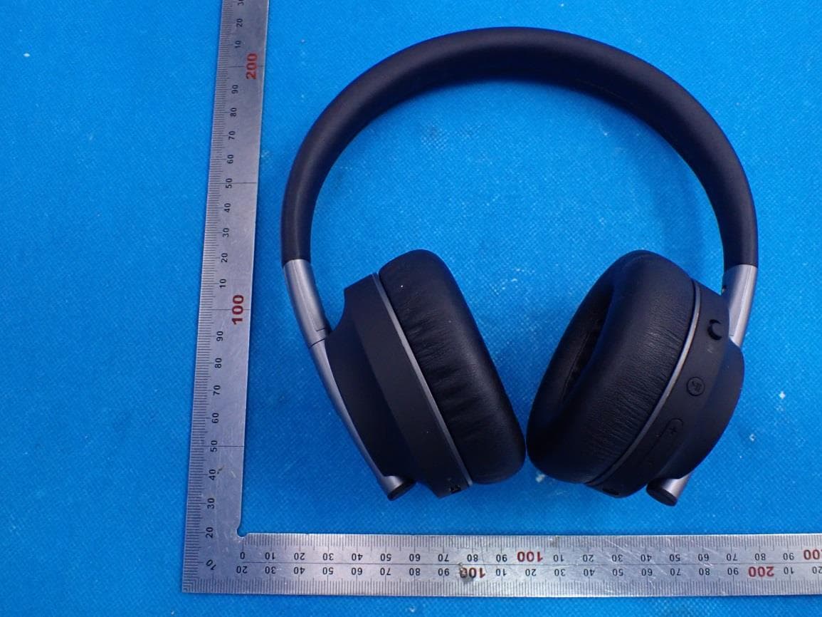
2AJYS-PLAY
Jul 29, 2021Kids Bluetooth Headphone
Equipment Class
DSS - Part 15 Spread Spectrum Transmitter