2AJYS-PLAYKids Bluetooth Headphone
Happy Plugs AB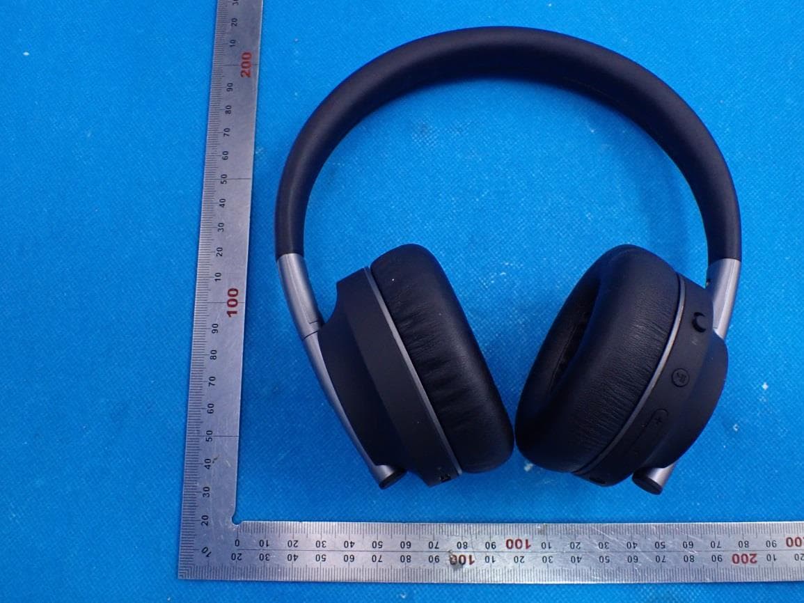
Click to zoom
Application Details
- Equipment Class
- DSS - Part 15 Spread Spectrum Transmitter
- Date of Grant
- Jul 29, 2021
- Application Purpose
- Original Equipment
- Date of Application
- Jul 29, 2021
- Equipment Note
- Kids Bluetooth Headphone
- Frequency Range
- 2402.00000000 - 2480.00000000
- Company
- Happy Plugs AB
- Country
- Sweden
Documents & Files
Document Text
Text extracted from the exhibit documents filed with the FCC. Open a document above to read the original.
Users Manual
USER MANUAL HAPPY PLUGS PL AY USER MANUAL ENGLISH 1 FRANÇAIS 3 DEUTSCH 5 ESPAÑOL 7 PORTUGUÊS 9 ITALIANO 11 NEDERLANDS13 ČESKÝ15 正體中文 17 简体中文 19 日本語 21 한국어23 THANK YOU Even before we started working on this product we thought of it as a companion piece to our previous true wireless headphones, a sequel of sorts - The next chapter. We knew it had to be special so we worked hard. And then we worked even harder. Sharing this journey with you all has been the gift of a lifetime and I hope you can see and experience our gratitude within this product. Andreas Vural, founder of Happy Plugs 3 2 4 5 6 7 18 9 10 11 1 BUTTON CONTROLS × 1 Play / Pause × 2 Nex t Track × 3 Previous Track × 1 Call Answer / Call End × 2 Reject Call × 3 Accept Call and Hold First Call 2 s Siri / Google Assistant 10 s Pairing Mode × 1 Volume Up × 1 Volume Down POWER ON / OFF Power On - Slide power button from OFF to ON Automatic Power Off - Power will automatically turn the device off if there is no connection for 10 minuted or if the battery is below 5%. CONNECT AND USE (WIRELESS) Charge your PL AY with the included Charging Cable until the green light remains on (indicating a full charge). Turn the headphones on by sliding the power button from OFF to ON. Headphones will automatically enter Pairing Mode, indicated by a green and red alternating flash. Select “Happy Plugs - Play” on your phone/device to pair. You will hear a voice prompt indicating a successfull pair. Your headphones are now ready to be used. CONNECT AND USE (WIRED) Use the included 3.5mm Cable to connect your PL AY to a device. Your PL AY does not have to be charged or turned on to be used in wired mode. The microphone doesn’t work if the headphones are used this way. PRODUCT OVERVIEW (SEE IMAGE) USB-C Charging & Audio Sharing Port Charging LED Power On / Off Multifunction Button (MFB) Volume Up / Down Bluetooth LED AUX In/Output & Audio Sharing Port Microphone Charging Cable (USB-A to USB-C) 3.5mm Cable (3.5mm to 3.5mm) USB-C Cable (USB-C to USB-C) ENGLISH 1 1 1 3 3 11 4 5 6 7 8 9 10 2 2 MFB + - ! 12 PAIR TO ADDITIONAL DEVICES With the headphones turned on, press the MFB-button for 10 seconds to enter Pairing Mode, indicated by a blue and red alternating flash. Select “Happy Plugs - Play” on your phone/device to pair. You will here a voice prompt indicating a successfull pair. Your headphones are now ready to be used. When you turn on your headphones they will automatically connect to the last connected device. AUDIO SHARING Audio Sharing can be used to connect two PL AY headphones together, listening to the same source. Connect Headphones B to Headphone A using the included the USB-C Cable. ANTIBACTERIAL PROTECTION Your PL AY comes with Biomaster antimicrobial technology, an incredibly effective way to stop the growth of harmful bacteria. The additive works 24/7 to protect product surfaces and the inbuilt antimicrobial protection is effective for the lifetime of the product with no harmful effects. Biomaster is also used in medical, food and water applications. HEARING LOSS PROTECTION Your PL AY headphones are designed to protect your eardrums from hearing damage following the World Health Organisation’s recommendation of an 85dB-limited volume range. CLEANING The leather used on this product is 100% vegan leather. Its appearance will change as you use it. It might acquire a patina and might change color due to the oils from your skin and direct sunlight, further enhancing the natural look. Cleaning the leather might affect its color. If you choose to clean it use a clean cloth with warm water and mild hand soap. Leather cleaners and conditioners can change the color of vegan leather. Full instructions & FAQ available at: help.happyplugs.com 1 1 2 ! 3 FRANÇAIS BUTTON CONTROLS × 1 Lecture / Pause × 2 Titre suivant × 3 Titre précédent × 1 Prendre un appel / Raccrocher × 2 Rejeter un appel × 3 Accepter l’appel et mettre le premier appel en attente 2 s Siri / Google Assistant 10 s Mode appairage × 1 Augmenter le volume × 1 Baisser le volume MARCHE / ARRÊT Mise en marche - positionnez le bouton de mise sous tension sur ON Arrêt automatique - les écouteurs s’éteignent automatiquement en l’absence de connexion pendant 10 minutes ou si la charge de la batterie est inférieure à 5 %. CONNEXION ET UTILISATION (SANS FIL) Chargez vos écouteurs PL AY à l’aide du câble de charge fourni jusqu’à ce que le voyant vert reste allumé (indiquant une charge complète). Mettez en marche les écouteurs en positionnant le bouton de mise sous tension sur ON. Les écouteurs passent automatiquement en mode appairage, indiqué par un clignotement alternatif vert et rouge. Sélectionnez “Happy Plugs - Play” sur votre téléphone/ appareil pour effectuer l’appairage. Un message vocal vous indique que l’appairage a réussi. Vos écouteurs sont prêts à être utilisés. CONNEXION ET UTILISATION (FILAIRE) Connectez vos écouteurs PL AY à un appareil à l’aide du câble de 3,5 mm fourni. Vos écouteurs PL AY n’ont pas besoin d’être chargés ou allumés pour être utilisés en mode filaire. Le micro ne fonctionne pas lors d’une utilisation en mode filaire. APERÇU DU PRODUIT (VOIR IMAGE) Port de charge et de partage audio USB-C Voyant LED de charge Marche / Arrêt Bouton multifonction (MFB) Volume plus / Moins Voyant LED Bluetooth Entrée/sortie auxiliaires et port de partage audio Micro Câble de chargement (USB-A vers USB-C) Câble auxiliaire 3,5 mm (3,5 mm vers 3,5 mm) Câble USB-C (USB-C vers USB-C) 1 1 1 3 3 11 4 5 6 7 8 9 10 2 2 MFB + - ! 4 APPAIRER DES APPAREILS SUPPLÉMENTAIRES Les écouteurs allumés, appuyez sur le bouton MFB pendant 10 secondes pour passer en mode appairage, indiqué par un clignotement alternatif bleu et rouge. Sélectionnez “Happy Plugs - Play” sur votre téléphone/ appareil pour effectuer l’appairage. Un message vocal vous indique que l’appairage a réussi. Vos écouteurs sont prêts à être utilisés. Lorsque vous allumez vos écouteurs, ils se connectent automatiquement au dernier appareil con…
Text truncated - open the document above for the full version.
Cover Letter(s)
Happy Plugs AB Kungsgatan 4B, 1 tr, 111 43 Stockholm, Stockholm, 11143 Sweden July 16, 2021 Federal Communication Commission Authorization and Evaluation Division FCC ID: 2AJYS-PLAY Re: Confidentiality Request Pursuant to Sections 0.457 and 0.459 of the Commission’s Rules, the applicant hereby requests confidential treatment of information applied this application as outlined below: 1: Block Diagram 2: Schematics 3: Operational Description The above materials contain trade secrets and proprietary information not customarily released to the public. The public disclosure of these matters might be harmful to the applicant and provide unjustified benefits to its competitors. The Applicant understands that pursuant to Rules 0.457, disclosure of this Application and all accompanying documentation will not be made before the date of the Grant for this application. Sincerely, Happy Plugs AB Contact person: Rickard Paulsson Title: Supply Manager
External Photos
External Photos Test Model: HAPPY PLUGS PLAY TOP VIEW OF EUT BOTTOM VIEW OF EUT FRONT VIEW OF EUT BACK VIEW OF EUT LEFT VIEW OF EUT RIGHT VIEW OF EUT VIEW OF EUT (PORT)-1 VIEW OF EUT (PORT)-2
ID Label/Location Info
Label and Label Location The Label’s material is silk-screen, it cannot be easily erased. The size for the label is 20mm*10mm The MIC Logo height is 3mm*3mm. The Printing Color is Silvery. M o d e l : H A P P Y P L U G S P L A Y I n p u t : D C 5 V 3 0 0 m A F C C I D : 2 A J Y S - P L A Y I C : 2 2 0 1 4 - P L A Y D e s i g n e d i n S w e d e n M a d e i n C h i n a K i d s B l u e t o o t h H e a d p h o n e 2 0 4 - B 0 0 4 1 9 R - R - H p P - P L A Y
Internal Photos
Internal Photos Test Model: HAPPY PLUGS PLAY OPEN VIEW OF EUT VIEW OF BATTERY INTERNAL VIEW OF EUT-1 INTERNAL VIEW OF EUT-2 INTERNAL VIEW OF EUT-3 INTERNAL VIEW OF EUT-4 INTERNAL VIEW OF EUT-5 INTERNAL VIEW OF EUT-6 Antenna INTERNAL VIEW OF EUT-7
Test Report
Page 1 of 79 FCC Test Report Report No.: AGC00213210607FE03 FCC ID : 2AJYS-PLAY APPLICATION PURPOSE : Original Equipment PRODUCT DESIGNATION : Kids Bluetooth Headphone BRAND NAME : HAPPY PLUGS MODEL NAME : HAPPY PLUGS PLAY APPLICANT : Happy Plugs AB DATE OF ISSUE : Jul. 16, 2021 STANDARD(S) : FCC Part 15.247 REPORT VERSION : V1.0 Attestation of Global Compliance (Shenzhen) Co., Ltd Report No.: AGC00213210607FE03 Page 2 of 79 REPORT REVISE RECORD Report Version Revise Time Issued Date Valid Version Notes V1.0 / Jul. 16, 2021 Valid Initial Release Report No.: AGC00213210607FE03 Page 3 of 79 TABLE OF CONTENTS 1. VERIFICATION OF CONFORMITY .................................................................................................................. 5 2. GENERAL INFORMATION .............................................................................................................................. 6 2.1. PRODUCT DESCRIPTION ........................................................................................................................ 6 2.2. TABLE OF CARRIER FREQUENCYS ....................................................................................................... 6 2.3. RECEIVER INPUT BANDWIDTH .............................................................................................................. 7 2.4. EXAMPLE OF A HOPPING SEQUENCY IN DATA MODE ......................................................................... 7 2.5. EQUALLY AVERAGE USE OF FREQUENCIES AND BEHAVIOUR ......................................................... 7 2.6. RELATED SUBMITTAL(S) / GRANT (S) .................................................................................................... 8 2.7. TEST METHODOLOGY ............................................................................................................................. 8 2.8. SPECIAL ACCESSORIES ......................................................................................................................... 8 2.9. EQUIPMENT MODIFICATIONS ................................................................................................................. 8 2.10. ANTENNA REQUIREMENT..................................................................................................................... 8 3. MEASUREMENT UNCERTAINTY ................................................................................................................... 9 4. DESCRIPTION OF TEST MODES ................................................................................................................. 10 5. SYSTEM TEST CONFIGURATION ................................................................................................................ 11 5.1. CONFIGURATION OF EUT SYSTEM ...................................................................................................... 11 5.2. EQUIPMENT USED IN TESTED SYSTEM .............................................................................................. 11 5.3. SUMMARY OF TEST RESULTS .............................................................................................................. 11 6. TEST FACILITY .............................................................................................................................................. 12 7. PEAK OUTPUT POWER ................................................................................................................................ 13 7.1. MEASUREMENT PROCEDURE ............................................................................................................. 13 7.2. TEST SET-UP (BLOCK DIAGRAM OF CONFIGURATION) .................................................................... 13 7.3. LIMITS AND MEASUREMENT RESULT .................................................................................................. 14 8. 20DB BANDWIDTH ........................................................................................................................................ 19 8.1. MEASUREMENT PROCEDURE ............................................................................................................. 19 8.2. TEST SET-UP (BLOCK DIAGRAM OF CONFIGURATION) .................................................................... 19 8.3. LIMITS AND MEASUREMENT RESULTS ............................................................................................... 20 9. CONDUCTED SPURIOUS EMISSION........................................................................................................... 25 9.1. MEASUREMENT PROCEDURE ............................................................................................................. 25 Report No.: AGC00213210607FE03 Page 4 of 79 9.2. TEST SET-UP (BLOCK DIAGRAM OF CONFIGURATION) .................................................................... 25 9.3. MEASUREMENT EQUIPMENT USED .................................................................................................... 25 9.4. LIMITS AND MEASUREMENT RESULT .................................................................................................. 25 10. RADIATED EMISSION ................................................................................................................................. 46 10.1. MEASUREMENT PROCEDURE ........................................................................................................... 46 10.2. TEST SETUP ......................................................................................................................................... 48 10.3. LIMITS AND MEASUREMENT RESULT ............................................................................................... 49 10.4. TEST RESULT........................................................................................................................................ 49 11. NUMBER OF HOPPING FREQUENCY ......................................................................…
Text truncated - open the document above for the full version.
Test Report
Report No.: AGC00213210607FE03 Page 46 of 79 10. RADIATED EMISSION 10.1. MEASUREMENT PROCEDURE 1. The EUT was placed on the top of the turntable 0.8 or 1.5 meter above ground. The phase center of the receiving antenna mounted on the top of a height-variable antenna tower was placed 3 meters far away from the turntable. 2. Power on the EUT and all the supporting units. The turntable was rotated by 360 degrees to determine the position of the highest radiation. 3. The height of the broadband receiving antenna was varied between one meter and four meters above ground to find the maximum emissions field strength of both horizontal and vertical polarization. 4. For each suspected emission, the antenna tower was scan (from 1 M to 4 M) and then the turntable was rotated (from 0 degree to 360 degrees) to find the maximum reading. 5. Set the test-receiver system to Peak or CISPR quasi-peak Detect Function with specified bandwidth under Maximum Hold Mode. 6. For emissions above 1GHz, use 1MHz RBW and 3MHz VBW for peak reading. Place the measurement antenna away from each area of the EUT determined to be a source of emissions at the specified measurement distance, while keeping the measurement antenna aimed at the source of emissions at each frequency of significant emissions, with polarization oriented for maximum response. The measurement antenna may have to be higher or lower than the EUT, depending on the radiation pattern of the emission and staying aimed at the emission source for receiving the maximum signal. The final measurement antenna elevation shall be that which maximizes the emissions. The measurement antenna elevation for maximum emissions shall be restricted to a range of heights of from 1 m to 4 m above the ground or reference ground plane. 7. When the radiated emissions limits are expressed in terms of the average value of the emissions, and pulsed operation is employed, the measurement field strength shall be determined by averaging over one complete pulse train, including blanking intervals, as long as the pulse train does not exceed 0.1 seconds. As an alternative (provided the transmitter operates for longer than 0.1 seconds) or in cases where the pulse train exceeds 0.1 seconds, the measured field strength shall be determined from the average absolute voltage during a 0.1 second interval during which the field strength is at its maximum values. 8.If the emissions level of the EUT in peak mode was 3 dB lower than the average limit specified, then testing will be stopped and peak values of EUT will be reported, otherwise, the emissions which do not have 3 dB margin will be repeated one by one using the quasi-peak method for below 1GHz. 9. For testing above 1GHz, the emissions level of the EUT in peak mode was lower than average limit (that means the emissions level in peak mode also complies with the limit in average mode), then testing will be stopped and peak values of EUT will be reported, otherwise, the emissions will be measured in average mode again and reported. 10. In case the emission is lower than 30MHz, loop antenna has to be used for measurement and the recorded data should be QP measured by receiver. High - Low scan is not required in this case. Report No.: AGC00213210607FE03 Page 47 of 79 The following table is the setting of spectrum analyzer and receiver. Spectrum Parameter Setting Start ~Stop Frequency 9KHz~150KHz/RB 200Hz for QP Start ~Stop Frequency 150KHz~30MHz/RB 9KHz for QP Start ~Stop Frequency 30MHz~1000MHz/RB 120KHz for QP Start ~Stop Frequency 1GHz~26.5GHz 1MHz/3MHz for Peak, 1MHz/3MHz for Average Receiver Parameter Setting Start ~Stop Frequency 9KHz~150KHz/RB 200Hz for QP Start ~Stop Frequency 150KHz~30MHz/RB 9KHz for QP Start ~Stop Frequency 30MHz~1000MHz/RB 120KHz for QP Report No.: AGC00213210607FE03 Page 48 of 79 10.2. TEST SETUP Radiated Emission Test-Setup Frequency Below 30MHz RADIATED EMISSION TEST SETUP 30MHz-1000MHz RADIATED EMISSION TEST SETUP ABOVE 1000MHz Report No.: AGC00213210607FE03 Page 49 of 79 10.3. LIMITS AND MEASUREMENT RESULT 15.209 Limit in the below table has to be followed Frequencies (MHz) Field Strength (microvolts/meter) Measurement Distance (meters) 0.009~0.490 2400/F(kHz) 300 0.490~1.705 24000/F(kHz) 30 1.705~30.0 30 30 30~88 100 3 88~216 150 3 216~960 200 3 Above 960 500 3 Note: All modes were tested for restricted band radiated emission, the test records reported below are the worst result compared to other modes. 10.4. TEST RESULT Radiated emission below 30MHz The amplitude of spurious emissions from 9kHz to 30MHz which are attenuated more than 20 dB below the permissible value need not be reported. Report No.: AGC00213210607FE03 Page 50 of 79 Radiated emission from 30MHz to 1000MHz EUT Kids Bluetooth Headphone Model Name HAPPY PLUGS PLAY Temperature 25°C Relative Humidity 55.4% Pressure 960hPa Test Voltage Normal Voltage Test Mode Mode 2 Antenna Horizontal RESULT: PASS Report No.: AGC00213210607FE03 Page 51 of 79 EUT Kids Bluetooth Headphone Model Name HAPPY PLUGS PLAY Temperature 25°C Relative Humidity 55.4% Pressure 960hPa Test Voltage Normal Voltage Test Mode Mode 2 Antenna Vertical RESULT: PASS Note: 1. Factor=Antenna Factor + Cable loss, Margin=Measurement-Limit. 2. All test modes had been pre-tested. The mode 2 is the worst case and recorded in the report. Report No.: AGC00213210607FE03 Page 52 of 79 Radiated emission above 1GHz EUT Kids Bluetooth Headphone Model Name HAPPY PLUGS PLAY Temperature 25°C Relative Humidity 55.4% Pressure 960hPa Test Voltage Normal Voltage Test Mode Mode 1 Antenna Horizontal FrequencyMeter ReadingFactorEmission LevelLimitsMargin (MHz)(dBμV)(dB)(dBμV/m)(dBμV/m)(dB) 4804.00045.390.0845.4774-28.53 peak 4804.00037.510.0837.5954-16.41 AVG 7206.00040.842.2143.0574-30.95 peak 7206.00031.162.2133.3754-20.63 AVG Remark: Factor = Antenna Factor + Cable Loss – Pre-amplifier. Value Type EUT Kids Bluetooth Headphone Model Name HAPPY PLUGS PLAY Temperature 25°C Relative Humidity 55.4% Pressure 960h…
Text truncated - open the document above for the full version.
Test Setup Photos
Test Setup Photos Test Model: HAPPY PLUGS PLAY RADIATED EMISSION TEST SETUP BELOW 1GHz RADIATED EMISSION TEST SETUP ABOVE 1GHz CONDUCTED EMISSION TEST SETUP CONDUCTED TEST SETUP
Contact Information
Applicant
Joe Wong(Sourcing and R&D Manager)
Test Firm
Attestation of Global Compliance (Shenzhen) Co., LDoris Li
[email protected]+86-755-25234088
Technical Specifications
| # | Rule Parts | Frequency Range | Power Output |
|---|---|---|---|
| 1 | 15C | 2.40 GHz - 2.48 GHz | 6.30 mW |
Other Applications from Happy Plugs AB
2AJYS-PLAYLITE
Sep 11, 2024Wireless Headphone
Equipment Class
DSS - Part 15 Spread Spectrum Transmitter2AJYS-CLIP
Aug 28, 2024TWS Earphone
Equipment Class
DSS - Part 15 Spread Spectrum Transmitter2AJYS-PLAYPRO
Jul 03, 2024Wireless Headphone
Equipment Class
DSS - Part 15 Spread Spectrum Transmitter
2AJYS-JOYLITE
Jul 30, 2023TWS Bluetooth Headset
Equipment Class
DSS - Part 15 Spread Spectrum Transmitter
2AJYS-JOY
Jul 14, 2022TWS Bluetooth Headset
Equipment Class
DSS - Part 15 Spread Spectrum Transmitter