FCCID.CO- FCC ID Database
HomeCompaniesEquipment ClassesSearch

© 2026 FCC ID Database. All rights reserved.

AboutContactData sourced from FCC public records
  1. Home/
  2. RedSeat Entertainment/
  3. 2AK7R-02661

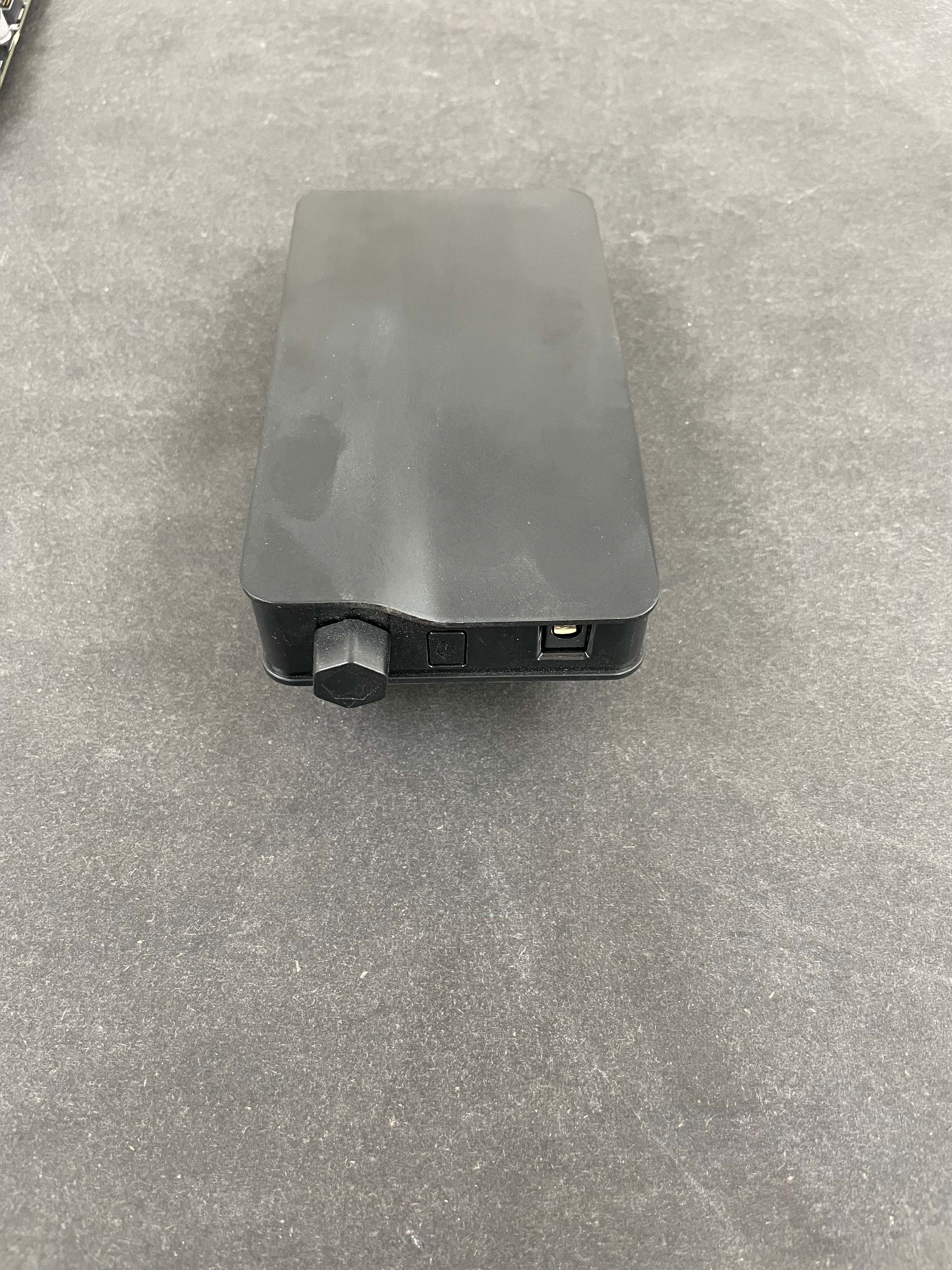
2AK7R-02661Digital Signal Transceiver for Entertainment System

RedSeat Entertainment
Digital Signal Transceiver for Entertainment System - FCC ID 2AK7R-02661 - RedSeat Entertainment
Click to zoom

Application Details

Equipment Class
DTS - Digital Transmission System
Date of Grant
Jul 23, 2023
Application Purpose
Original Equipment
Date of Application
Jul 19, 2023
Equipment Note
Digital Signal Transceiver for Entertainment System
Frequency Range
2406.00000000 - 2474.00000000
Company
RedSeat Entertainment
Country
United States

Documents & Files

Select a file to view
Users Manual

↗

Attestation Statements

↗
↗

Cover Letter(s)

↗
↗
↗

External Photos

↗

ID Label/Location Info

↗

Internal Photos

↗
↗

RF Exposure Info

↗

Test Report

↗
↗
↗

Test Setup Photos

↗

Document Text

Text extracted from the exhibit documents filed with the FCC. Open a document above to read the original.

Users Manual

REDSEAT ENTERTAINMENT Tremor FX Kinetic Seating System USER’S GUIDE r. 0909 © RED SEAT ENTERTAINMENT LLC SALT LAKE CITY, UT PHONE 801.268.4331 www.tremorfx.com TREMOR FX KINETIC SEATING SYSTEM USER’S GUIDE Contents USER’S GUIDE ........................................................................................................................................................................................2 What is Tremor FX? ........................................................................................................................................................................3 How Does It Work?.........................................................................................................................................................................4 Chairs ..............................................................................................................................................................................................4 Server ..............................................................................................................................................................................................5 Client ...............................................................................................................................................................................................5 TremorFX System Components.................................................................................................................................................6 TremorFX DSP Processor – Part Number 01234............................................................................................................6 TremorFX Amplifier - Part Number 01445 .......................................................................................................................6 Chair Actuator - Part Number 02110............................................................................................................................. 6 Reserving Seats ............................................................................................................................................................................. 7 Armrest Controls .......................................................................................................................................................................... 7 System Maintenance................................................................................................................................................................... 7 Warranty and Service.................................................................................................................................................................. 8 Safety Certifications .......................................................................................................................................9 What is Tremor FX? Tremor FX is a dynamic vibration technology that offers an enhanced, more immersive media experience. Unlike other audio enhancement solutions, Tremor FX was designed to enhance any media experience that involves an audio stream. Tremor FX processing technology focuses on the components of various soundtracks and how they are put together in movies and other media. This proprietary, patented audio processor makes use of varied outputs based upon intended effects and intensity. Because of this, the customizable chair offers different levels of intensity that individuals can modify according to their preference. The Tremor FX patented processor interprets audio streams and dynamically creates three frequency-based signals to separate actuators within the seat. Signals for ‘cinematic events’ with low frequency are sent to the seat actuator, while middle frequency ‘events’ are sent to the middle of the seat back and upper frequency ‘events’ are sent to the transducer in the upper back of each seat. This customization also means users can expect the chairs to respond intelligently as they turn the intensity up or down; the chairs do more than simply increase or decrease in vibration. For example, if a battle takes place in a film, on the lowest intensity setting, only the biggest explosions and gunshots will be felt. As the intensity is increased, however, secondary sounds and explosions can be felt in different parts of the seat, such as second-tier explosions happening farther from the main action on-screen, or single gunshots being felt in addition to their louder, more intense counterparts. Tremor FX was born as a kinetic seating system designed to enhance the movie watching experience in theaters. The system contains the audio processing unit, and is comprised of theater style chairs with individual controls; electronics governing the operation of the chairs; a server, Tremor FX Processor or wireless transmitter; and software. How Does It Work? At the heart of the Tremor FX system is the Tremor FX Processor. Three actuators, or vibrating units, embedded in each theater chair (two in the seatback, one in the bottom) receive digital signals from the configured DSP that correspond to the audio signals coming from the movie or media soundtrack, providing a sense that the viewer can “feel” the sound. Tremor FX chairs are the same size as most standard theater chairs, simplifying and streamlining the theater conversion process, and a modular design allows for easy upgrades and repairs to individual seats. The control box for an entire theater of seats takes up minimal space in the projection room and is smaller than a desktop computer tower. In movie theater installation, Tremor FX chairs need to be connected to the Tremor FX server in order to receive audio and messages. This is done with a basic Cat5e cable, first coming from the server and then into the electronic box, which controls the chairs in a daisy chain connection, eventually powering all chairs in that row. With the connecti…

Text truncated - open the document above for the full version.

Cover Letter(s)

050222-17 Request for Confidentiality Date: May 22, 2023 Subject: Confidentiality Request for: 2AK7R-02661 Pursuant to FCC 47 CFR 0.457(d) and 0.459 and/or IC RSP-100, Section 12.4, the applicant requests that a part of the subject application(s) be held confidential. Type of Confidentiality Requested Exhibit ☐ Short Term ☒ Permanent Block Diagrams ☐ Short Term --------------------------- External Photos ☐ Short Term ☐ Permanent * 1 Internal Photos ☐ Short Term ☒ Permanent Operation Description/Theory of Operation ☐ Short Term ☒ Permanent Parts List & Placement/BOM ☐ Short Term ☐ Permanent Tune-Up Procedure ☐ Short Term ☒ Permanent Schematics ☐ Short Term --------------------------- Test Setup Photos ☐ Short Term ☐ Permanent * 1 User’s Manual ______RedSeat Entertainment LLC______ has spent substantial effort in developing this product and it is one of the first of its kind in industry. Having the subject information easily available to "competition" would negate the advantage they have achieved by developing this product. Not protecting the details of the design will result in financial hardship. Permanent Confidentiality: The applicant requests the exhibits listed above as permanently confidential be permanently withheld from public review due to materials that contain trade secrets and proprietary information not customarily released to the public. Short-Term Confidentiality for FCC Applications: The applicant requests the exhibits selected above as short term confidential be withheld from public view for a period of __ (specify number of days not to exceed 180) 2 ___ days from the date of the Grant of Equipment Authorization and prior to marketing. This is to avoid premature release of sensitive information prior to marketing or release of the product to the public. Applicant is also aware that they are responsible to notify ACB in the event information regarding the product or the product is made available to the public before the requested period has expired. ACB will then release the documents listed above for public disclosure pursuant to FCC Public Notice DA 04-1705. Short Term Confidentiality for Industry Canada Applications: Starting May 2022, ISED will recognize short term confidentiality on certain exhibits until the intended date of marketing. The applicant requests the exhibits selected above as short term confidential be withheld from public view until: (specify ISED expiration date / date of marketing) . Sincerely, By: _Agent for RedSeat Entertainment__ _C.L. P(Les) Payne III__________ (Signature/Title 3 ) (Print name) 1 - The asterisked items (*) require further information to be provided to ACB before permanent confidentiality will be extended to these exhibits. Please refer to FCC KDB 726920 and the specific Document link for D01 found at: https://apps.fcc.gov/oetcf/kdb/forms/FTSSearchResultPage.cfm?switch=P&id=41731 and review section II, 3) regarding specific information that must accompany these requests. 2 - Please refer to https://acbcert.com/documents/misc-docs/Memo-Short-Term-Vs-Standard-Confidentiality.pdf for complete details. 3 - Must be signed by applicant contact given for applicant on the FCC site, or by the authorized agent if an appropriate authorized agent letter has been provided. Letters should be placed on appropriate letterhead.

Cover Letter(s)

21 May 2023 Atten:Director of Certification American Certification Body, Inc. 6731 Whittier Avenue, Suite C110 McLean, VA 22101 To Whom It May Concern RedSeat Entertainment LLC is submitting the following product which shall contain an unlicensed DTS radio transmitting device subject to US CFR 47 Part 15.247 Rules and Regulations and shall bear the following in accordance to the requirements: FCC ID: 2AK7R-02661Part Number: 02661Description: Amplifier Les Payne (Agent for RedSeat Entertainment LLC) Facility Manager DNB Engineering Inc 1100 E Chalk Creek Road Coalville, UT 84017

External Photos

Bottom of EUT Top of EUT Top View - Other End Side View One Side View Two

ID Label/Location Info

Label exhibit: Material: Mylar - printed with a marking and labeling system.

Internal Photos

Top of PCB Top of PCB - 2

Internal Photos

Bottom of PCB Radio Circuit Placement Note: u.fl connector is for testing purposes only. Bottom of PCB shown in chassis Top of PCB shown in Chassis - 1 Top of PCB shown in Chassis - 2

RF Exposure Info

Customer: Model: FCC ID: IC ID: Classification: MPE Calculator Lowest Frequency2404.000MHz Highest Frequency2476.000MHz Wavelength (lowest frequency)0.125m Antenna aperture (1/4 wavelength radiator assumed)0.031m Far Field Distance1.560cm Power (Antenna Conducted)-0.1500dBm Ant Gain dBi0.5000dB Cable Loss0.0000dB ERP dBm0.3500dB ERP mW1.0839mW R20.0000cm S0.000216mW/cm^2 Occupational/Controlled Exposure Limitinchescmtime OSHA10.000mW/cm^27.87420.0006 FCC5.000mW/cm^27.87420.0006 IC3.165mW/cm^27.87420.0006 General Population/Uncontrolled Exposure Limit OSHA10.000mW/cm^27.87420.0006 FCC1.000mW/cm^27.87420.00030 IC0.535mW/cm^27.87420.0006 RedSeat Entertainment LLC GT Throne Amplifier 2AK7R-02661 Notes DTS Calculations CFR 47 Part 1.1310 Portable General Population RF Exposure Standards

Test Report

2.4GHz Mini Antenna, SMTP/N 2450AT18A100 Detail Specification: Page 1 of 5 *Efficiency based on Johanson's standard evaluation board ±± ±± ±± www.johansontechnology.com 4001 Calle Tecate • Camarillo, CA 93012 • TEL 805.389.1166 FAX 805.389.1821 Ver. 3.0 2018 Johanson Technology, Inc. All Rights Reserved "High Frequency Ceramic Solutions" Part Number 7/9/2018 Avg. Rad Efficiency* Let us help you with the antenna design, optimization, and tuning! 2450AT18A100 2400 - 2500 76% General Specifications Frequency (MHz) 18 months max. -40 to +125°C -40 to +125°C 3000 Return Loss (dB) Impedance Input Power Storage Period Storage Temperature Operating Temperature Reel Quantity 50 Ω 2 Watts max. (CW) Johanson Technology, Inc. reserves the right to make design changes without notice. All sales are subject to Johanson Technology, Inc. terms and conditions. e.g. 2450AT18A100(E or S)100% Tin Packing Style Evaluation Board 2450AT18A100-EBSMA (see page 2&3 for details) Bulk (loose) T & R Suffix = E or S Suffix = E P/N Suffix Mechanical Dimensions In L 0.1260.0083.200.2 W 0.0630.0081.600.2 T 0.0511.30+.004/-.008 +0.1/-0.2 a 0.0200.0120.500.3 Terminal Configuration Function FEED NC No. 1 2 mm e.g. 2450AT18A100E e.g. 2450AT18A100SSuffix = S Part Number Explanation Peak Gain (dBi typ.) Average Gain (dBi typ.) 0.5 -0.5 9.5 min. ① ② L W a T Want the layout file? Request it at: www.johansontechnology.com/ask-a-question 2.4GHz Mini Antenna, SMTP/N 2450AT18A100 Detail Specification: Page 2 of 5 JTI P/N for Matching Circuit: Cap (1.0pF): 500R07S1R0BV4T Inductor (2.7nH): L-07C2N7SV6T Inductor (3.9nH): L-07C3N9SV6T www.johansontechnology.com 4001 Calle Tecate • Camarillo, CA 93012 • TEL 805.389.1166 FAX 805.389.1821 Ver. 3.0 2018 Johanson Technology, Inc. All Rights Reserved "High Frequency Ceramic Solutions" 7/9/2018 Mounting Considerations 1: Evaluation Board Johanson Technology, Inc. reserves the right to make design changes without notice. All sales are subject to Johanson Technology, Inc. terms and conditions. GND NO GND Units in mm ) ) 13.5mm 6.5mm 39.5mm 6.5mm 50Ω Feed Line Antenna 4mm ) Matching Component JTI P/Ns: L-14C2N7JV4 L-14C2N2JV4 * 2.6 4.2 1.6 1.9 0.4 2.7nH 1.0pF 3.9nH To order a pre-tuned 50Ω EVB with a female SMA connector click here: www.johansontechnology.com/request-a-sample Reference p/n: 2450AT18A100-EBSMA 2.4GHz Mini Antenna, SMTP/N 2450AT18A100 Detail Specification: Page 3 of 5 Return Loss with matching circuit @ +25CVSWR with matching circuit @ +25C and +125C www.johansontechnology.com 4001 Calle Tecate • Camarillo, CA 93012 • TEL 805.389.1166 FAX 805.389.1821 Ver. 3.0 2018 Johanson Technology, Inc. All Rights Reserved "High Frequency Ceramic Solutions" 7/9/2018 Mounting Considerations 1: Typical Electrical Performance (T=25°C) Johanson Technology, Inc. reserves the right to make design changes without notice. All sales are subject to Johanson Technology, Inc. terms and conditions. 2.4GHz Mini Antenna, SMT P/N 2450AT18A100 Detail Specification: Page 4 of 5 www.johansontechnology.com 4001 Calle Tecate • Camarillo, CA 93012 • TEL 805.389.1166 FAX 805.389.1821 Ver. 3.0 2018 Johanson Technology, Inc. All Rights Reserved "High Frequency Ceramic Solutions" 7/9/2018 Mounting Considerations 1: Antenna Performance Johanson Technology, Inc. reserves the right to make design changes without notice. All sales are subject to Johanson Technology, Inc. terms and conditions. Z X (0°) Y X (0°) Typical 2D radiation patterns @ 2.44GHz YZ-plane XZ-plane XY-plane Z (0°) Y XY cut @2.45GHz Vertical Horizontal XZ cut @2.45GHz Vertical Horizontal YZ cut @2.45GHz Vertical Horizontal 2.4GHz Mini Antenna, SMTP/N 2450AT18A100 Detail Specification: Page 5 of 5 www.johansontechnology.com 4001 Calle Tecate • Camarillo, CA 93012 • TEL 805.389.1166 FAX 805.389.1821 Ver. 3.0 2018 Johanson Technology, Inc. All Rights Reserved Johanson Technology, Inc. reserves the right to make design changes without notice. All sales are subject to Johanson Technology, Inc. terms and conditions. Soldering Information RoHS Compliance Packaging information For layout review contact our Applications Team at: "High Frequency Ceramic Solutions" Antenna tuning, optimization, and validation services: For more antennas and to download measured S-parameters, go to: MSL Info 7/9/2018 www.johansontechnology.com/ipc-antenna-services www.johansontechnology.com/antennas www.johansontechnology.com/ipcsoldering-profile www.johansontechnology.com/msl-rating www.johansontechnology.com/tape-reel-packaging www.johansontechnology.com/ask-a -question www.johansontechnology.com/rohs-compliance Need help designing the antenna in? Use our antenna design services! www.johansontechnology.com/ipc-antenna-services We provide 2 free layout reviews and if you need us to tune and characterize the antenna on your product (inside anechoic chamber) we can do that too. Small lab fee may apply for the latter.

Test Report

Application for Certification For a Transmitter. RedSeat Entertainment LLC 6440 South Wasatch Blvd., Suite 105 Holladay, UT 84121 GT Chair M/N: 02661 FCC ID: 2AK7R-02661 REPORT # UT16085A-003 This report was prepared in accordance with the requirements of the FCC Rules and Regulations Part 2, Subpart J, 2.1033, Part 15.247, RSS-247 Issue 2, and other applicable sections of the rules as indicated herein. Prepared By: DNB Engineering, Inc. 1100 E Chalk Creek Road Coalville, UT 84017 21 May 2023 TABLE OF CONTENTS Paragraph numbers in this report follow the application section numbers found in the FEDERAL COMMUNICATIONS COMMISSION Rules and Regulations, Part 2, Subpart J for Certification of electronic equipment. TABLE OF CONTENTS................................................................................................................2 1.0ADMINISTRATIVE DATA...................................................................................3 1.1Certifications and Qualifications............................................................................3 1.2Measurement Repeatability Information.................................................................3 1.3Test Equipment List................................................................................................4 1.4Test Summary Cross Reference..............................................................................5 1.5Measurement Uncertainty.......................................................................................5 2.1033 (b,2)FCC Identifier.........................................................................................................7 2.1033 (b,3)Installation and Operating Instructions...................................................................8 2.1033 (b,4)Brief Description of Circuit Function.....................................................................8 2.1033 (b,5)Block Diagram........................................................................................................8 2.1033 (b,7)Equipment Photographs..........................................................................................8 2.1033 (b,6)Report of Measurements ........................................................................................9 15.203Antenna Requirement ..................................................................10 15.207Conducted Emissions....................................................................11 15.209Radiated Emissions (General Provisions) ....................................15 15.247 (b,2)Output Power (DTS).....................................................................18 15.247 (e) Power Spectral Density (PSD)......................................................22 15.247 (d)Band-edge RF Conducted.............................................................26 15.247 (a,2)DTS Bandwidth............................................................................30 15.247 (d)Conducted Spurious......................................................................34 15.247 (d)Radiated Spurious Emissions........................................................47 15.247 (d)Restricted Bands...........................................................................51 End of Report UT16085A-003.....................................................................................................77 Page 2 of 77 1.0ADMINISTRATIVE DATA 1.1Certifications and Qualifications I certify that DNB Engineering, Inc conducted the tests performed in order to obtain the technical data presented in this application. Also, based on the results of the enclosed data, I have concluded that the equipment tested meets or exceeds the requirements of the Rules and Regulations governing this application. 1.2Measurement Repeatability Information The test data presented in this report has been acquired using the guidelines set forth in FCC Part 2.1031 through 2.1057, Part 15. The test results presented in this document are valid only for the equipment identified herein under the test conditions described. Repeatability of these test results will only be achieved with identical measurement conditions. These conditions include: The same test distance, EUT Height, Measurement Site Characteristics, and the same EUT System Components. The system must have the same Interconnecting Cables arranged in identical placement to that in the test set-up, with the system and/or EUT functioning in the identical mode of operation (i.e. software and so on) as on the date of the test. Any deviation from the test conditions and the environment on the date of the test may result in measurement repeatability difficulties. All changes made to the EUT during the course of testing as identified in this test report must be incorporated into the EUT or identical models to ensure compliance with the FCC regulations. C. L. Payne III (Para. 1.1) Facility Manager Coalville Facility. DNB Engineering, Inc. Tel. (435) 336-4433 FAX (435) 336-4436 Page 3 of 77 1.3Test Equipment List TEST EQUIPMENT LIST - CONDUCTED EMISSIONS DescriptionManufacturerModel No.Asset #Serial #Cal Due LISN Fisher Custom Communications FCCLISN5032401U-286202003 Feb 2024 Site 1 CE CableDNBN/AU-400BN/A01 Dec 2023 Spectrum Analyzer Rhode & SchwarzFSV30U-24810136727 Aug 2023 TILE Software ETS Lindgren3.4.11.13U-317811200607 Mar 2024 TEST EQUIPMENT LIST - RADIATED EMISSIONS DescriptionManufacturerModel No.Asset #Serial #Cal Due Pre-AmplifierHewlett Packard8447DU-0682727A0618404 Aug 2023 Pre-AmplifierDNBS-21GU-095U-095-103 Feb 2024 Site 1 RE CableDNBN/AU-400BN/A01 Dec 2023 High Freq CableTRU Corp210U-066 TRU-21B1111-080M 08 Feb 2024 BiConiLog AntennaETS - Lindgren3142EU-25515497303 Sep 2023 DRG Horn AntennaAH SystemsSAS-571U-07141711 Jul 2023 Spectrum Analyzer Rhode & SchwarzFSV30U-24810136727 Aug 2023 TILE SoftwareETS- Lindgren3.4.11.13U-317811200607 Mar 2024 TEST EQUIPMENT LIST - ANTENNA CONDUCTED DescriptionManufacturerModel No.Asset #Serial #Cal Due S…

Text truncated - open the document above for the full version.

Test Report

Client:RedSeat Entertainment LLCDate: 7 May 2023DNB Job: 16085 EUT: GT ChairModel No: 02661 Requirement: Conducted spurious emission <20dBof peakTech: CL Payne Mid Channel: 2442 MHzRequirement = -20.44 dBmResult: Pass Frequency range:12.515GHzto18.7575GHz Page 41 of 77 Client:RedSeat Entertainment LLCDate: 7 May 2023DNB Job: 16085 EUT: GT ChairModel No: 02661 Requirement: Conducted spurious emission <20dBof peakTech: CL Payne Mid Channel: 2442 MHzRequirement = -20.44 dBmResult: Pass Frequency range:18.7575GHzto25GHz Page 42 of 77 Client:RedSeat Entertainment LLCDate: 7 May 2023DNB Job: 16085 EUT: GT ChairModel No: 02661 Requirement: Conducted spurious emission <20dBof peakTech: CL Payne High Channel: 2474 MHzRequirement = -20.130 dBmResult: Pass Frequency range:30MHzto6.2725GHz Page 43 of 77 Client:RedSeat Entertainment LLCDate: 7 May 2023DNB Job: 16085 EUT: GT ChairModel No: 02661 Requirement: Conducted spurious emission <20dBof peakTech: CL Payne High Channel: 2474 MHzRequirement = -20.130 dBmResult: Pass Frequency range:6.2725GHzto12.515GHz Page 44 of 77 Client:RedSeat Entertainment LLCDate: 7 May 2023DNB Job: 16085 EUT: GT ChairModel No: 02661 Requirement: Conducted spurious emission <20dBof peakTech: CL Payne High Channel: 2474 MHzRequirement = -20.130 dBmResult: Pass Frequency range:12.515GHzto18.7575GHz Page 45 of 77 Client:RedSeat Entertainment LLCDate: 7 May 2023DNB Job: 16085 EUT: GT ChairModel No: 02661 Requirement: Conducted spurious emission <20dBof peakTech: CL Payne High Channel: 2474 MHzRequirement = -20.130 dBmResult: Pass Frequency range:18.7575GHzto25GHz Page 46 of 77 15.247 (d)Radiated Spurious EmissionsANSI C63.10 Clause 11.12.2.7 An additional consideration when performing conducted measurements of restricted-band emissions is that unwanted emissions radiating from the EUT cabinet, control circuits, power leads, or intermediate circuit elements will likely go undetected in a conducted measurement configuration. To address this concern, a radiated test shall be performed to ensure that emissions emanating from the EUT cabinet (rather than from the antenna port) also comply with the applicable limits. For these cabinet radiated spurious emission measurements, the EUT transmit antenna may be replaced with a termination matching the nominal impedance of the antenna. Procedures for performing radiated measurements are specified in 6.3, 6.5, and 6.6. All detected emissions shall comply with the applicable requirements. This test is required for any spurious emission or modulation product that falls in an Unrestricted Band, as defined in Section 15.209. It must be performed with the highest gain of each type of antenna proposed for use with the EUT. Use the following spectrum analyzer settings: Span = wide enough to fully capture the emission being measured RBW = 1 MHz for f ≥ 1 GHz, 100 kHz for f < 1 GHz VBW = ≥ RBW Sweep = auto Detector function = peak Trace = max hold Follow the guidelines in ANSI C63.10-2013with respect to maximizing the emission by rotating the EUT, measuring the emission while the EUT is situated in three orthogonal planes (if appropriate), adjusting the measurement antenna height and polarization, etc. A pre-amp and a high pass filter are required for this test, in order to provide the measuring system with sufficient sensitivity. Allow the trace to stabilize. The peak reading of the emission, after being corrected by the antenna factor, cable loss, pre-amp gain, etc., is the peak field strength, which must comply with the limit specified in Section 15.35(b). Submit this data. Now repeat the measurement using the average detector of the spectrum analyzer. Submit this data. Note 1:Limit listed is the general limit as specified in 15.209 in order to show compliance with the restricted bands of operation as well as the out of band limit in 15.247. No other identifiable signals were observed in the restricted bands as specified in 15.205. Note 2:Highest frequency investigated was the tenth harmonic of the fundamental, no radiated emissions were detected above the 1st harmonic. Page 47 of 77 Client:RedSeat Entertainment LLCDate: 9 Oct 2022DNB Job: 16085 EUT: GT ChairModel No: 02661 Requirement: General limit of 15.209Tech: CL Payne Low Channel: 2406Result: Pass RADIATED SPURIOUS Freq (MHz) Meter (dBuV/m) Pre-Amp (dB) Cable (dB) Antenna (dB) Corrected (dBuV/m) Limit (dBuV/m) Delta (dB) PolarityTypeAxis 4812.000 35.1625.745.9633.1048.4974.00-25.51VPeakN/A 4812.000 24.1425.745.9633.1037.4754.00-16.53VAveN/A 7218.000 34.5525.267.6235.7852.6974.00-21.31VPeakN/A 7218.000 24.1025.267.6235.7842.2454.00-11.76VAveN/A 9624.000 33.9025.059.1037.9555.9074.00-18.10VPeakN/A 9624.000 20.5225.059.1037.9542.5254.00-11.48VAveN/A 12030.000 32.9324.6910.0240.0258.2874.00-15.72VPeakN/A 12030.000 20.7624.6910.0240.0246.1154.00-7.89VAveN/A 4812.000 35.0025.745.9633.1048.3374.00-25.67HPeakN/A 4812.000 22.2725.745.9633.1035.6054.00-18.40HAveN/A 7218.000 32.7025.267.6235.7850.8474.00-23.16HPeakN/A 7218.000 20.2325.267.6235.7838.3754.00-15.63HAveN/A 9624.000 32.8025.059.1037.9554.8074.00-19.20HPeakN/A 9624.000 20.4525.059.1037.9542.4554.00-11.55HAveN/A 12030.000 32.3124.6910.0240.0257.6674.00-16.34HPeakN/A 12030.000 20.6924.6910.0240.0246.0454.00-7.96HAveN/A Page 48 of 77 Client:RedSeat Entertainment LLCDate: 9 Oct 2022DNB Job: 16085 EUT: GT ChairModel No: 02661 Requirement: General limit of 15.209Tech: CL Payne Mid Channel: 2442Result: Pass RADIATED SPURIOUS Freq (MHz) Meter (dBuV/m) Pre-Amp (dB) Cable (dB) Antenna (dB) Corrected (dBuV/m) Limit (dBuV/m) Delta (dB) PolarityTypeAxis 4884.000 35.7025.726.0133.1849.1774.00-24.83VPeakN/A 4884.000 21.9725.726.0133.1835.4454.00-18.56VAveN/A 7326.000 33.4425.237.6935.9051.7974.00-22.21VPeakN/A 7326.000 20.2225.237.6935.9038.5754.00-15.43VAveN/A 9768.000 33.5124.999.1038.0155.6274.00-18.38VPeakN/A 9768.000 19.6524.999.1038.0141.7654.00-12.24VAveN/A 12210.000 33.1324.6510.1340.1558.7574.00-15.25VPeakN/A 12210.000 20.6524.6510.1340.1546.2754…

Text truncated - open the document above for the full version.

Test Setup Photos

Test Set Up Photo - Conducted Emissions Test Set Up Photo - Radiated Emissions Test Set Up Photo - Radiated Spurious Emissions Test Set Up Photo - Antenna Conducted

Contact Information

Applicant

Tim Hansen(Company Contact)
[email protected]801-268-4331Fax: 801-365-1256

Test Firm

DNB Engineering, Inc.Michael Neis
[email protected]714-870-7781Fax: 714-870-5081

Technical Specifications

#Rule PartsFrequency RangePower Output
115C2.41 GHz - 2.47 GHz1.00 mW
Confidentiality
Long Term
Grant Notes
Output power listed is conducted. RF exposure compliance is addressed for 1.1310 and 2.1091 MPE limits at the distance specified in the filing, therefore, this device may be used in mobile configurations. Installers and end-users must be provided with transmitter installation and operation conditions for satisfying RF exposure compliance. The antenna(s) used for this transmitter must not transmit simultaneously with any other antenna or transmitter, except in accordance with FCC multi- transmitter product procedures. Grantee must provide installation and operating instructions for complying with FCC multi-transmitter product procedures and RF exposure compliance.

Other Applications from RedSeat Entertainment

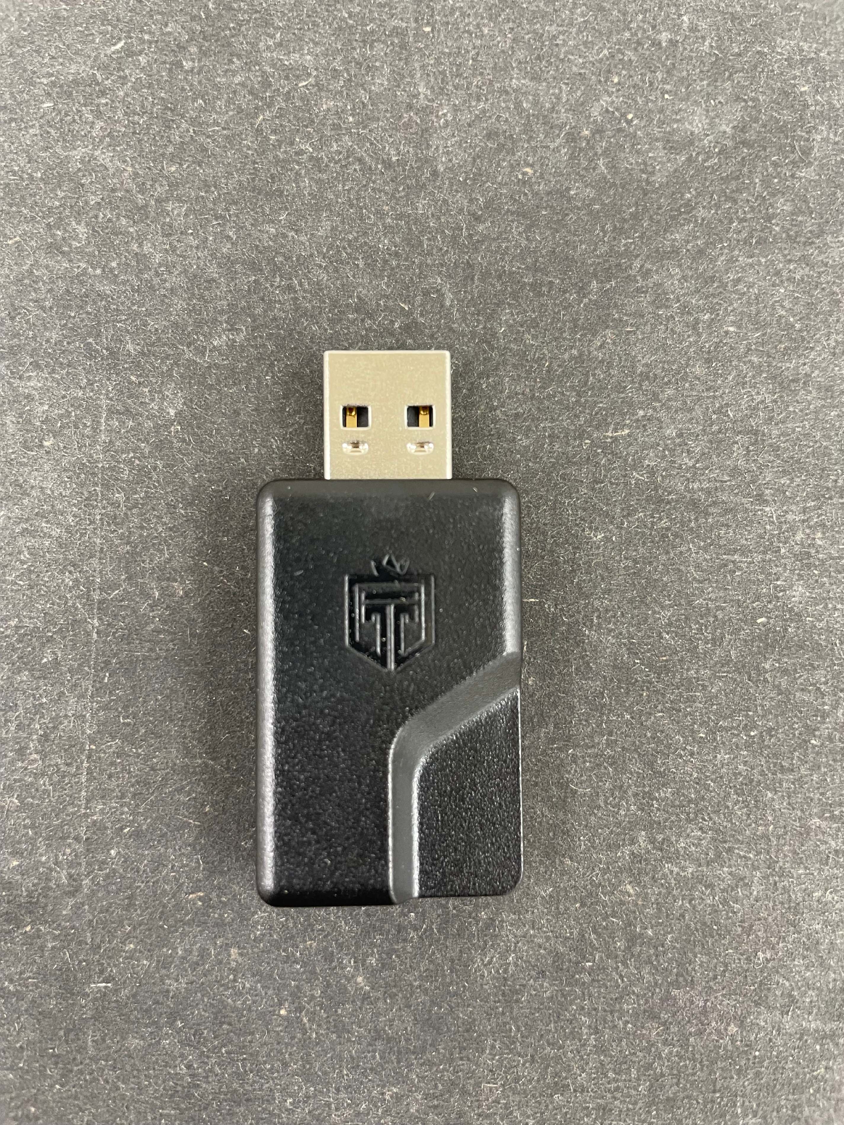
Digital Signal USB Transceiver for Entertainment System - FCC ID 2AK7R-04337 - RedSeat Entertainment
2AK7R-04337

Digital Signal USB Transceiver for Entertainment System

Nov 19, 2023

Equipment Class

DTS - Digital Transmission System