Text extracted from the exhibit documents filed with the FCC. Open a document above to read the original.
TABLE OF CONTENTS Thank You What’s Included Chair Assembly Electronics Headphones & Speakers Safety and Certifications 3 4–5 6–9 10–11 12 13 Victory is sweeter on a throne. Game ON! THANK YOU! Thank you for purchasing the GT Throne! We’re confident that this immersive chair will take your gaming experience to a royally different dimension—one where the loot is always bountiful, every kill leads to a streak, and every championship and chicken dinner belongs to you. A member of our team has personally inspected your package, but if you have any questions, concerns or feedback, please let us know. If you need additional help assembling your chair and electronics, visit our resources page at www.gtthrone.com [email protected] Scan this QR code for electronics setup videos and additional resources @GTThrone @gtthrone 3 WHAT’ S INCLUDED Chair Parts Electronics 4 × Plastic Screw Covers 4 × Side Cover Screws 1 × Seat 1 × Base 5 × Casters 1 × Plastic Base Cover (Left) 1 × Plastic Side Cover (Left) 1 × Plastic Base Cover (Right) 1 × Plastic Side Cover (Right) 1 × GT Processor FCC ID: 2AK7R-04337 1 × GT Receiver FCC ID: 2AK7R-02661 1 × Power Supply 1 × Trip Wire 1 × Allen Key 1 × Headrest Cushion 1 × Lumbar Cushion 1 × Hydraulic Unit Plastic Cover 6 × Small Screws 1 × Backrest 2 × Arm Rest 1 × Control Unit 1 × Hydraulic Unit 1 × GT Receiver Mounting Plate 1 × Power Cord 4 5 CHAIR ASSEMBLY Attach the wheels to the base by pushing and clicking in. Step 3 Remove backrest side screws with MS Allen key. 6 Step 2 Install the hydraulic pump into the center of the base, with plastic cover sliding onto pump. Step 4 Line up backrest side screw holes with the seat base metal brackets. Step 5 Tighten screws to secure backrest to seat base. Step 7 Attach the metal mounting plate to the GT receiver with the 4 small screws included with the mounting plate. Step 6 Fix the plastic covers to the sides of the metal brackets. Attach the seat covers first, then click the side covers into the seat cover. Step 8 Line up one armrest bracket to the bottom 4 holes on the LEFT side. Place the GT Receiver’s bracket on top of the armrest. Using the MS Allen key, tighten the 4 screws with washer on the outside. 7 1 CHAIR ASSEMBLY Step 9 Attach the other armrest on the RIGHT side without the GT Receiver. NOTE: the width of the armrest can be decided when screwing into the bottom of the chair Step 11 Fix the metal control unit to the base of the seat (4 screws have been fixed to the seat based prior to delivery). Assure the front arrow on the metal control unit faces outward and the control lever is on the right side of the chair. 8 Step 10 Attach actuator wires to the back of the GT Receiver. The backrest actuator plugs in on the opposite side of the intensity knob. The two seat actuator wires plug into the two ports closet to the front of the chair. Step 12 Insert the hydraulic unit into the opening of the control unit. Finished! NOTE: The height of the chair can be controlled with control lever on the right side. The recline of the chair can be controlled by loosening/tightening the knob beneath the seat. Rocking can be locked by pushing in the control lever. 9 ELECTRONICS Step 1 Power your chair by plugging the power cord into the GT trip wire. Plug the GT trip wire into the GT receiver. Step 2 Take the GT USB Processor and plug into an open usb port on your PC. Step 4 Once both electronics pieces are powered, they should automatically pair and both show green. If they both show red then they will need to be re-paired. Step 5 PAIRING – turn both pieces on by twisting each knob clockwise. First, push the sync button on the GT Receiver followed by the GT Processor. If they both do not turn green please see our trouble . The knob on the GT Receiver will control the intensity and frequency of the chair’s vibration. . shooting section on the resource page of www.gtthrone.com 10 11 HEADPHONES & SPEAKERS Digital USB Headphone A headphone with a USB connection will need to be connected to a USB port on your PC. You will then need to configure your PC to use 2 audio outputs while you are using the GT Throne and a USB headset at the same time. Please see the video on the electronic set-up page at www.gtthrone.com with instructions on how to do so on Windows computers. USB DEVICE USAGE Connect USB device to computer. Once chair is powered, press the pairing button. Enjoy the experience! CHAIR DEVICE USAGE Connect chair device to the provided power cord. Press pairing button on USB device. Enjoy the experience! Safety and Certifications Changes or modification to this unit not expressly approved by the party responsible for compliance could void the user's authority to operate the equipment. RF Exposure Information FCC ID:2AK7R-02661 This equipment complies with FCC radiation exposure limits set forth for an uncontrolled environment. In order to avoid the possibility of exceeding the FCC radio frequency exposure limits, human proximity to the antenna shall not be less than 20 cm during normal operation. RF Exposure Information FCCID: 2AK7R-04337 This equipment complies with FCC radiation exposure for SAR exclusion limits. This device complies with the SAR exclusion limits at 5mm. Contact Information RedSeat Entertainment, LLC. 6440 South Wasatch Blvd. Ste 105 Holladay, Utah 84121 (801)268-4331 www.gtthrone.com This device complies with Part 15 of the FCC Rules and this device also contains license-exempt transmitter(s)/receiver(s). Operation is subject to the following two conditions: (1) this device may not cause harmful interference, and (2) this device must accept any interference received, including interference that may cause undesired operation. This equipment complies with FCC radiation exposure limits set forth for an uncontrolled environment. This equipment is not in direct contact with the body of the user under normal operating conditions. This transmitter must not be co-located or operating in conjunction with any other anten…
Text truncated - open the document above for the full version.
050222-17 Request for Confidentiality Date: 16 Sep 2023 Subject: Confidentiality Request for: 2AK7R-04337 Pursuant to FCC 47 CFR 0.457(d) and 0.459 and/or IC RSP-100, Section 12.4, the applicant requests that a part of the subject application(s) be held confidential. Type of Confidentiality Requested Exhibit ☐ Short Term ☒ Permanent Block Diagrams ☐ Short Term --------------------------- External Photos ☐ Short Term ☐ Permanent * 1 Internal Photos ☐ Short Term ☒ Permanent Operation Description/Theory of Operation ☐ Short Term ☒ Permanent Parts List & Placement/BOM ☐ Short Term ☐ Permanent Tune-Up Procedure ☐ Short Term ☒ Permanent Schematics ☐ Short Term --------------------------- Test Setup Photos ☐ Short Term ☐ Permanent * 1 User’s Manual ______RedSeat Entertainment LLC______ has spent substantial effort in developing this product and it is one of the first of its kind in industry. Having the subject information easily available to "competition" would negate the advantage they have achieved by developing this product. Not protecting the details of the design will result in financial hardship. Permanent Confidentiality: The applicant requests the exhibits listed above as permanently confidential be permanently withheld from public review due to materials that contain trade secrets and proprietary information not customarily released to the public. Short-Term Confidentiality for FCC Applications: The applicant requests the exhibits selected above as short term confidential be withheld from public view for a period of __ (specify number of days not to exceed 180) 2 ___ days from the date of the Grant of Equipment Authorization and prior to marketing. This is to avoid premature release of sensitive information prior to marketing or release of the product to the public. Applicant is also aware that they are responsible to notify ACB in the event information regarding the product or the product is made available to the public before the requested period has expired. ACB will then release the documents listed above for public disclosure pursuant to FCC Public Notice DA 04-1705. Short Term Confidentiality for Industry Canada Applications: Starting May 2022, ISED will recognize short term confidentiality on certain exhibits until the intended date of marketing. The applicant requests the exhibits selected above as short term confidential be withheld from public view until: (specify ISED expiration date / date of marketing) . Sincerely, By: _Agent for RedSeat Entertainment__ _C.L. P(Les) Payne III__________ (Signature/Title 3 ) (Print name) 1 - The asterisked items (*) require further information to be provided to ACB before permanent confidentiality will be extended to these exhibits. Please refer to FCC KDB 726920 and the specific Document link for D01 found at: https://apps.fcc.gov/oetcf/kdb/forms/FTSSearchResultPage.cfm?switch=P&id=41731 and review section II, 3) regarding specific information that must accompany these requests. 2 - Please refer to https://acbcert.com/documents/misc-docs/Memo-Short-Term-Vs-Standard-Confidentiality.pdf for complete details. 3 - Must be signed by applicant contact given for applicant on the FCC site, or by the authorized agent if an appropriate authorized agent letter has been provided. Letters should be placed on appropriate letterhead.
16 Sep 2023 Atten: Director of Certification American Certification Body, Inc. 6731 Whittier Avenue, Suite C110 McLean, VA 22101 To Whom It May Concern RedSeat Entertainment LLC is submitting the following product which shall contain an unlicensed DTS radio transmitting device subject to US CFR 47 Part 15.247 Rules and Regulations and shall bear the following in accordance to the requirements: FCC ID: 2AK7R-04337 Part Number: 04337 Description: USB Transceiver Les Payne (Agent for RedSeat Entertainment LLC) Facility Manager DNB Engineering Inc 1100 E Chalk Creek Road Coalville, UT 84017
Bottom of EUT Top of EUT
Figure 1 - FCC Identifier on packaging FCC Label Placement Pursuant to FCC Part 2.925 paragraph (f) The FCC Identifier including the term “FCC ID” shall be in a size of type large enough to be readily legible, consistent with the dimensions of the equipment and its label. However, the type size for the FCC Identifier is not required to be larger than eight-point. If a device is so small that it is impractical to label it with the FCC Identifier in a font that is four-point or larger, and the device does not have a display that can show electronic labeling, then the FCC Identifier shall be placed in the user manual and must also either be placed on the device packaging or on a removable label attached to the device. The FCC Identifier is placed on the packaging and in the User Manual. From page 8 of the User Manual: FCC ID: 2AK7R-04337 This FCC ID number is only located in this manual and on the packaging, not on the device itself.
Top of PCB Top of PCB - 2 Bottom of PCB Radio Circuit Placement
Customer: Model: FCC ID: IC ID: Classification: MPE Calculator Lowest Frequency2404.000MHz Highest Frequency2476.000MHz Wavelength (lowest frequency)0.125m Antenna aperture (1/4 wavelength radiator assumed)0.031m Far Field Distance1.560cm Power (Antenna Conducted)-0.1500dBm Ant Gain dBi0.5000dB Cable Loss0.0000dB ERP dBm0.3500dB ERP mW1.0839mW R20.0000cm S0.000216mW/cm^2 Occupational/Controlled Exposure Limitinchescmtime OSHA10.000mW/cm^27.87420.0006 FCC5.000mW/cm^27.87420.0006 IC3.165mW/cm^27.87420.0006 General Population/Uncontrolled Exposure Limit OSHA10.000mW/cm^27.87420.0006 FCC1.000mW/cm^27.87420.00030 IC0.535mW/cm^27.87420.0006 Value Maximum conducted output power (mW)1.0839 Tune up tolerance (mW)1 Minimum Test Separation distance ≤ 5mm5 Frequency in GHz2.476 HeadLimb Formula = OP+TU/Separation*√Freq in GHzResult →0.656 3.007.50Pass HeadLimb Compared to Table 11.0839≤ 5mm24504.0010.00 Pass RedSeat Entertainment LLC GT USB 2AK7R-04337 Notes DTS Result Calculations SAR Test Exclusion per FDB 447498 D01 4.3.1a CFR 47 Part 1.1310 Portable SeparationERP mW Exemption Limit (mW) RF Exposure Freq MHz SAR Exclusion Standards Exemption Limit (mW) Result SAR Test Exclusion per RSS-102 Issue 5 Clause 2.5.1 General Population
Johanson Product Information for 2450AT18A0100001E Johanson Company: Johanson Technology inc. Deprecated P/N: 2450AT18A100E Datasheet Date: 06-30-2023 Description: Antennas, 1206, 2400-2500MHz, 2W, 0.5dBi (typ), Mini 2.45GHz Antenna, Ni/Sn (RoHS), 7" Reel Embossed Tape Life Cycle Stage: Active - Production AEC Q200 Qualified: No Schedule B: 8529.10.60.00 Harmonization Code: 8529.10.60.00 ITAR: No ECCN: EAR99 RoHS Compliance: Yes, RoHS 10/10 REACH: Yes Country of Origin: TW Product Family: Antennas Product Subfamily: Antennas Termination: Ni/Sn (RoHS) Marking: Orientation Mark Product Release Date: 11 January, 2006 Web Page Link: https://www.johansontechnology.com/antennas NCNR: No Thickness (Max): 0.055 Thickness (Min): 0.043 End Band (Min): 0.008 End Band (Max): 0.032 Standard Item: Yes Lead Time Typical (Weeks)*: *This can vary significantly so it is important to obtain a quotation with lead time for production planning purposes. 14 Length (Min): 0.118 Length (Max): 0.134 Width (Min): 0.055 Width (Max): 0.071 Packaging: 7" Reel Embossed Tape Packaging Qty: 3000 Operating Temp Range: -40°C to +125°C Storage Temp Range (Packaged): +5°C to +40°C with RH 20% to 70% Page 1/2 Storage Temp Range (Non Operating): -55°C to +125°C Powered by TCPDF (www.tcpdf.org) Page 2/2
2.4GHz Mini Antenna, SMTP/N 2450AT18A100 Detail Specification: Page 1 of 5 *Efficiency based on Johanson's standard evaluation board ±± ±± ±± www.johansontechnology.com 4001 Calle Tecate • Camarillo, CA 93012 • TEL 805.389.1166 FAX 805.389.1821 Ver. 3.0 2018 Johanson Technology, Inc. All Rights Reserved "High Frequency Ceramic Solutions" Part Number 7/9/2018 Avg. Rad Efficiency* Let us help you with the antenna design, optimization, and tuning! 2450AT18A100 2400 - 2500 76% General Specifications Frequency (MHz) 18 months max. -40 to +125°C -40 to +125°C 3000 Return Loss (dB) Impedance Input Power Storage Period Storage Temperature Operating Temperature Reel Quantity 50 Ω 2 Watts max. (CW) Johanson Technology, Inc. reserves the right to make design changes without notice. All sales are subject to Johanson Technology, Inc. terms and conditions. e.g. 2450AT18A100(E or S)100% Tin Packing Style Evaluation Board 2450AT18A100-EBSMA (see page 2&3 for details) Bulk (loose) T & R Suffix = E or S Suffix = E P/N Suffix Mechanical Dimensions In L 0.1260.0083.200.2 W 0.0630.0081.600.2 T 0.0511.30+.004/-.008 +0.1/-0.2 a 0.0200.0120.500.3 Terminal Configuration Function FEED NC No. 1 2 mm e.g. 2450AT18A100E e.g. 2450AT18A100SSuffix = S Part Number Explanation Peak Gain (dBi typ.) Average Gain (dBi typ.) 0.5 -0.5 9.5 min. ① ② L W a T Want the layout file? Request it at: www.johansontechnology.com/ask-a-question 2.4GHz Mini Antenna, SMTP/N 2450AT18A100 Detail Specification: Page 2 of 5 JTI P/N for Matching Circuit: Cap (1.0pF): 500R07S1R0BV4T Inductor (2.7nH): L-07C2N7SV6T Inductor (3.9nH): L-07C3N9SV6T www.johansontechnology.com 4001 Calle Tecate • Camarillo, CA 93012 • TEL 805.389.1166 FAX 805.389.1821 Ver. 3.0 2018 Johanson Technology, Inc. All Rights Reserved "High Frequency Ceramic Solutions" 7/9/2018 Mounting Considerations 1: Evaluation Board Johanson Technology, Inc. reserves the right to make design changes without notice. All sales are subject to Johanson Technology, Inc. terms and conditions. GND NO GND Units in mm ) ) 13.5mm 6.5mm 39.5mm 6.5mm 50Ω Feed Line Antenna 4mm ) Matching Component JTI P/Ns: L-14C2N7JV4 L-14C2N2JV4 * 2.6 4.2 1.6 1.9 0.4 2.7nH 1.0pF 3.9nH To order a pre-tuned 50Ω EVB with a female SMA connector click here: www.johansontechnology.com/request-a-sample Reference p/n: 2450AT18A100-EBSMA 2.4GHz Mini Antenna, SMTP/N 2450AT18A100 Detail Specification: Page 3 of 5 Return Loss with matching circuit @ +25CVSWR with matching circuit @ +25C and +125C www.johansontechnology.com 4001 Calle Tecate • Camarillo, CA 93012 • TEL 805.389.1166 FAX 805.389.1821 Ver. 3.0 2018 Johanson Technology, Inc. All Rights Reserved "High Frequency Ceramic Solutions" 7/9/2018 Mounting Considerations 1: Typical Electrical Performance (T=25°C) Johanson Technology, Inc. reserves the right to make design changes without notice. All sales are subject to Johanson Technology, Inc. terms and conditions. 2.4GHz Mini Antenna, SMT P/N 2450AT18A100 Detail Specification: Page 4 of 5 www.johansontechnology.com 4001 Calle Tecate • Camarillo, CA 93012 • TEL 805.389.1166 FAX 805.389.1821 Ver. 3.0 2018 Johanson Technology, Inc. All Rights Reserved "High Frequency Ceramic Solutions" 7/9/2018 Mounting Considerations 1: Antenna Performance Johanson Technology, Inc. reserves the right to make design changes without notice. All sales are subject to Johanson Technology, Inc. terms and conditions. Z X (0°) Y X (0°) Typical 2D radiation patterns @ 2.44GHz YZ-plane XZ-plane XY-plane Z (0°) Y XY cut @2.45GHz Vertical Horizontal XZ cut @2.45GHz Vertical Horizontal YZ cut @2.45GHz Vertical Horizontal 2.4GHz Mini Antenna, SMTP/N 2450AT18A100 Detail Specification: Page 5 of 5 www.johansontechnology.com 4001 Calle Tecate • Camarillo, CA 93012 • TEL 805.389.1166 FAX 805.389.1821 Ver. 3.0 2018 Johanson Technology, Inc. All Rights Reserved Johanson Technology, Inc. reserves the right to make design changes without notice. All sales are subject to Johanson Technology, Inc. terms and conditions. Soldering Information RoHS Compliance Packaging information For layout review contact our Applications Team at: "High Frequency Ceramic Solutions" Antenna tuning, optimization, and validation services: For more antennas and to download measured S-parameters, go to: MSL Info 7/9/2018 www.johansontechnology.com/ipc-antenna-services www.johansontechnology.com/antennas www.johansontechnology.com/ipcsoldering-profile www.johansontechnology.com/msl-rating www.johansontechnology.com/tape-reel-packaging www.johansontechnology.com/ask-a -question www.johansontechnology.com/rohs-compliance Need help designing the antenna in? Use our antenna design services! www.johansontechnology.com/ipc-antenna-services We provide 2 free layout reviews and if you need us to tune and characterize the antenna on your product (inside anechoic chamber) we can do that too. Small lab fee may apply for the latter.
Application for Certification For a Transmitter. RedSeat Entertainment LLC 6440 South Wasatch Blvd., Suite 105 Holladay, UT 84121 GT USB M/N: 04337 FCC ID: 2AK7R-04337 REPORT # UT16084A-002 This report was prepared in accordance with the requirements of the FCC Rules and Regulations Part 2, Subpart J, 2.1033, Part 15.247, RSS-247 Issue 2, and other applicable sections of the rules as indicated herein. Prepared By: DNB Engineering, Inc. 1100 E Chalk Creek Road Coalville, UT 84017 16 Sep 2023 TABLE OF CONTENTS Paragraph numbers in this report follow the application section numbers found in the FEDERAL COMMUNICATIONS COMMISSION Rules and Regulations, Part 2, Subpart J for Certification of electronic equipment. TABLE OF CONTENTS................................................................................................................2 1.0ADMINISTRATIVE DATA...................................................................................3 1.1Certifications and Qualifications............................................................................3 1.2Measurement Repeatability Information.................................................................3 1.3Test Equipment List................................................................................................4 1.4Test Summary Cross Reference..............................................................................5 1.5Measurement Uncertainty.......................................................................................5 2.1033 (b,2)FCC Identifier.........................................................................................................7 2.1033 (b,3)Installation and Operating Instructions...................................................................8 2.1033 (b,4)Brief Description of Circuit Function.....................................................................8 2.1033 (b,5)Block Diagram........................................................................................................8 2.1033 (b,7)Equipment Photographs..........................................................................................8 2.1033 (b,6)Report of Measurements ........................................................................................9 15.203Antenna Requirement ..................................................................10 15.207Conducted Emissions....................................................................11 15.209Radiated Emissions (General Provisions) ....................................15 15.247 (b,2)Output Power (DTS).....................................................................18 15.247 (e) Power Spectral Density (PSD)......................................................22 15.247 (d)Band-edge RF Conducted.............................................................26 15.247 (a,2)DTS Bandwidth............................................................................30 15.247 (d)Conducted Spurious......................................................................34 15.247 (d)Radiated Spurious Emissions........................................................47 15.247 (d)Restricted Bands...........................................................................51 End of Report UT16084A-002.....................................................................................................77 Page 2 of 78 1.0ADMINISTRATIVE DATA 1.1Certifications and Qualifications I certify that DNB Engineering, Inc conducted the tests performed in order to obtain the technical data presented in this application. Also, based on the results of the enclosed data, I have concluded that the equipment tested meets or exceeds the requirements of the Rules and Regulations governing this application. 1.2Measurement Repeatability Information The test data presented in this report has been acquired using the guidelines set forth in FCC Part 2.1031 through 2.1057, Part 15. The test results presented in this document are valid only for the equipment identified herein under the test conditions described. Repeatability of these test results will only be achieved with identical measurement conditions. These conditions include: The same test distance, EUT Height, Measurement Site Characteristics, and the same EUT System Components. The system must have the same Interconnecting Cables arranged in identical placement to that in the test set-up, with the system and/or EUT functioning in the identical mode of operation (i.e. software and so on) as on the date of the test. Any deviation from the test conditions and the environment on the date of the test may result in measurement repeatability difficulties. All changes made to the EUT during the course of testing as identified in this test report must be incorporated into the EUT or identical models to ensure compliance with the FCC regulations. C. L. Payne III (Para. 1.1) Facility Manager Coalville Facility. DNB Engineering, Inc. Tel. (435) 336-4433 FAX (435) 336-4436 Page 3 of 78 1.3Test Equipment List TEST EQUIPMENT LIST - CONDUCTED EMISSIONS DescriptionManufacturerModel No.Asset #Serial #Cal Due LISN Fisher Custom Communications FCCLISN5032401U-286202003 Feb 2024 Site 1 CE CableDNBN/AU-400BN/A01 Dec 2023 Spectrum Analyzer Rhode & SchwarzFSV30U-24810136727 Aug 2023 TILE Software ETS Lindgren3.4.11.13U-317811200607 Mar 2024 TEST EQUIPMENT LIST - RADIATED EMISSIONS DescriptionManufacturerModel No.Asset #Serial #Cal Due Pre-AmplifierHewlett Packard8447DU-0682727A0618404 Aug 2023 Pre-AmplifierDNBS-21GU-095U-095-103 Feb 2024 Site 1 RE CableDNBN/AU-400BN/A01 Dec 2023 High Freq CableTRU Corp210U-066 TRU-21B1111-080M 08 Feb 2024 BiConiLog AntennaETS - Lindgren3142EU-25515497303 Sep 2023 DRG Horn AntennaAH SystemsSAS-571U-07141711 Jul 2023 Spectrum Analyzer Rhode & SchwarzFSV30U-24810136727 Aug 2023 TILE SoftwareETS- Lindgren3.4.11.13U-317811200607 Mar 2024 TEST EQUIPMENT LIST - ANTENNA CONDUCTED DescriptionManufacturerModel No.Asset #Serial #Cal Due Spe…
Text truncated - open the document above for the full version.
Client:RedSeat Entertainment LLCDate: 7 Jul 2023DNB Job: 16084 EUT: GT USBModel No: 04337 Requirement: General limit of 15.209Tech: CL Payne High Channel: 2474Result: Pass RADIATED SPURIOUS Freq (MHz) Meter (dBuV) Pre-Amp (dB) Cable (dB) Antenna (dB/m) Corrected (dBuV/m) Limit (dBuV/m) Delta (dB) PolarityTypeAxis 4948.248 36.0025.625.9833.6149.9774.00-24.03VPeakX 4948.248 26.3825.625.9833.6140.3554.00-13.65VAveX 7422.372 32.7325.507.4237.1451.7974.00-22.21VPeakX 7422.372 21.6425.507.4237.1440.7054.00-13.30VAveX 9896.496 32.8424.949.1038.0655.0674.00-18.94VPeakX 9896.496 20.0024.949.1038.0642.2254.00-11.78VAveX 4948.248 37.1025.625.9833.6151.0774.00-22.93HPeakX 4948.248 28.3625.625.9833.6142.3354.00-11.67HAveX 7422.372 31.0625.507.4237.1450.1274.00-23.88HPeakX 7422.372 20.6125.507.4237.1439.6754.00-14.33HAveX 9896.496 32.5524.949.1038.0654.7774.00-19.23HPeakX 9896.496 19.7024.949.1038.0641.9254.00-12.08HAveX 4948.248 36.2125.625.9833.6150.1874.00-23.82VPeakY 4948.248 27.2025.625.9833.6141.1754.00-12.83VAveY 7422.372 32.6625.507.4237.1451.7274.00-22.28VPeakY 7422.372 20.1925.507.4237.1439.2554.00-14.75VAveY 9896.496 32.3624.949.1038.0654.5874.00-19.42VPeakY 9896.496 19.7724.949.1038.0641.9954.00-12.01VAveY 4948.248 35.1025.625.9833.6149.0774.00-24.93HPeakY 4948.248 24.1925.625.9833.6138.1654.00-15.84HAveY 7422.372 33.4025.507.4237.1452.4674.00-21.54HPeakY 7422.372 20.8325.507.4237.1439.8954.00-14.11HAveY 9896.496 33.1124.949.1038.0655.3374.00-18.67HPeakY 9896.496 20.0024.949.1038.0642.2254.00-11.78HAveY 4948.248 28.3425.625.9833.6142.3174.00-31.69VPeakZ 4948.248 22.9525.625.9833.6136.9254.00-17.08VAveZ 7422.372 24.5525.507.4237.1443.6174.00-30.39VPeakZ 7422.372 12.9125.507.4237.1431.9754.00-22.03VAveZ 9896.496 23.2224.949.1038.0645.4474.00-28.56VPeakZ 9896.496 10.7424.949.1038.0632.9654.00-21.04VAveZ 4948.248 27.9425.625.9833.6141.9174.00-32.09HPeakZ 4948.248 22.2525.625.9833.6136.2254.00-17.78HAveZ 7422.372 23.1025.507.4237.1442.1674.00-31.84HPeakZ 7422.372 12.1225.507.4237.1431.1854.00-22.82HAveZ 9896.496 22.7824.949.1038.0645.0074.00-29.00HPeakZ 9896.496 10.7324.949.1038.0632.9554.00-21.05HAveZ No readings were observed above the third harmonic Page 51 of 78 15.247 (d)Restricted BandsANSI C63.10-2013 Clause 11.12.2 11.12.2 Antenna-port conducted measurements 11.12.2.1 General Antenna-port conducted measurements may also be used as an alternative to radiated measurements for determining compliance in the restricted frequency bands requirements. If conducted measurements are performed, then proper impedance matching must be ensured and an additional radiated test for cabinet/case emissions is required. 11.12.2.2 General procedure for conducted measurements in restricted bands The general procedure for conducted measurements in restricted bands is as follows: a) Measure the conducted output power (in dBm) using the detector specified by the appropriate regulatory agency (see 11.12.2.3 through 11.12.2.5 for guidance regarding measurement procedures for determining quasi-peak, peak, and average conducted output power, respectively). b) Add the maximum transmit antenna gain (in dBi) to the measured output power level to determine the EIRP (see 11.12.2.6 for guidance on determining the applicable antenna gain). c) Add the appropriate maximum ground reflection factor to the EIRP (6 dB for frequencies # 30 MHz; 4.7 dB for frequencies between 30 MHz and 1000 MHz, inclusive; and 0 dB for frequencies > 1000 MHz). d) For MIMO devices, measure the power of each chain and sum the EIRP of all chains in linear terms (i.e., watts and mW). e) Convert the resultant EIRP to an equivalent electric field strength using the following relationship: E = EIRP ! 20 log d + 104.8 where E is the electric field strength in dBμV/m EIRP is the equivalent isotropically radiated power in dBm d is the specified measurement distance in m f) Compare the resultant electric field strength level with the applicable regulatory limit. g) Perform the radiated spurious emission test. Page 52 of 78 15.247 (d)Restricted Bands - continued Note: With respect to steps e) and f) a limit line (EIRP) based upon the dBuV/m limit was calculated and put on the plots to satisfy the requirement of step f) above. Formula is: ( E + 20 log d ) - 104.8 = ( EIRP limit ). The appropriate correction factor from step c) was included in the final calculation. Limit Calculation: Formula: E – 104.8 + 20log(3) – antenna gain – ground reflection factor 30 MHz - 88 MHz 40 - 104.8 + 20log(d) - 2 - 4.7 = -61.96 dBm 88 MHz - 216 MHz 43 - 104.8 + 20log(d) - 2 - 4.7 = -58.96 dBm 216 MHz - 960 MHz46 - 104.8 + 20log(d) - 2 - 4.7 = -55.96 dBm 960 MHz - 1000 MHz54 - 104.8 + 20log(d) - 2 - 4.7 = -47.96 dBm > 1000 MHz54 - 104.8 + 20log(d) - 2 - 0 = -43.26 dBm Note:(d) = Measurement distance in meters = 3 meters Requirement: FCC Part 15.247 Clause (d) Radiated emissions which fall in the restricted bands, as defined in §15.205(a), must also comply with the radiated emission limits specified in §15.209(a) (see §15.205(c)). Page 53 of 78 Client:RedSeat Entertainment LLCDate: 7 May 2023DNB Job: 16084 EUT: GT USBModel No: 04337 Requirement: Emissions Below Restricted Band LimitsTech: CL Payne Low Channel: 2406 MHz Frequency Range: 30 MHz to 300 MHz Result: Pass Detector Function: Peak Page 54 of 78 Client:RedSeat Entertainment LLCDate: 7 May 2023DNB Job: 16084 EUT: GT USBModel No: 04337 Requirement: Emissions Below Restricted Band LimitsTech: CL Payne Low Channel: 2406 MHz Frequency Range: 300 MHz to 1000 MHz Result: Pass Detector Function: Peak Page 55 of 78 Client:RedSeat Entertainment LLCDate: …
Text truncated - open the document above for the full version.
| # | Rule Parts | Frequency Range | Power Output |
|---|---|---|---|
| 1 | 15C | 2.41 GHz - 2.47 GHz | 900.00 µW |
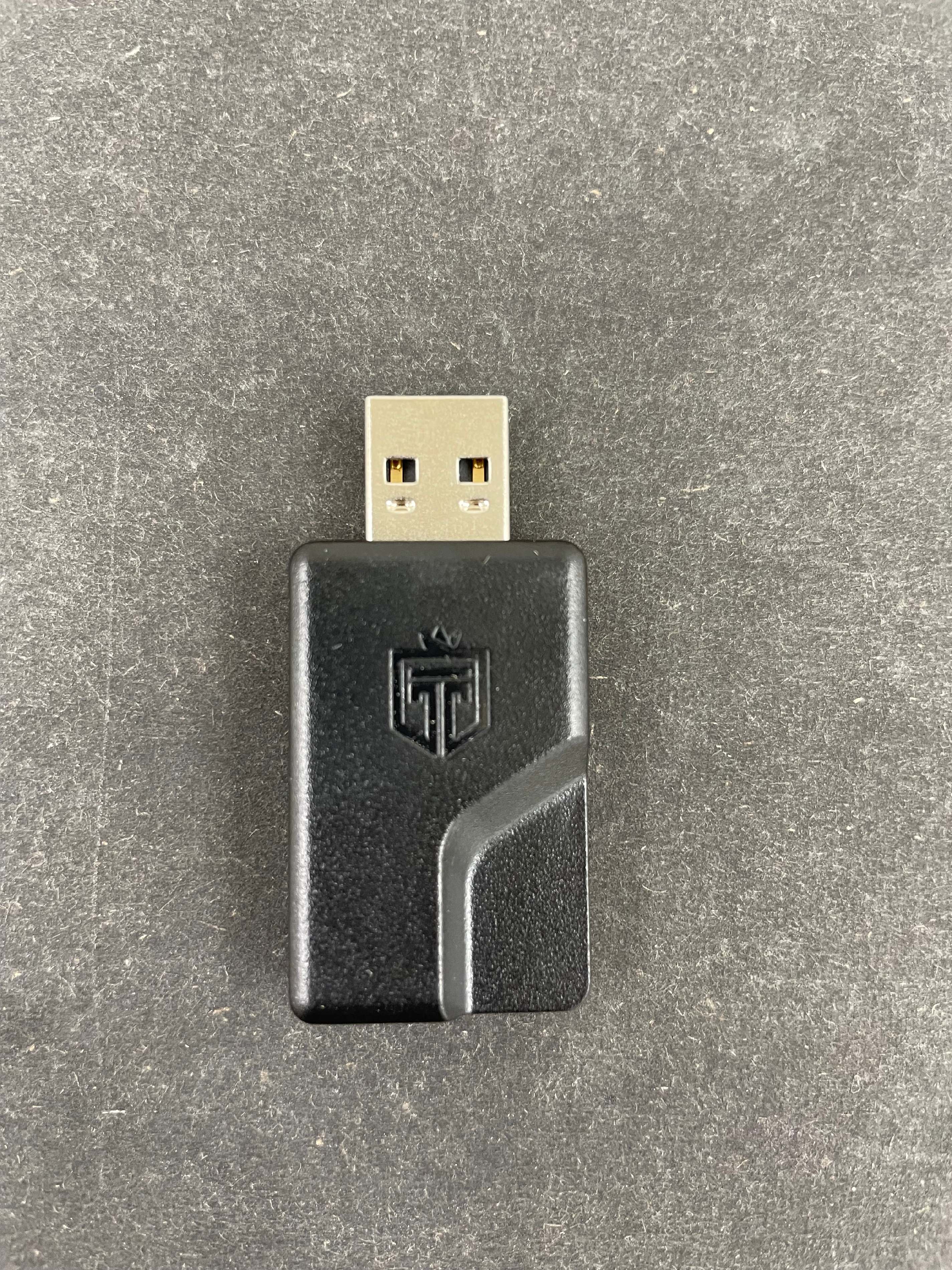
Digital Signal Transceiver for Entertainment System
Equipment Class
DTS - Digital Transmission System