2AKFQ100172.4 GHz & UHF (433-435 MHz) transceiver motion detector and GPS receiver
Cognosos, Inc.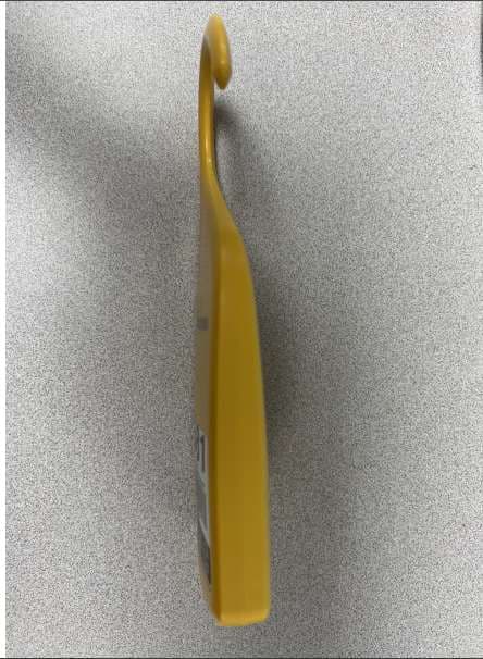
Click to zoom
Application Details
- Equipment Class
- DSC - Part 15 Security/Remote Control Transmitter
- Date of Grant
- Apr 13, 2022
- Application Purpose
- Original Equipment
- Date of Application
- Apr 13, 2022
- Equipment Note
- 2.4 GHz & UHF (433-435 MHz) transceiver motion detector and GPS receiver
- Frequency Range
- 433.16400000 - 435.32400000
- Company
- Cognosos, Inc.
- Country
- United States
Documents & Files
Document Text
Text extracted from the exhibit documents filed with the FCC. Open a document above to read the original.
Users Manual
Cognosos PCA-10017 Radio Module User’s Manual The PCA-10017 Radio Module is a small, battery powered 433MHz UHF and 2.4GHz BLE transceiver with integrated sensors. This module is extremely low power and is used to create end devices that operate on Cognosos’ radio networks. The baseline application for the end products includes asset tracking and sensor network applications. In use, a combination of events trigger the module to gather and relay sensor data to a Cognosos’ radio network. The PCA-10017 module communicates over a long-range UHF waveform. The BLE radio provides short range, higher data rate communication. Each communication mode is internally limited for compliance with the associated FCC/IC regulations. The end application may use the various transmission methods to communicate operational events, provide event-based alerts, assist device localization, or for system interrogation and maintenance. The Radio Module also contains an L1 GPS receiver with SAW and LNA on board. The GPS receiver is used for localization information. Product Models: For compatibility with multiple end-product designs, the PCA-10017 module comes in several variants, with the only difference being the direction the LEDs face or population of the optional serial port connector. Contact Cognosos at www.cognosos.com for more detailed information. Operational Modes Tracker Tag – This is the default mode of the PCA-10017. The tag is highly configurable with use case profiles. Profiles change device operation within regulatory requirements. Typically, profiles are used to enable or disable certain behaviors and reported data related to motion. As per FCC rules, devices only send UHF data with physical user interaction. Storage Mode – The PCA-10017 in tracker tag mode will sleep if the device is in the storage mode orientation. This orientation is dictated by the profile configuration. This mode is useful for transport and storage to minimize battery life. BLE Activator Mode – The PCA-10017 can act as a ‘BLE Activator’. In this mode, a configurable BLE advertisement will be sent per the BLE specifications. This activator is meant to provide contextual information to another PCA-10017 to aid with asset localization. Rev 2 System Operation A system comprises of multiple PCA-10017’s. An end-product containing a PCA-10017 will be installed onto an asset that is desired to be tracked. A gateway device will receive UHF messages from PCA-10017’s to determine the location of that asset. Additional PCA-10017’s configured in activator mode will provide localization support and influence the packet data sent to the gateway. In some cases the activator message will contain enough contextual information to bypass the GPS sequence. Host Integration: The PCA-10017 module is always integrated into a host device. When connecting to a host device, the following connections are made: PCA-10017 Module Connections Rev 2 Power: To power the module, apply 2.0-3.6 VDC across the VDC input and ground terminals. The module is protected against reverse voltage connection. Energizer L91 batteries should be used. Mounting: Two size 4 screw holes are provided for module mounting. Antennas: All antennas are integrated on the PCA-10017 module. For maximum performance, care should be taken to avoid metal in the area of the antennas. FCC and IC Labeling Requirements: When the PCA-10017 module is used in a host product, the host product is required to display “Contains FCC ID: 2AKFQ10017” and “Contains IC: 22165-10017” respectively to comply with FCC and IC rules. These marking must be on the outside of the unit in 4-point font minimum. Regulatory Warning: Changes or modifications to this device not expressly approved by Cognosos Inc. could void the user's authority to operate the equipment. FCC ID: 2AKFQ10017 IC: 22165-10017 This equipment complies with the FCC RF radiation exposure limits set forth for an uncontrolled environment. This shall be installed and operated with a minimum separation distance of 20cm between the radiator and any part of the human body. THIS DEVICE COMPLIES WITH PART 15 OF THE FCC RULES. OPERATION IS SUBJECT TO THE FOLLOWING TWO CONDITIONS. (1) THIS DEVICE MAY NOT CAUSE HARMFUL INTERFERENCE, AND (2) THIS DEVICE MUST ACCEPT ANY INTERFERENCE RECEIVED, INCLUDING INTERFERENCE THAT MAY CAUSE UNDESIRED OPERATION. NOTE: This equipment has been tested and found to comply with the limits for a Class B digital device, pursuant to Part 15 of the FCC Rules. These limits are designed to provide reasonable protection against harmful interference in a residential installation. This equipment generates, uses, and can radiate radio frequency energy and, if not installed and used in accordance with the instructions, may cause harmful interference to radio communications. However, there is no guarantee that interference will not occur in a particular installation. If this equipment does cause harmful interference to radio or television reception, which can be determined by turning the equipment off and on, the user is encouraged to try to correct the interference by one or more of the following measures: Reorient or relocate the receiving antenna. Increase the separation between the equipment and receiver. Connect the equipment into an outlet on a circuit different from that to which the receiver is connected. Consult the dealer or an experienced radio/TV technician for help. Radio/broadcast products shall comply with the requirements to include required notices and/or statements to the user of the product for each unit of the product offered for sale. The required notices shall comply with the following requirements: •The notices shall be as specified in the applicable RSS regulation(s) to the product. Rev 2 •These notices shall be shown in a conspicuous location in the user manual for the product, or to be displayed on the product - variable formats are acceptable for providing the notices (i.e. in paper form, CD, DVD, or insert wit…
Text truncated - open the document above for the full version.
Cover Letter(s)
1100 Spring Street NW, Suite 300A Atlanta, GA 30309 AGENCY AGREEMENT Federal Communications Commission Date: 10/15/2018 P.O. Box 429 Columbia, MD 21045 Gentlemen: By signature below, we hereby appoint US Tech employees Sandi McEnery, Alan Ghasiani and George Yang to act as our agents with regard to all FCC equipment authorizations. This appointment will remain in effect until otherwise notified. I further certify by signature below that no party (per 47 CFR 1.2002(b)) to the application is subject to a denial of Federal benefits, including FCC benefits, pursuant to Section 5301 of the Anti-Drug Abuse Act of 1988, 21 U.S.C. 853(a). This appointment includes the authority to complete FCC Form 731 on our behalf and sign the application as an authorized agent. Name: Jim Stratigos Signature: Title: CTO Date: 10/15/2018
Cover Letter(s)
3505 Francis Circle Alpharetta, GA 30004 PH: 770-740-0717 www.ustech-lab.com Request for Confidentiality Date: February 23, 2022 Subject: Confidentiality Request for: FCC ID: 2AKFQ10017; IC: 22165-10017 Pursuant to FCC 47 CFR 0.457(d) and 0.459 and IC RSP-100 Issue 12, sections 12.4 and 6.4, the applicant requests that a part of the subject FCC application be held confidential. Type of Confidentiality Requested Exhibit Short Term Permanent Block Diagrams Short Term Permanent Operation Description/Theory of Operation Short Term Permanent Schematics Cognosos, Inc. has spent substantial effort in developing this product and it is one of the first of its kind in industry. Having the subject information easily available to "competition" would negate the advantage they have achieved by developing this product. Not protecting the details of the design will result in financial hardship. Permanent Confidentiality: The applicant requests the exhibits listed above as be permanently withheld from public review due to materials that contain trade secrets and proprietary information not customarily released to the public. Sincerely, __________________________ Sandi McEnery – Agent (Signature) (Print name/Title)
Cover Letter(s)
Page 1 of 2 February 23, 2022 Cognosos, Inc. Model(s): PCA-10017 FCC ID : 2AKFQ10017 is seeking FCC Authorization as a Single Modular transmitter / Single Limited Modular Approval (Please check one) The EUT meets the requirements for Single Modular approval / Single Limited Modular Approval (please check one) as detailed in KDB 996369. Compliance to each of the requirements is described below: Item Modular requirement Yes No Please provide a detailed explanation if the answer is “No.” 1 Have its own RF shielding x The radio has been tested and shown to meet the applicable requirements without having a shield in place. Valid hosts are Cognosos models RT-250 and RT-260 2 Have buffered modulation/data inputs (if such inputs are provided) x 3 The modular transmitter must have its own power supply regulation. x The radio module shall be installed in host products that will supply regulated voltage to the radio module. Valid hosts are Cognosos models RT-250 and RT-260 4 Meet the antenna requirements of section 15.203 x 5 Be tested in a stand-alone configuration, i.e., the antenna, AC or DC power and data input/output lines must be connected to the module but, the module must not be inside another case during testing. x 6 Be labeled with its own FCC ID number, and if the FCC ID is not visible when the module is installed inside another device, then the outside of the device into which the module is installed must also display a label referring to the enclosed module. x 7 The modular transmitter is manufactured so that the user can not influence the operation of the transmitter that will operate outside of the scope of the regulations. x 8 Address compliance with the Commission`s RF exposure limits in Sections 1.1310 and 2.1093. x Note: (1) LMA may be granted when one or more of the requirements in the table above cannot be demonstrated. LMA will also be issued in those instances where applicants can demonstrate that they will retain control over the final installation of the device, such that compliance of the end product is assured. In such cases, an operating condition on the LMA for the module must state that the module is only approved for use when installed in devices produced by a specific manufacturer. When LMA is sought, the application for equipment certification must specifically state how control of the end product into which the module will be installed, and will be maintained, such that full compliance of the end product is always ensured. (2) Please provide Clear and specific instructions describing the conditions, limitations and procedures for third-parties to use and/or integrate the module into a host device. (3) For non-Software Defined Radio transmitter modules where software is used to ensure compliance of the device, technical description of how such control is implemented to ensure prevention of third party modification must be provided (see KDB 594280). Page 2 of 2 Note 1: Compliance of a module in its final configuration is the responsibility of the applicant. A host device will not be considered certified if the instructions regarding antenna configuration provided in the original description, of one or more separately certified modules it contains, were not followed. Example: A separately certified low-power transceiver module using Bluetooth technology which is housed in a desktop computer, laptop or peripheral does not require the overall system to be recertified, if the desktop computer, laptop or peripheral, as a stand-alone unit, complies with all applicable technical standards. Sandi McEnery Agent, Cognosos, Inc. General Manager, US Tech 770-740-0717 [email protected]
External Photos
US Tech Test Report: FCC Part 15/IC RSS Certification FCC ID: 2AKFQ10017 IC: 22165-10017 Test Report Number: 21-0414 Issue Date: February 23, 2022 Customer: Cognosos, Inc. Model: PCA-10017 Page 1 of 6 EXTERNAL PHOTOGRAPHS Figure 1. Front of Host Device US Tech Test Report: FCC Part 15/IC RSS Certification FCC ID: 2AKFQ10017 IC: 22165-10017 Test Report Number: 21-0414 Issue Date: February 23, 2022 Customer: Cognosos, Inc. Model: PCA-10017 Page 2 of 6 Figure 2. Back of Host Device US Tech Test Report: FCC Part 15/IC RSS Certification FCC ID: 2AKFQ10017 IC: 22165-10017 Test Report Number: 21-0414 Issue Date: February 23, 2022 Customer: Cognosos, Inc. Model: PCA-10017 Page 3 of 6 Figure 3. Left Side of Host Device US Tech Test Report: FCC Part 15/IC RSS Certification FCC ID: 2AKFQ10017 IC: 22165-10017 Test Report Number: 21-0414 Issue Date: February 23, 2022 Customer: Cognosos, Inc. Model: PCA-10017 Page 4 of 6 Figure 4. Right Side of Host Device US Tech Test Report: FCC Part 15/IC RSS Certification FCC ID: 2AKFQ10017 IC: 22165-10017 Test Report Number: 21-0414 Issue Date: February 23, 2022 Customer: Cognosos, Inc. Model: PCA-10017 Page 5 of 6 Figure 5. Top of Host Device US Tech Test Report: FCC Part 15/IC RSS Certification FCC ID: 2AKFQ10017 IC: 22165-10017 Test Report Number: 21-0414 Issue Date: February 23, 2022 Customer: Cognosos, Inc. Model: PCA-10017 Page 6 of 6 Figure 6. Bottom of Host Device
ID Label/Location Info
Module Label The module label is on the silk screen of the PCB. M/N: PCA-10017 Sample Host Label 1 Sample Host Label 2 RT-260 The label is attached to the exterior of the product. This product is smaller than the palm of the hand, so the full FCC statement is not included. But it is included in the manual.
Internal Photos
US Tech Test Report: FCC Part 15 Certification/ RSS 210 FCC ID: 2AKFQ10017 IC: 22165-10017 Test Report Number: 21-0414 Issue Date: February 23, 2022 Customer: Cognosos, Inc. Model: PCA-10017 INTERNAL PHOTOGRAPHS Figure 1. PCB – Front US Tech Test Report: FCC Part 15 Certification/ RSS 210 FCC ID: 2AKFQ10017 IC: 22165-10017 Test Report Number: 21-0414 Issue Date: February 23, 2022 Customer: Cognosos, Inc. Model: PCA-10017 Figure 2. PCB – Back US Tech Test Report: FCC Part 15 Certification/ RSS 210 FCC ID: 2AKFQ10017 IC: 22165-10017 Test Report Number: 21-0414 Issue Date: February 23, 2022 Customer: Cognosos, Inc. Model: PCA-10017 Figure 3. Radio Circuit US Tech Test Report: FCC Part 15 Certification/ RSS 210 FCC ID: 2AKFQ10017 IC: 22165-10017 Test Report Number: 21-0414 Issue Date: February 23, 2022 Customer: Cognosos, Inc. Model: PCA-10017 Figure 4. EUT in Host
RF Exposure Info
US Tech Test Report: FCC Part 15 Certification/ RSS 210 FCC ID: 2AKFQ10017 IC: 22165-10017 Test Report Number: 21-0414 Issue Date: April 5, 2022 Customer: Cognosos, Inc. Model: PCA-10017 Page 1 of 4 Maximum Permissible Exposure to RF (MPE), CFR 1.1310 (e) The maximum exposure level to the public from the RF power of the EUT shall not exceed a power density, S as per the respective limits in Table 1 below, at a distance, d, of 20 cm (Mobile condition) from the EUT. TABLE 1—LIMITS FOR MAXIMUM PERMISSIBLE EXPOSURE (MPE) Frequency range (MHz) Electric field strength (V/m) Magnetic field strength (A/m) Power density (mW/cm 2 ) Averaging time (minutes) Limits for General Population/Uncontrolled Exposure 0.3-1.34 614 1.63 *100 30 1.34-30 824/f 2.19/f *180/f 2 30 30-300 27.5 0.073 0.2 30 300-1,500 f/1500 30 1,500-100,000 1.0 30 f = frequency in MHz * = Plane-wave equivalent power density Therefore, for: MPE for 433.164 MHz – 435.324 MHz: Limit: 0.29 mW/cm 2 Peak Power (dBuV/m @ 3m) = 79.26 dBuV/m = -15.99 dBm Peak Power (Watts) = 0.025 W Gain of Transmit Antenna = -0.65 dB i = 0.86 numeric d = Distance = 20 cm = 0.2 m S = (PG/ 4π ππ πd 2 ) = EIRP/4A = 0.025 (0.86)/4*π*0.2*0.2 = 0.0215/0.5030 = 0.0427 W/m 2 = (0.0427 W/m 2 ) (1m 2 /W) (0.1 mW/cm 2 ) = 0.00427 mW/cm 2 which is << less than S = 0.29 mW/cm 2 US Tech Test Report: FCC Part 15 Certification/ RSS 210 FCC ID: 2AKFQ10017 IC: 22165-10017 Test Report Number: 21-0414 Issue Date: April 5, 2022 Customer: Cognosos, Inc. Model: PCA-10017 Page 2 of 4 MPE for 2400 MHz – 2483.5 MHz for WiFi: Limit: 1.0 mW/cm 2 Peak Power (dBm) = 14.0 dBm Peak Power (Watts) = 0.025 W Gain of Transmit Antenna = 4.7 dB i = 2.95 numeric(Highest Gain Antenna) d = Distance = 20 cm = 0.2 m S = (PG/ 4π ππ πd 2 ) = EIRP/4A = 0.025(2.95)/4*π*0.2*0.2 = 0.0738/0.5030 = 0.1466 W/m 2 = (0.1466 W/m 2 ) (1m 2 /W) (0.1 mW/cm 2 ) = 0.01466 mW/cm 2 which is << less than S = 1.0 mW/cm 2 US Tech Test Report: FCC Part 15 Certification/ RSS 210 FCC ID: 2AKFQ10017 IC: 22165-10017 Test Report Number: 21-0414 Issue Date: April 5, 2022 Customer: Cognosos, Inc. Model: PCA-10017 Page 3 of 4 RSS-102, 2.5.2 compliance for 433.164 MHz – 435.324 MHz: At or above 300 MHz and below 6 GHz and the source-based, time-averaged maximum e.i.r.p. of the device is equal to or less than 1.31 x 10 -2 ƒ 0.6834 W (adjusted for tune-up tolerance), where ƒ is in MHz; In this case ƒ = 434.244 MHz 1.31 * 10 -2 * 434.244 0.6834 = 0.83 W EUT max EIRP = -15.99 dBm + (-0.65 dBi) = -16.64 dBm EIRP = 0.022 mW Which is << than 830 mW RSS-102, 2.5.2 compliance for 2400 MHz – 2483.5 MHz: Limit= 1.31 x 10 -2 x 2440 0.6834 = 2.7 Watts Max EIRP for WiFi = 14.0 dBm + 4.7 dBi = 18.7 dBm = 74.13 mW << 2700 mW All calculations performed by: Date: 4/11/2022 Test Engineer: George Yang Signature:____________________ US Tech Test Report: FCC Part 15 Certification/ RSS 210 FCC ID: 2AKFQ10017 IC: 22165-10017 Test Report Number: 21-0414 Issue Date: April 5, 2022 Customer: Cognosos, Inc. Model: PCA-10017 Page 4 of 4 Simultaneous Transmission Collocation considerations: Please either confirm that the transmitters operate standalone per KDB 447498 D01 v06 section 7.1 or, if the transmitters can transmit simultaneously, include the necessary calculations for simultaneous transmission per KDB 447498 D01 v06 section 7.2. Please either confirm that the transmitters operate standalone or, if the transmitters can transmit simultaneously, include the necessary calculations for simultaneous transmission per ISED RSS-102 issue 5 section 3.1.2. The Transmitters do simultaneously broadcast but not at the same frequency. The device has two radios on board, however each radio transmits in a separate frequency band either 433-435 MHz or 2400-2483.5 MHz. The radios also do not share a common antenna. Each radio broadcast from its own antenna. Calculations for simultaneous transmission per KDB 447498 D01 v06 section 7.2 is provided here to show that Simultaneous transmission MPE test exclusion applies since the sum of the MPE ratios for all simultaneously transmitting antennas incorporated in a host device is ≤ 1.0. Per ISED RSS-102 (I5) section 3.1.2 other recognized methods can be used to show compliance, therefore this method is used to show compliance to RSS-102. Total Sum of MPE: Sum of the total MPE for both frequency bands = 0.00427/0.29 mW/cm 2 + 0.01466/1.0 mW/cm 2 = 0.02866 which is << less than 1.0 The EUT was tested with both radio ON and active. The emissions generated with a single radio ON and active versus both radios ON and active did not produce additional unwanted spurious emissions or intermodulation that would require additional testing. The radios can be collocated as designed.
Test Report
Page 1 of 21 Application for Certification Per Title 47 USC Part 2, Subpart J, Equipment Authorization Procedures, Paragraph 2.907, Certification and Part 15, Subpart C, Intentional Radiators, Paragraph 15.231, Periodic Operation in the band 40.66 MHz to 40.70 MHz and above 70 MHz And Innovation, Science, and Economic Development Canada Certification Per ICRSS-Gen General Requirements for Radio Apparatus And RSS-210 License-Exempt Radio Apparatus: Category I Equipment For the Cognosos, Inc. Model: PCA-10017 UST Project: 21-0414b Issue Date: February 23, 2022 Number of Pages in this report: 21 3505 Francis Circle Alpharetta, GA 30004 PH: 770-740-0717 Fax: 770-740-1508 www.ustech-lab.com Page 2 of 21 I certify that I am authorized to sign for the test facility and that all of the statements in this report and in the Exhibits attached hereto are true and correct to the best of my knowledge and belief: US Tech (Agent Responsible For Test): By: Name: Alan Ghasiani Title: President – Consulting Engineer Date: February 23, 2022 This report shall not be reproduced except in full. This report may be copied in part only with the prior written approval of US Tech. The results contained in this report are subject to the adequacy and representative character of the sample provided. This report must not be used to claim product certification, approval, or endorsement by NVLAP, NIST or any agency of the Federal Government. 3505 Francis Circle Alpharetta, GA 30004 PH: 770-740-0717 Fax: 770-740-1508 www.ustech-lab.com US Tech Test Report: FCC Part 15/IC RSS Certification FCC ID: 2AKFQ10017 IC: 22165-10017 Test Report Number: 21-00414b Issue Date: February 23, 2022 Customer: Cognosos, Inc. Model: PCA-10017 Page 3 of 21 MEASUREMENT TECHNICAL REPORT Company Name: Cognosos, Inc Address: 1100 Spring St. NW #300A Atlanta, GA 30309 Model: PCA-10017 FCC ID: 2AKFQ10017 IC: 22165-10017 Date: February 23, 2022 This report concerns (check one): ☒ Original ☐ Class II Permissive Change Equipment type: 433-435 MHz UHF transceiver Technical Information: Radio Technology: Frequency of Operation (MHz): 433.164- 435.324 Output Power: 79.26 dBuV/m @ 3m Type of Modulation: 2-GFSK Data/Bit Rate (M)bps: 100 bps Antenna Gain (dB): -0.65 Software used to program EUT: Cognosos Telluride EUT firmware: vaha0.4.0 Power setting: power set to “4” Report prepared by: US Tech 3505 Francis Circle Alpharetta, GA 30004 PH : 770-740-0717 Fax : 770-740-1508 www.ustech-lab.com US Tech Test Report: FCC Part 15/IC RSS Certification FCC ID: 2AKFQ10017 IC: 22165-10017 Test Report Number: 21-00414b Issue Date: February 23, 2022 Customer: Cognosos, Inc. Model: PCA-10017 Page 4 of 21 Table of Contents Paragraph Title Page 1. General Information ................................................................................................. 6 1.1 Product Description ............................................................................................ 6 1.2 Characterization of Test Sample ........................................................................ 6 1.3 Related Submittal(s)/Grant(s)............................................................................. 6 2. Tests and Measurements ......................................................................................... 7 2.1 Configuration of Tested System ......................................................................... 7 2.2 Test Facility ........................................................................................................ 7 2.3 Test Equipment .................................................................................................. 7 2.4 EUT Antenna Description (FCC Sec. 15.203, RSS-Gen 6.7) ............................. 9 2.5 Modifications to Equipment ................................................................................ 9 2.6 Test Procedure ................................................................................................... 9 2.7 Compliance to CFR 15.231(a), RSS-210, A.1.1(a) Transmitter Activation/Deactivation .............................................................................................. 10 2.8 Field Strength of Fundamental (47 CFR 15.231(b), RSS-210, A.1.2(b)) .......... 12 2.9 Limits for Operation in the Band above 70 MHz (CFR15.231 (b), RSS-210, A.1.2(b)) ..................................................................................................................... 13 2.10 Power Line Conducted Emissions and Radiated Spurious Emissions ............. 16 2.12 Bandwidth of Fundamental (CFR15.231(c), RSS-210, A.1.3) ......................... 19 2.13 Measurement Uncertainty ................................................................................. 21 2.13.1 Conducted Emissions Measurement Uncertainty ....................................... 21 2.13.2 Radiated Emissions Measurement Uncertainty .......................................... 21 List of Figures Figure Title Page Figure 1. Block Diagram of Test Configuration .............................................................. 10 Figure 2. Deactivation per 15.231(a)(1), RSS-210, A.1.1(a) ......................................... 11 Figure 3. Occupied Bandwidth (20 dB BW) CH0 ........................................................... 19 Figure 4. Occupied Bandwidth (20 dB BW) CH19 ......................................................... 20 US Tech Test Report: FCC Part 15/IC RSS Certification FCC ID: 2AKFQ10017 IC: 22165-10017 Test Report Number: 21-00414b Issue Date: February 23, 2022 Customer: Cognosos, Inc. Model: PCA-10017 Page 5 of 21 List of Tables Tables Title Page Table 1. EUT and Peripherals .................................................................................................... 7 Table 2. Test Instruments ........................................................................................................... 8 Table 3. Antenna Description ........................................................................…
Text truncated - open the document above for the full version.
Test Setup Photos
US Tech Test Report: FCC Part 15 Certification/ RSS 210 FCC ID: 2AKFQ10017 IC: 22165-10017 Test Report Number: 21-0414 Issue Date: February 23, 2022 Customer: Cognosos, Inc. Model: PCA-10017 Page 1 of 7 TEST CONFIGURATION PHOTOGRAPHS Figure 1. Radiated Emissions Test Setup, BT Radio US Tech Test Report: FCC Part 15 Certification/ RSS 210 FCC ID: 2AKFQ10017 IC: 22165-10017 Test Report Number: 21-0414 Issue Date: February 23, 2022 Customer: Cognosos, Inc. Model: PCA-10017 Page 2 of 7 Figure 2. Radiated Emissions Test Setup, UHF (433-435 MHz) Radio US Tech Test Report: FCC Part 15 Certification/ RSS 210 FCC ID: 2AKFQ10017 IC: 22165-10017 Test Report Number: 21-0414 Issue Date: February 23, 2022 Customer: Cognosos, Inc. Model: PCA-10017 Page 3 of 7 Figure 3. Radiated Emissions Test Setup (9 kHz - 30 MHz) Note 1: The antenna setup is the same for both radio modes of operation. The EUT orthogonal position is changed depending on the radio mode of operation being evaluated, either BT or UHF. Note 2: For spurious emissions from 9 kHz to 25 GHz other than fundamental and harmonics, the BT radio mode of operation was used for final measurements since this mode was deemed to be the worst case operating mode for the EUT. Note 3: For co-location evaluations both radios were evaluated with one ON and the either in idle or receive mode. The radios are not designed to simultaneously broadcast. US Tech Test Report: FCC Part 15 Certification/ RSS 210 FCC ID: 2AKFQ10017 IC: 22165-10017 Test Report Number: 21-0414 Issue Date: February 23, 2022 Customer: Cognosos, Inc. Model: PCA-10017 Page 4 of 7 Figure 4. Radiated Emissions Test Setup (30 - 200 MHz) Note 1: The antenna setup is the same for both radio modes of operation. The EUT orthogonal position is changed depending on the radio mode of operation being evaluated, either BT or UHF. Note 2: For spurious emissions from 9 kHz to 25 GHz other than fundamental and harmonics, the BT radio mode of operation was used for final measurements since this mode was deemed to be the worst case operating mode for the EUT. Note 3: For co-location evaluations both radios were evaluated with one ON and the either in idle or receive mode. The radios are not designed to simultaneously broadcast. US Tech Test Report: FCC Part 15 Certification/ RSS 210 FCC ID: 2AKFQ10017 IC: 22165-10017 Test Report Number: 21-0414 Issue Date: February 23, 2022 Customer: Cognosos, Inc. Model: PCA-10017 Page 5 of 7 Figure 5. Radiated Emissions Test Setup (200 MHz - 1 GHz) Note 1: The antenna setup is the same for both radio modes of operation. The EUT orthogonal position is changed depending on the radio mode of operation being evaluated, either BT or UHF. Note 2: For spurious emissions from 9 kHz to 25 GHz other than fundamental and harmonics, the BT radio mode of operation was used for final measurements since this mode was deemed to be the worst case operating mode for the EUT. Note 3: For co-location evaluations both radios were evaluated with one ON and the either in idle or receive mode. The radios are not designed to simultaneously broadcast. US Tech Test Report: FCC Part 15 Certification/ RSS 210 FCC ID: 2AKFQ10017 IC: 22165-10017 Test Report Number: 21-0414 Issue Date: February 23, 2022 Customer: Cognosos, Inc. Model: PCA-10017 Page 6 of 7 Figure 6. Radiated Emissions Test Setup (1 GHz – 6 GHz) Note 1: The antenna setup is the same for both radio modes of operation. The EUT orthogonal position is changed depending on the radio mode of operation being evaluated, either BT or UHF. Note 2: For spurious emissions from 9 kHz to 25 GHz other than fundamental and harmonics, the BT radio mode of operation was used for final measurements since this mode was deemed to be the worst case operating mode for the EUT. Note 3: For co-location evaluations both radios were evaluated with one ON and the either in idle or receive mode. The radios are not designed to simultaneously broadcast. US Tech Test Report: FCC Part 15 Certification/ RSS 210 FCC ID: 2AKFQ10017 IC: 22165-10017 Test Report Number: 21-0414 Issue Date: February 23, 2022 Customer: Cognosos, Inc. Model: PCA-10017 Page 7 of 7 Figure 7. Radiated Emissions Test Setup (6 GHz – 25 GHz) Note 1: The antenna setup is the same for both radio modes of operation. The EUT orthogonal position is changed depending on the radio mode of operation being evaluated, either BT or UHF. Note 2: For spurious emissions from 9 kHz to 25 GHz other than fundamental and harmonics, the BT radio mode of operation was used for final measurements since this mode was deemed to be the worst case operating mode for the EUT. Note 3: For co-location evaluations both radios were evaluated with one ON and the either in idle or receive mode. The radios are not designed to simultaneously broadcast. Note 4: The antenna is pulled into 1 meter test distance for measurements above 6 GHz. An inverse extrapolation factor is used to correct the measurement back to 3 meters. The anten…
Text truncated - open the document above for the full version.
Contact Information
Applicant
James Stratigos(CTO)
Test Firm
US TechGeorge Yang
Technical Specifications
| # | Rule Parts | Frequency Range | Power Output |
|---|---|---|---|
| 1 | 15.231 | 433.164 MHz - 435.324 MHz | - |
Other Applications from Cognosos, Inc.
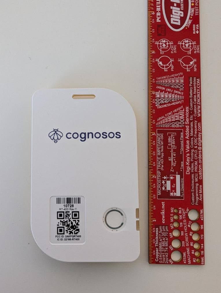
2AKFQRT400
Dec 01, 2024Wearable
Equipment Class
DSS - Part 15 Spread Spectrum Transmitter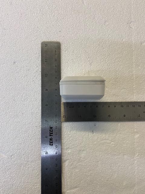
2AKFQ-RB300
Apr 12, 2021Low energy device used for asset tracking.
Equipment Class
DXX - Part 15 Low Power Communication Device Transmitter