2AKLX-10873A20-Nexus
Sound Devices, LLC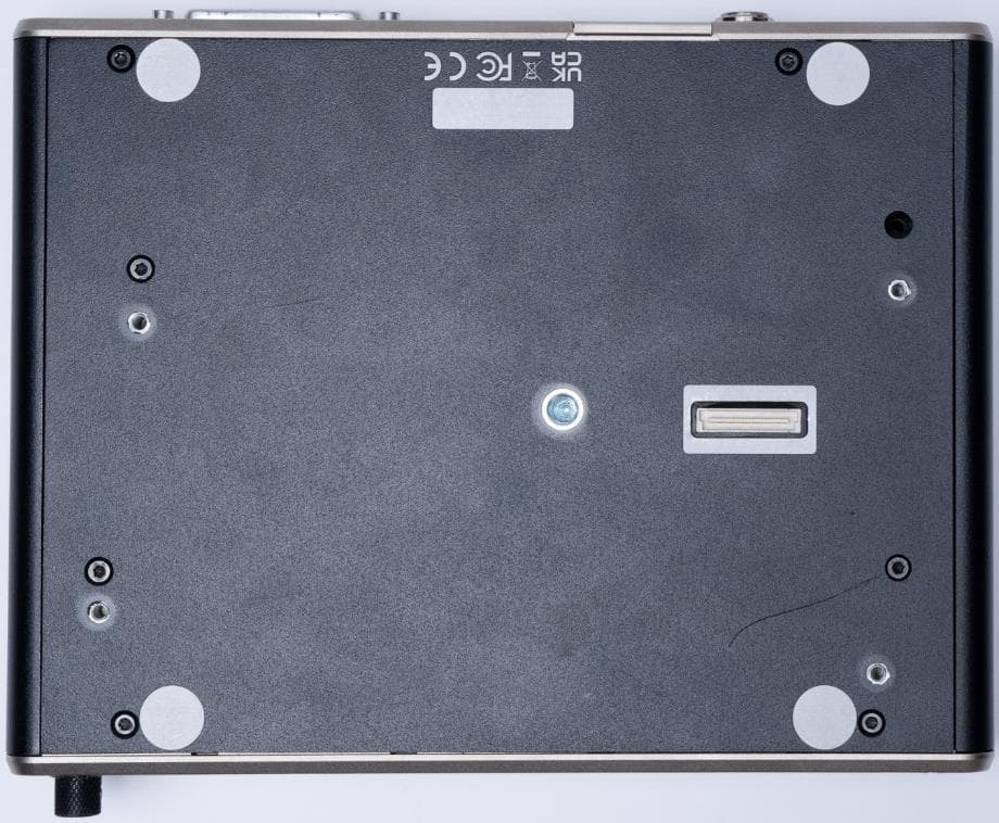
Click to zoom
Application Details
- Equipment Class
- DTS - Digital Transmission System
- Date of Grant
- May 01, 2023
- Application Purpose
- Original Equipment
- Date of Application
- Apr 13, 2023
- Equipment Note
- A20-Nexus
- Frequency Range
- 2402.00000000 - 2480.00000000
- Company
- Sound Devices, LLC
- Country
- United States
Documents & Files
Document Text
Text extracted from the exhibit documents filed with the FCC. Open a document above to read the original.
Users Manual
A20-Nexus 8-, 12-, and 16-Channel, True-Diversity Receiver with SpectraBand Technology User Guide v1.00 Table of Contents Welcome to the A20-Nexus4 Key Features4 SpectraBand5 Digital Wireless Modulation5 NexLink Wireless Transmitter Control5 GainForward5 Architectural Overview7 Panel Views8 Typical Setups12 Quick Start16 Powering19 Navigating the A20-Nexus User Interface21 Menus28 RTSA (Real Time Spectrum Analyzer)29 Scan Mode32 TX List33 RF Menu34 Antenna RF Overload Indication36 Audio Outputs36 Timecode39 Networking40 System Menu42 Quick Setup Menu45 Nexus Web App47 Updating Firmware50 Accessories51 A20-QuickDock for 8-Series51 A20-Monarch Antenna56 A20-Shelf56 2.4 GHz Antenna Bracket Assembly Kit56 Frequency Band Restrictions58 Connector Pin Assignments59 A20-NexusUser Guide 2 A20-Nexus Specifications61 A20-Monarch Specifications63 Note on RF Interference64 Servicing the A20-Nexus64 Warranty64 Legal Notices65 Declaration of Conformity68 A20-NexusUser Guide 3 Welcome to the A20-Nexus The A20-Nexus is an ultra-high performance, 8-, 12-, and 16-channel wireless microphone receiver in a compact ½-rack wide chassis. It features 8 independent, true-diversity channels which can be expanded to 12 or 16 true-diversity channels via software license. The A20-Nexus features NexLink, an innovative concept in wireless microphone receivers: full remote control of microphone transmitters via an integrated, long distance RF link. The A20-Nexus can be mounted in a standard 19-inch rack or easily placed remotely near the microphone transmitters due to its ability to be powered by Power-over-Ethernet (PoE+), its Dante audio-over-IP, and built-in web server for control via phone, tablet, or computer. Additionally, the A20-Nexus can be docked to Sound Devices 833, 888, or Scorpio mixer-recorders using the A20-QuickDock accessory, which provides convenient power, audio, and timecode connections with no additional cables. This accessory allows the A20-Nexus to connect and disconnect from the 833, 888, or Scorpio in seconds with no tools, and be remote mounted when desired. Key Features ●8-channel ultra-high-performance, true-diversity receivers in a ½ rack size (8.0” x 6.6” x 1.6”). ●Expandable to 12 or 16 channels via software license (coming soon). ●470 MHz – 1525 MHz tuning range via SpectraBand Technology. ●NexLink: integrated, long distance remote control of all wireless transmitters ●Dante audio-over-IP of RF receiver audio. ●Flexible powering: via PoE+, DC input, 8-Series, or AC mains (with optional adapter). ●Web App control from browser on any computer, smartphone or tablet. ●Full remote operation capability: Power via PoE, audio via Dante, control via Web App. ●Dual DB-25 connectors for 16 channels of mic, line, or AES outputs. ●Convert 16 channels of Dante to analog & AES on DB25 connectors for sending IFB, VOG & more from mixer to set. ●Wide, 6.2” color OLED array with touch for control and monitoring. ●Integrated Real Time Spectrum Analyzer (RTSA) and scanning for intuitive frequency coordination. ●Optical Fiber Network option via SFP slot. SFP accepts a wide variety of modular network transceivers. ●A20-QuickDock allows docking and undocking in seconds from 8-Series mixer-recorders with no tools. ●Supports GainForward Architecture: No gain setting on the A20-Mini transmitter. Adjust gain at the receiver or mixer. ●100% digital long-range modulation delivers the longest transmission distance of any digital system on the market. ●RF SAW filters for excellent rejection of interference from nearby IFB or camera hop transmitters. ●Excellent audio quality, full 10 Hz – 20 kHz audio bandwidth. ●BNC timecode input for auto timecode sync of transmitters over NexLink ●Front panel and rear panel BNC antenna inputs. Compatible with passive, bias-powered, and smart antennas. ●Cascade out option on rear BNCs for cascading multiple A20-Nexus units. ●Front-panel headphone output. ●USB-A port for thumb drives, keyboards, transmitter pairing, and timecode syncing. Supports USB hubs. Our friendly and knowledgeable support team, based in the USA and the UK, is here for all your questions and comments. A20-NexusUser Guide 4 SpectraBand The A20-Nexus incorporates SpectraBand, a technology that enables the A20-Nexus to tune over a super wide range of 470-1525 MHz. Tuning within this range varies by country. For instance: In the USA, the available frequency ranges are: ●The entire UHF TV band (470-608 MHz) ●The 600 MHz guard band (614-616 MHz) ●The 600 MHz duplex gap (653-663 MHz) ●The 900 MHz ISM Band (902-928MHz) ●The 950 MHz STL Band (941.5-960 MHz) ●The 1.5 GHz AFTRCC band (1435-1525 MHz), with an appropriate license. In the UK, the available frequency ranges are: ●The core UK UHF TV band (470-702 MHz) ●The 800 MHz duplex gap (823-832 MHz) ●The 800 MHz guard band (863-865 MHz) ●The DME bands (961-1015 MHz, 1045-1075 MHz, 1105-1154 MHz), with an appropriate license. ●The IMT band (1518-1525 MHz) Please seehttps://www.sounddevices.com/frequency-tables/for further detailed information on which frequency ranges are available for each country. Tuning Bands SpectraBand’s 470-1525 MHz range is divided into multiple, tightly-filtered tuning bands. The sharp attenuation at either end of a tuning band’s range significantly reduces out of band interference resulting in excellent range performance. Digital Wireless Modulation Long Range and Standard Modulation The A20 wireless products offer two proprietary digital modulation schemes that provide unbeatable range, unrivaled audio quality, and very low latency. Long Range or Standard modulation can be selected on a per-receiver-channel basis. Long Range modulation has better sensitivity which results in better range. The modulation setting must match between the A20-Mini, A10-TX and the A20-Nexus in order for the transmitted signal to be received and decoded. Intermodulation Immunity Because the A20 and A10 digital RF transmission is inherently resistant to intermodulation, mu…
Text truncated - open the document above for the full version.
Users Manual
KDB353028 D01 II A (2) (c) - Antenna Requirements {15.203} The applicant should address the following items when justifying professional installation: (1) Explain why the hardware is not readily available to average consumer. The A20-Nexus is a multi-channel wireless microphone receiver marketed and sold only to commercial sound companies and installed by professional sound engineers. There are several factors which support this: • Selling price of A20-Nexus plus transmitting equipment is approximately $32,000 per system. Only top tier companies who use these products professionally purchase a system of this type. For comparison, a typical consumer-type wireless microphone system would cost less than $1,000. • The A20-Nexus is not in any way marketed to the average consumer. • The A20-Nexus is not sold via general consumer stores or websites. (2) Confirm the device cannot be sold via retail to the general public or by mail order; it must be sold to authorized dealers or installers only. • The A20-Nexus is sold only to authorized dealers and is not available via mail-order or to the general public. (3) Explain that intended use is not for consumers and general public; rather device is generally for industrial/commercial use. • The A20-Nexus is used by professional sound engineers. Examples include recording sound for major motion pictures, major concerts/events, and large broadcast television productions like the Olympics. This is squarely outside of the realm of consumers and consumer audio products. (4) Explain what is unique, sophisticated, complex, or specialized about the equipment that REQUIRES it to be installed by a professional installer? • Deploying an A20-Nexus system requires an installation by a professional sound engineer who is well-versed in RF theory and practical use of professional wireless audio systems. Installers will generally have Part 74 licenses. System commissioning requires finding clear spectrum and performing frequency coordination to avoid intermodulation from multiple transmitters. A20-Nexus installers must be familiar with these practices – this is far outside the understanding of a typical consumer. iv) Other professional installation requirements. (1) Installation must be controlled – explain how. • The installation of the A20-Nexus is generally done by the same professional sound engineer who operates the system. (2) Installed by licensed professionals (e.g., device sold to dealer who hire installers) – confirm details. • The professional sound engineer who installs this system will generally have a Part 74 license (3) Installation requires special training (e.g., special programming, access to keypad, field strength measurements made). Confirm details. • In addition to a Part 74 license, the professional sound engineer who installs this system will generally have received specialized training in spectrum management and frequency coordination.
Attestation Statements
P O R T A B L E , P R O F E S S I O N A L A U D I O Doc nr. Certification Application Attestation Statements Company name: Sound Devices, LLC Address: P.O. Box 576, E7556 State Road 23 and 33 City: Reedsburg, WI 53959 Country: United States of America Subject: FCC ID: 2AKLX-10873 To Whom It May Concern: Statement for 47 CFR section 2.911(d)(5)(i) Sound Devices, LLC certifies that as of the date of the application the equipment for which authorization is sought is not “covered” equipment 1 prohibited from receiving an equipment authorization pursuant to section 2.903 of the FCC rules. If the equipment for which the applicant seeks authorization is produced by any of the entities identified on the current Covered List, including affiliates or subsidiaries of the named companies, the applicant must include an explanation on why the equipment is not “covered” equipment. Additional Explanation: <N/A> Statement for 47 CFR section 2.911(d)(5)(ii) Sound Devices, LLC (“the applicant”) certifies that, as of the date of the filing of this application, the applicant - is / - is not (3) identified on the Covered List as an entity producing “covered” equipment. Date: 08/02/2023 City: Reedsburg Name (2) : Matthew Anderson Function: President and CEO Telephone number: (608) 524-0625 Email address: [email protected] Signature: 1 - The Commission’s Covered List is published by the Public Safety and Homeland Security Bureau and posted on the Commission’s website. This Covered List, which is periodically updated, identifies particular equipment, produced by particular entities, that constitutes “covered” equipment. https://www.fcc.gov/supplychain/coveredlist . (2): For FCC it must be the Grantee Code “owner” or the authorized agent. (3): double cllick on the appropriate box and select ‘’checked” then “OK”
Attestation Statements
POR TABLE, PROFESSIONAL AUDIO U.S. Agent Designation for Service of Process (Applicant is Both Grantee and U.S. Agent) TO: Kiwa Nederland B.V. Wilmersdorf 50 7327 AC Apeldoorn Postbus 137 7300 AC Apeldoorn Netherlands ATTENTION: FCC Certification – Section 2.911(d)(7) Information This letter is to confirm that the Applicant will also serve as the U.S. Agent for Service of Process as required by 47 CFR 2.911(d)(7). The Applicant acknowledges that they must maintain an agent for no less than one year after terminating all marketing and importation OR the conclusion of any Commission-related proceeding involving the equipment. The Applicant further acknowledges their responsibility to inform the FCC whenever the Designated U.S. Agent information changes. Applicant Company name: Sound Devices, LLC Grantee Code: 2AKLX Contact person name: Matthew Anderson Street address: E7556 State Road 23 and 33, P.O.BOX: 576 ZIP/City/State Reedsburg Telephone number: (608) 524-0625 Email address: [email protected] Signature: Date: Februar y 08, 2023 Note *Must be signed by both the applicant, and agent on behalf
Cover Letter(s)
P O R T A B L E , P R O F E S S I O N A L A U D I O Declaration of Authorization We Name: Sound Devices, LLC Address: P.O.Box 576, E7556 State Road 23 and 33 City: Reedsburg, WI 53959 Country: United States of America Declare that: Name Representative of agent: Daniel Sims Agent Company name: RN Electronics Ltd Address: Arnolds Court, Arnolds Farm Lane City: Mountnessing, Brentwood Country: UK is authorized to apply for Certification of the following product(s): Product description: A20-Nexus Type designation: 10873 Trademark: Sound Devices Validity/ expiry date: 07-11-2022 / 07-11-2023 on our behalf. Date: November 7, 2022 City: Reedsburg Name: Matthew Anderson Function: President and CEO Signature: RF_160, Issue 04
Cover Letter(s)
FCC, Request for non-disclosure Date: 21-Nov-2018 RF_501, Issue 8 Page 1 of 1 Company Name: Sound Devices, LLC Address: P.O.Box 576, E7556 State Road 23 and 33 City: Reedsburg, WI 53959 Country: United States of America To: Telefication B.V., Dept. FCC TCB Edisonstraat 12A 6902 PK ZEVENAAR The Netherlands Subject: Request for confidentiality FCC ID: 2AKLX-10873 Reference number: Dear FCC TCB, 1. Long-Term Confidentiality Pursuant to 47 CFR Section 0.459(a) & (b), we hereby request non-disclosure and confidential treatment of the following materials submitted in support of FCC certification application: Bill(s) of Material Block Diagrams Operational Description Schematic Diagrams Tune-up Procedure Above materials contain secrets, proprietary and technical information, which would customarily be guarded from competitors under 47 CFR, section 0.457(d)(2). Disclosure or publication or any portion of this company confidential material to other parties could cause substantial competitive harm and provide unjustified benefits for competitors. 2. Short-Term Confidentiality (STC) Pursuant to Public Notice DA 04-1705 of the Commission’s policy, in order to comply with the marketing regulations in 47 CFR §2.803 and the importation rules in 47 CFR §2.1204, a pplicant hereby requests Short-Term Confidential treatment of the following materials (See notes below): Internal Photos User’s Manual Test Set-up Photos External Photos Justification: Date: November 7, 2022 Name and signature of applicant: Matthew Anderson Matthew Anderson
Cover Letter(s)
RN_FCC_001, Issue 01 Declaration of Non-Denial of federal benefits & acceptance of grantee responsibilities We Name: Sound Devices, LLC Address: P.O.Box 576, E7556 State Road 23 and 33 City: Reedsburg, WI 53959 Country: United States of America certify that we are not subject to denial of federal benefits, that includes FCC benefits, pursuant to Section 5301 of the Anti-Drug Abuse Act of 1988, 21 U.S.C. 862. Further, no party, as defined in 47 CFR 1.2002 (b), to the application is subject to denial of federal benefits, that includes FCC benefits. We also declare that the information provided to the FCC is true and correct to the best of our knowledge (47 CFR 2.911(d)) and we have been informed of the grantee responsibilities (47 CFR 2.909) with regard to certified equipment. Date: November 7, 2022 Name: Matthew Anderson Function: President and CEO Signature:
External Photos
Page 1 of 3 External Photographs Device Model Name: A20-Nexus Device Model Number: 10873 Manufacturer: Sound Devices, LLC FRONT VIEW TOP VIEW Page 2 of 3 BOTTOM VIEW RIGHT SIDE VIEW Page 3 of 3 LEFT SIDE VIEW REAR VIEW 2.4G ANTENNAS ATTACHED
ID Label/Location Info
Page 1 of 2 ID Label and Location Device Model Name: A20-Nexus Device Model Number: 10873 Manufacturer: Sound Devices, LLC 1- ELECTRONIC LABELING IMPLEMENTED (KDB 784748 D02) Three steps are required to access regulatory information (FCC ID, etc) from Main Menu via Touch-Screen OLED: SCREENSHOT ‘Main Menu’ (1) Select ‘System’ button >> SCREENSHOT ‘System Menu 1/2' (2) Select ‘More ...’ button >> SCREENSHOT ‘System Menu 2/2' (3) Select ‘Legal/Patent’ button >> Page 2 of 2 SCREENSHOT ‘Legal/Patent Information’ 2- TEMPORARY PACKAGING LABEL IMPLEMENTED (KDB 784748 D01) A stick-on label is attached to the product packaging for identification purposes at the time of importation, marketing, and sales to comply with the FCC’s equipment authorization requirements. A drawing of label is shown below. The font is Helvetica size 7 pt.
RF Exposure Info
Arnolds Court, Arnolds Farm Lane, Mountnessing, Brentwood, Essex, CM13 1UT Registered in England No. 3051259 Registered Office: Kiwa House, Malvern View Business Park, Stella Way, Bishops Cleeve, Cheltenham, GL52 7DQ. T: +44 1277 352219 E: [email protected] FCC & ISED RF Exposure technical brief Product/Client information: EUT Name: A20-Nexus EUT Model: 10873 Applicant: Sound Devices LLC Address: E7556 State Road 23 and 33 Reedsburg, Wisconsin 53959 USA FCC ID: 2AKLX-10873 IC ID: 22225-10873 Product Description: The A20-Nexus is a multi-channel wireless microphone receiver with a Bluetooth Low Energy and a Proprietary long range 2.4GHz FHSS Transmitter. The device is a mobile device that is used in professional program making and special events applications. As such RF exposure distance can be controlled by installation. For the purposes of this exclusion calculation a distance of 200mm has been declared as the worst case, and the power used is either the maximum field strength measured from the device, or maximum conducted power measured of the device. The Bluetooth LE operates using a low channel of 2402 MHz and a High channel of 2480 MHz and with a maximum declared duty cycle of 10%. The proprietary 2.4 GHz FHSS operates using 2400.8 MHz low channel and 2481.6 MHz High channel and with a maximum duty cycle declared of 20%. Each transmitter utilises the same two RF ports via RF switching. The two transmitters do not simultaneously transmit in operation, this is managed in the control software. Therefore, RF exposure is calculated for each transmitter operating individually using the following maximum powers stated from either port A or Port B, including tune up tolerance. Measured Power values. FHSS Proprietary 2.4GHz measured Peak radiated field strength: Low channel 105.9 dBuV/m @3m (Port A) = 10.7 dBm / 11.75 mW Mid channel 105.7 dBuV/m @3m (Port A) = 10.5 dBm / 11.22 mW High channel 106.7 dBuV/m @3m (Port A) = 11.5 dBm / 14.13 mW FHSS Proprietary 2.4GHz measured Peak Conducted Power: Low channel 7.04 dBm (Port A) Mid channel 6.67 dBm (Port A) High channel 7.29 dBm (Port A) Bluetooth Low Energy 2.4GHz measured Peak radiated field strength: Low channel 100.3 dBuV/m @3m (Port B) = 5.1 dBm / 3.24 mW Mid channel 101.8 dBuV/m @3m (Port B) = 6.6 dBm / 4.57 mW High channel 99.8 dBuV/m @3m (Port B) = 4.6 dBm / 2.88 mW Bluetooth Low Energy 2.4GHz measured Peak Conducted Power: Low channel 4.24 dBm (Port B) Mid channel 4.86 dBm (Port B) High channel 3.70 dBm (Port B) Arnolds Court, Arnolds Farm Lane, Mountnessing, Brentwood, Essex, CM13 1UT Registered in England No. 3051259 Registered Office: Kiwa House, Malvern View Business Park, Stella Way, Bishops Cleeve, Cheltenham, GL52 7DQ. T: +44 1277 352219 E: [email protected] FCC RF Exposure. FCC Evaluation is for exposure potential against the Exclusion limits given in KDB447498 D01 v06 section 4.3.1. Exclusion requirements are based upon 10g SAR exclusion for extremities. Proprietary 2.4GHz transmitter: Equation of 4.3.1. part 1A Transposed is: Exclusion in mW = ((Threshold / (√F)) * D) where: Threshold = 7.5 for 10g SAR Extremities F = Frequency in GHz (2.4008 GHz) & (2.4408 GHz) & (2.4816 GHz) D = Separation distance in mm (200mm) Threshold in mW for 2400.8 MHz = 242.021 mW (power allowed at numeric threshold for 50mm) (step a) Threshold in mW for 2440.8 MHz = 240.029 mW (power allowed at numeric threshold for 50mm) (step a) Threshold in mW for 2481.6 MHz = 238.048 mW (power allowed at numeric threshold for 50mm) (step a) Based on channel results above and KDB447498 D01 v06 4.3.1. part b)2): B2) {[Power allowed at numeric threshold for 50 mm in step a)] + [(test separation distance – 50 mm * 10) mW, for >1500 MHz and <6 GHz frequency range. (Using channel frequencies above and separation distance of 200mm) we have = 242.021mW+ (200mm-50mm * 10) = 240.029 mW+ (200mm-50mm * 10) = 238.048 mW+ (200mm-50mm * 10) Therefore, exclusion for Proprietary 2.4 GHz transmitter per channel at 200mm distance is: Low channel 2400.8 MHz = 1742 mW. Mid channel 2440.8 MHz = 1740 mW. Top channel 2481.6 MHz = 1738 mW. Measured maximum peak Radiated value for the EUT in Proprietary 2.4 GHz mode was: 106.7dBuV/m @ 3m (on high channel 2481.6 MHz) which is +11.5 dBm (or 14.13 mW). Adding 2dB for tune up tolerance adjustment gives 13.5dBm / 22.38mW worst case. Antenna gain is included in the field strength measurements. These figures are for a 100% Transmit EUT Duty cycle. Measured maximum Peak Conducted power was 7.29dBm (5.36 mW) Adding 2dB for tune up tolerance adjustment gives 9.29dBm / 8.49 mW worst case. These figures are for a 100% Transmit EUT Duty cycle. Maximum Declared duty cycle for proprietary 2.4GHz transmitter operation is 20% and as such, time averaged power would be much lower, however for the purpose of this calculation a 100% duty cycle is used. Based on the above the EUT in proprietary 2.4GHz mode is excluded from FCC RF Exposure / SAR testing requirements. Arnolds Court, Arnolds Farm Lane, Mountnessing, Brentwood, Essex, CM13 1UT Registered in England No. 3051259 Registered Office: Kiwa House, Malvern View Business Park, Stella Way, Bishops Cleeve, Cheltenham, GL52 7DQ. T: +44 1277 352219 E: [email protected] Bluetooth 2.4GHz transmitter: Equation of 4.3.1. part 1A Transposed is: Exclusion in mW = ((Threshold / (√F)) * D) where: Threshold = 7.5 for 10g SAR Extremities F = Frequency in GHz (2.402 GHz) & (2.440 GHz) & (2.480 GHz) D = Separation distance in mm (200mm) Threshold in mW for 2402MHz = 241.960 mW (power allowed at numeric threshold for 50mm) (step a) Threshold in mW for 2440 MHz = 240.069 mW (power allowed at numeric threshold for 50mm) (step a) Threshold in mW for 2480 MHz = 238.125 mW (power allowed at numeric threshold for 50mm) (step a) Based on channel results above and KDB447498 D01 v06 4.3.1. part b)2): B2) {[Power allowed at numeric threshold for 50 mm in step a)] + [(test separation distance – 50 mm * 1…
Text truncated - open the document above for the full version.
Test Report
Wireless External Antenna for 2.4 GHz Application Pulse Part Number: W1010 © 2014. All Rights Reserved. Pulse Finland Oy Takatie 6 90440 Kempele, Finland Tel: +358 207 935 500 Fax: +358 207 935 501 www.pulselectronics.com/products/antennas LxxxA (xx/xx) Features - Shortest antennas in product line Omnidirectional radiation - For WLAN devices using WiFi (802.11b/g), Bluetooth®, ZigBee™ and other applications in the ISM 2.4GHz band - Omnidirectional radiation pattern provides broad 360° coverage - One-quarter wavelength dipole configuration - Connection and color options easily integrate with OEM designs Connector - SMA (Male) Weight 6.3 grams Carton 20/bag; 500/carton Dimensions: Unless otherwise specified, all tolerances are ± Electrical Specifications @ +25 °C Note: This part number is lead-free and RoHS compliant. No additional suffix or identifier is required. Inches mm 0.10 0.25 3.255 1.017 .019 25.85 .50 .039 82.7 1 Frequency [GHz] Gain [dBi] Impedance [Nom] VSWRPolarization Electrical Length Radiation 2.4 – 2.5 2.050 Ω≤ 2.0Vertical 1/4, di- pole Omni Wireless External Antenna for 2.4 GHz Application Pulse Part Number: W1010 © 2014. All Rights Reserved. Pulse Finland Oy Takatie 6 90440 Kempele, Finland Tel: +358 207 935 500 Fax: +358 207 935 501 www.pulselectronics.com/products/antennas LxxxA (xx/xx) Application Notes Omni-directional antennas provide a uniform, donut- shaped, 360° radiation pattern. The omni-directional pattern is suitable for point-to-multipoint broadcast- ing in all directions. This antenna is primarily used for WLAN applications. However, it can also be used for a variety of other applications withing the spec ified frequency range. When used as an access point, the antenna is ideally located at the center of the coverage area. Gain Performance W1010 Vertical Position Horizontal Position
Test Report
Page 1 of 110 File Name: Sound Devices LLC.13348-13 Issue 01 QMF21J - Issue 05 - RNE Issue 03; 47 CFR Part 15C 2021 Radio Test Report Sound Devices LLC Multi-Channel Wireless Microphone Receiver A20-NEXUS 47 CFR Part 15.247 Effective Date 1st October 2021 DTS: Digital Transmission System Test Date: 28th September 2022 to 7th October 2022 Report Number: 10-13348-13-22 Issue 01 The testing was carried out by RN Electronics Ltd, an independent test house, at their test facility located at: R.N. Electronics Ltd. Arnolds Court Arnolds Farm Lane Mountnessing Essex CM13 1UT U.K. www.RNelectronics.com Telephone: +44 (0) 1277 352219 Email: [email protected] This laboratory is accredited in accordance with the recognised International Standard ISO/IEC 17025. This accreditation demonstrates technical competence for a defined scope and the operation of a laboratory quality management system (refer joint ISO-ILAC-IAF communiqué dated April 2017). This report is not to be reproduced by any means except in full and in any case not without the written approval of R.N. Electronics Ltd. ©2022 RN ELECTRONICS LIMITED REPORT NUMBER: 10-13348-13-22 Issue 01 ALL RIGHTS RESERVED Page 2 of 110 File Name: Sound Devices LLC.13348-13 Issue 01 QMF21J - Issue 05 - RNE Issue 03; 47 CFR Part 15C 2021 Arnolds Court, Arnolds Farm Lane, Mountnessing, Brentwood Essex, CM13 1UT Certificate of Test 13348-13 The equipment noted below has been fully tested by R.N. Electronics Limited and, where appropriate, conforms to the relevant subpart of 47 CFR Part 15C. This is a certificate of test only and should not be confused with an equipment authorisation. Other standards may also apply. Equipment: Multi-Channel Wireless Microphone Receiver Model Number: A20-NEXUS Unique Serial Number: JY0022164000 Applicant: Sound Devices LLC PO Box 576 E7556 State Road 23-33 Reedsburg WI 53959 USA Proposed FCC ID 2AKLX-10873 Full measurement results are detailed in Report Number: 10-13348-13-22 Issue 01 Test Standards: 47 CFR Part 15.247 Effective Date 1st October 2021 DTS: Digital Transmission System DEVIATIONS: No deviations have been applied. Note: This report covers Bluetooth operation only. This certificate relates only to the unit tested as identified by a unique serial number and in the condition at the time it was tested. It does not relate to any other similar equipment and performance of the product before or after the test cannot be guaranteed. Whilst every effort is made to assure quality of testing, type tests are not exhaustive and although no non-conformances may be found, this doesn't exclude the possibility of unit not meeting the intentions of the standard or the requirements of the Federal Regulations, particularly under different conditions to those during testing. Any compliance statements are made reliant on (a) the application of the product and use of the assigned band being acceptable to the FCC and (b) the modes of operation as instructed to us by the Customer based on their specific knowledge of the application and functionality of the EUT. Statements of compliance, where measurements were made, do not include the measurement uncertainty. The measurement uncertainty, where stated, is the expanded uncertainty based on a standard uncertainty multiplied by a coverage factor of k=2, providing a level of confidence of approximately 95%. Date of Test: 28th September 2022 to 7th October 2022 Test Engineer: Chee-Wah Yeung Approved By: Radio Manager Customer Representative: ©2022 RN ELECTRONICS LIMITED REPORT NUMBER: 10-13348-13-22 Issue 01 ALL RIGHTS RESERVED Page 3 of 110 File Name: Sound Devices LLC.13348-13 Issue 01 QMF21J - Issue 05 - RNE Issue 03; 47 CFR Part 15C 2021 1 Contents 1 Contents .......................................................................................................................................................... 3 2 Equipment under test (EUT) ........................................................................................................................... 5 2.1 Equipment specification ......................................................................................................................... 5 2.2 Configurations for testing ....................................................................................................................... 6 2.3 Functional description ............................................................................................................................ 7 2.4 Modes of operation ................................................................................................................................. 7 2.5 Emissions configuration ......................................................................................................................... 8 3 Summary of test results ................................................................................................................................ 10 4 Specifications ................................................................................................................................................ 11 4.1 Relevant standards ................................................................................................................................ 11 4.2 Deviations ............................................................................................................................................... 11 4.3 Tests at extremes of temperature & voltage .......................................................................................... 11 5 Tests, methods and results ........................................................................................................................... 12 5.1 AC power line conducted emissions .................................................................................................... 12 5.2 Radiated emissions 9 - 150 kHz...............................................................................…
Text truncated - open the document above for the full version.
Test Setup Photos
1.1 AC Conducted emissions 0.15 - 30 MHz 1.2 Radiated emissions…
Text truncated - open the document above for the full version.
Contact Information
Applicant
Matthew Anderson(President and CEO)
Technical Contact
Audio LimitedLee Stone
[email protected]44 1494 511711
7 Century Court, Tolpits Lane · Watford · United States
Non-Technical Contact
Sound Devices, LLCMatthew Anderson
[email protected](608) 524-0625
Test Firm
Kiwa LtdClint Hilling
[email protected]44 1277 352219
Technical Specifications
| # | Rule Parts | Frequency Range | Power Output |
|---|---|---|---|
| 1 | 15C | 2.40 GHz - 2.48 GHz | 4.60 mW |
Other Applications from Sound Devices, LLC
2AKLX-28297
Mar 26, 2026Digital wireless handheld microphone transmitter
Equipment Class
TLD - Licensed LPAS Device
2AKLX-28303
Jul 30, 2024A20-SuperNexus
Equipment Class
DSS - Part 15 Spread Spectrum Transmitter
2AKLX-9295W
Nov 09, 2022A20-MINI
Equipment Class
DWM - Part 15 Wireless Microphone