2AKLX-9295WA20-MINI
Sound Devices, LLC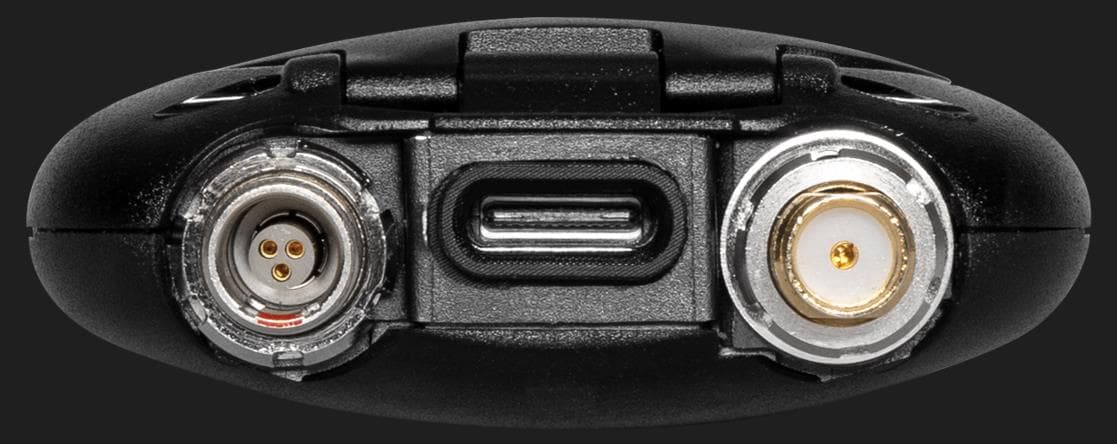
Click to zoom
Application Details
- Equipment Class
- DWM - Part 15 Wireless Microphone
- Date of Grant
- Nov 09, 2022
- Application Purpose
- Original Equipment
- Date of Application
- Nov 08, 2022
- Equipment Note
- A20-MINI
- Frequency Range
- 657.10000000 - 662.90000000
- Company
- Sound Devices, LLC
- Country
- United States
Documents & Files
Document Text
Text extracted from the exhibit documents filed with the FCC. Open a document above to read the original.
Users Manual
A20-Mini Digital Wireless Transmitter with GainForward and SpectraBand Technologies User Guide v6.00 Table of Contents Welcome to the A20-Mini 3 SpectraBand 4 Panel Views 4 Power 7 A20-Mini Holster 8 Introduction to A20-Remote 9 A20-Remote Overview 10 Manage Transmitters 13 Transmitter List 15 Transmitter View 19 Group Control 23 Group Setup 23 Group View 24 Connecting Lavalier Microphones to A20-Mini 28 Tuning A20-Mini and the Receiver 28 GainForward 28 Recording WAV Files 28 Jamming Timecode on A20-Mini 29 File Transfer to a Computer 29 Updating A20-Mini Firmware 30 SD-Utility 31 PowerStation-8M 34 PowerStation-8M Specifications 36 A20-Mini Specifications 37 Antenna Guide 39 Servicing the A20-Mini 40 Warranty 40 Included Accessories 40 Legal Notices 41 Declaration of Conformity 44 A20-Mini User Guide 2 Welcome to the A20-Mini Sound Devices’ first miniature transmitter incorporates state-of-the-art features such as full remote control via the A20-Remote app, long range modulation, GainForward Architecture, SpectraBand’s 470 MHz – 1525 MHz tuning range, internal 32-bit float recording, and more. The A20-Mini is fully compatible with the A20-RX and the A10-RX. ● Worldwide tuning range of 470 MHz – 1525 MHz. ● Full remote control of the Mini via A20-Remote companion app. ● State-of-the-art 100% digital long-range modulation delivers the longest transmission distance of any system on the market. ● GainForward Architecture: set the Mini’s gain levels via trim control (with an 8-Series) or at the A20-RX/A10-RX (other mixers). ● Full 10 Hz – 20 kHz audio bandwidth; 100% digital RF modulation and transmission. Same excellent range and audio quality as the A10-TX. ● Built-in 32-bit float, 48 kHz recorder with 64 GB storage for over 80 hours of record time. ● USB-C for file offload and optionally conform/convert with SD-Utility. ● Powering via Lithium AAA or NP-BX1 (Li-Ion) batteries with built-in charging for NP-BX1. ● Internal timecode generator with supercapacitor backup can be jammed via USB-C. ● Water-resistant with a rounded form factor. Our friendly and knowledgeable support team, based in the USA and the UK, is here for all your questions and comments. Our job is to make your job easier. We are honored to be part of your kit. Sincerely, Sound Devices A20-Mini User Guide 3 SpectraBand The A20-Mini introduces SpectraBand, a technology that enables the A20-Mini to tune over a super wide range of 470-1525 MHz. Tuning within this range varies by country. For instance: In the USA, the available frequency ranges are: ● The entire UHF TV band (470-608 MHz) ● The 600 MHz guard band (614-616 MHz) ● The 600 MHz duplex gap (653-663 MHz) ● The 900 MHz ISM Band (902-928MHz) ● The 950 MHz STL Band (941.5-960 MHz) ● The 1.5 GHz AFTRCC band (1435-1525 MHz), with an appropriate license. In the UK, the available frequency ranges are: ● The core UK UHF TV band (470-702 MHz) ● The 800 MHz duplex gap (823-832 MHz) ● The 800 MHz guard band (863-865 MHz) ● The DME bands (961-1015 MHz, 1045-1075 MHz, 1105-1154 MHz), with an appropriate license. ● The IMT band (1518-1525 MHz) Please see https://www.sounddevices.com/frequency-tables/ for further detailed information on which frequency ranges are available for each country. Panel Views Top and Bottom Panels 1: Battery Power LED Indicates the state of battery life. Green = Good Orange = Marginal, about an hour of battery life remaining. Red = Low, 15-20 minutes of battery life remaining. Flashing Red = Critically low, RF, audio, and recording disabled. Blue = Batteries inserted. Power LED is blue when batteries are inserted and goes off when the unit is ready to be powered on by the red button or from the A20-Remote app. 2: Antenna Connector SMA connector. Attach antenna with a length specific to the frequency in use. Using the wrong length of antenna reduces RF range. See Antenna Guide for more information. 3: USB-C Port Multifunction port used for: A20-Mini User Guide 4 Powering A20-Mini Charging internal Sony NP-BX1 rechargeable battery (not included) Timecode input and output Transferring files to and from a computer 4: Charge/Pairing/Record/Media/Timecode Jam LED Indicates charging, Bluetooth pairing, recording, media activity, and timecode status. Solid Orange = Charging Solid Green = Charging complete Off = No charging Solid Red = Recording Flashing Red = Recording stopped due to full media or recording error Flickering Blue = Media activity Flashing Blue = Timecode Jam in progress Pulsing Blue = Timecode Output active Rapid Flashing Blue = Bluetooth Pairing 5: Lavalier Microphone Input 3-Pin LEMO connector for connecting a lavalier microphone. Can be set to power transmitter on and off via lav mic connection and disconnection. 6: Audio/Timecode LED Audio/Timecode LED indicates audio activity and timecode status. Green (variable intensity) = Audio activity from lavalier microphone Red = Microphone clipping Solid Blue = Microphone is muted Pulsing Blue = Timecode 00 frame (only when unit is off) Note: Due to the high dynamic range of the microphone input, under normal use the audio LED should never light up red. If it does, this is an indicator that the microphone itself (not the mic preamp) is clipping and the audio level should be attenuated acoustically by moving the mic capsule or using a lower sensitivity microphone. 7: Bottom Panel Charge/Pair/Record/Media/Timecode LED LED indicates charging status, timecode sync, Bluetooth pairing, recording, and media activity. Positioned on the bottom of the A20-Mini to make it easily visible when slotted into the optional PowerStation-8M. Solid Orange = Charging Solid Green = Charging complete Off = Not charging Solid Red = Recording Flashing Red = Recording stopped due to full media or recording error Flickering Blue = Media activity Flashing Blue = Timecode Jamming Pulsing Blue = Timecode 00 frame (when unit is off and jammed timecode is held or when Timecode Output is active following a jam) Rapid Flashing Blue = B…
Text truncated - open the document above for the full version.
Attestation Statements
KDB353029 D01 II A (2) (c) - Professional installation - Antennas The applicant should address the following items when justifying professional installation. (1) Explain why the hardware is not readily available to average consumer. The A20-Mini is a wireless microphone transmitter marketed and sold only to professional sound mixers/recordists, mainly the very top tier. There are several factors which support this: • Selling price of A20-Mini plus receiving equipment is approximately $5000 per system which puts this squarely out of reach of the average consumer. The only people willing to pay this much are top tier professionals who use these products to make a living. For comparison, a typical consumer-type wireless microphone would cost in the region of $300. • The A20-Mini is not in any way marketed to the average consumer. • The A20-Mini is not sold on Amazon or any type of general consumer store. (2) Confirm the device cannot be sold via retail to the general public or by mail order; it must be sold to authorized dealers or installers only. The A20-Mini is not sold via mail-order or on the web (Amazon, etc). The A20-Mini is sold directly to professional users by small, local retailers who cater to sound professionals directly, such as Gotham Sound in NYC, Second City Sound in Chicago, Location Sound in LA. These retailers cater only to professional Hollywood-type sound mixers. (3) Explain that intended use is not for consumers and general public; rather device is generally for industrial/commercial use. The A20-Mini is used by professional sound mixers who record sound for Hollywood films, major concerts/events, and large television productions like the Olympics. This is squarely outside of the realm of consumers and consumer audio products. (4) Explain what is unique, sophisticated, complex, or specialized about the equipment that REQUIRES it to be installed by a professional installer? Users of A20-Mini are generally well-versed in RF theory and practical use of wireless systems. Many users will have Part 74 licenses. The A20-Mini system relies on finding clear spectrum and good frequency coordination to avoid intermodulation from multiple transmitters. A20-Mini users must be familiar with these practices – this is far outside the understanding of a typical consumer. iv) Other professional installation requirements. (1) Installation must be controlled – explain how. The A20-Mini and associated components are owned, installed, and used by the person (Professional Sound Mixer) who purchases the equipment. The wireless receiver associated with the A20-Mini transmitter is normally carried in a body-worn utility bag or mounted in a small cart and operated by the Sound Mixer. The installation of these wireless components is designed and carried out by the same person. (2) Installed by licensed professionals (e.g., device sold to dealer who hire installers) – confirm details. Not only is the installation of these wireless products done by the Sound Mixer, but the Sound Mixer also operates these products. The Sound Mixer oversees the placement of the A20-Mini on the Talent (typically Hollywood actors), selects the correct type of antenna for use, sets up the products for operation, and finally operates the gear personally. (3) Installation requires special training (e.g., special programming, access to keypad, field strength measurements made). Confirm details. The A20-Mini transmitter itself has no controls to change any parameters. These parameters are fully controlled by the Sound Mixer using a remote-control function via an iPhone or tablet. Sound Mixers typically use spectrum analyzer equipment on set to measure field strength of given transmitters.
Cover Letter(s)
Page 1 of 2 FCC ID: 2AKLX-9295W, IC: 22225- 9295W – Re-Use of Test Reports Device Model Name: A20-MINI Device Model Number: 9295W Manufacturer: Sound Devices, LLC Re-used Test Reports UL-RPT-RP13720501-1416A 13720501H-A_FCC part 74 UL-SAR-RP13720501JD26B Test report UL-RPT-RP13720501-1416A applies to Bluetooth – Low Energy (Digital Transmission System) contained within equipment FCC ID: 2AKLX-9295, IC: 22225-9295. Equipment FCC ID: 2AKLX-9295W, IC: 22225-9295W uses the same rf components and internal printed circuit board layout for Bluetooth – Low Energy as previously certified equipment FCC ID: 2AKLX-9295, IC: 22225-9295. Test report 13720501H-A_FCC part 74 applies to Radio Microphone part (470–608 MHz, 653–657 MHz) contained within equipment FCC ID: 2AKLX-9295, IC: 22225-9295. Equipment FCC ID: 2AKLX-9295W, IC: 22225-9295W uses the same rf components and internal rf printed circuit board layout for Radio Microphone part as previously certified equipment FCC ID: 2AKLX-9295, IC: 22225-9295. SAR evaluation report UL-SAR-RP13720501JD26B applies to the following wireless technologies: Wireless Technology Frequency Bands Radio Microphone – Proprietary Digital Modulation (COFDM) 470 – 548 MHz 548 – 663 MHz 941 – 960 MHz 1435 – 1525 MHz Bluetooth – Low Energy 2.4 GHz contained within equipment FCC ID: 2AKLX-9295, IC: 22225-9295. Equipment FCC ID: 2AKLX-9295W, IC: 22225-9295W uses the same rf components, internal rf printed circuit board layout, and enclosure design for Radio Microphone part and Bluetooth – Low Energy as previously certified equipment FCC ID: 2AKLX-9295, IC: 22225-9295. Page 2 of 2 New Frequency Bands The following frequency bands are added to Radio Microphone part of equipment FCC ID: 2AKLX- 9295W, IC: 22225-9295W by changes to software and/or enabling previously unused or redundant rf circuitry: 614 – 616 MHz 657 – 663 MHz 941.5 – 952 MHz 952.85 – 956.25 MHz (USA only) 956.45 – 959.85 MHz (USA only) 953 – 959.85 MHz (Canada only) 1435 – 1525 MHz (USA only) New test reports are submitted to cover the compliance of the new frequency bands. The original test reports listed above are applicable to the new certification application FCC ID: 2AKLX-9295W, IC: 22225-9295W.
External Photos
Page 1 of 4 External Photographs Device Model Name: A20-MINI Device Model Number: 9295W Manufacturer: Sound Devices, LLC FRONT VIEW Page 2 of 4 TOP VIEW BOTTOM VIEW RIGHT SIDE VIEW LEFT SIDE VIEW Page 3 of 4 REAR VIEW Page 4 of 4 BATTERY COMPARTMENT VIEW
ID Label/Location Info
1 1 2 2 AA BB MATERIAL Sticker, TITLE A20-MINI FCC ID Sticker SIZE A SHEET 1 OF 1 Tolerance unless otherwise specified: .XXX +/- .127mm .XX +/- .254mm .X +/- .762mm Angles +/- .5~ ENG Robyn W. DATE 2/1/2021 E7556 State Road 23/33 Reedsburg, WI 53959 11294.003 DWG # Dimensions are in millimeters unless otherwise specified. DEVICESSOUND PH: 608-524-0625 FAX: 608-524-0655 CONFIDENTIAL AND PROPRIETARY TO SOUND DEVICES LLC. NOT TO BE DISCLOSED OR DISTRIBUTED WITHOUT CONSENT. White with Black Text www.sounddevices.com Notes: 1. Material: White Sticker, PSA on REAR 2. Text Color: Black 3. Stickers on either sheet or roll 4. Font: Arial 5. Font Size: 4pt (0.056in) 7.94mm (0.312in) 22.68mm (0.893in) R1.00 REVISION HISTORY REVDESCRIPTIONDATE 002 Changed Sticker Length 7/5/2021 003 ECN: 2782 changed lettering 7/20/2022 002 003
ID Label/Location Info
1 1 2 2 AA BB MATERIAL n/a TITLE FCC ID Label Location SIZE A SHEET 1 OF 1 Tolerance unless otherwise specified: .XXX +/- .120 .XX +/- .25 .X +/- .75 Angles +/- .5~ ENG Jason M. DATE 7/25/2022 E7556 State Road 23/33 Reedsburg, WI 53959 A20-Mini DWG # Dimensions are millimeters unless otherwise specified. DEVICESSOUND PH: 608-524-0625 FAX: 608-524-0655 CONFIDENTIAL AND PROPRIETARY TO SOUND DEVICES LLC. NOT TO BE DISCLOSED OR DISTRIBUTED WITHOUT CONSENT. www.sounddevices.com FCC ID Label Location FCC ID Label Label is on the inside door cover, can be seen when the unit is open Door is permanently captive after assembly
Internal Photos
Page 1 of 4 Internal Photographs Device Model Name: A20-MINI Device Model Number: 9295W Manufacturer: Sound Devices LLC PCB-MAIN Page 2 of 4 PCB-MAIN Page 3 of 4 PCB-MAIN Page 4 of 4 PCB-BATTERY PCB-ANTENNA
RF Exposure Info
KDB 865664 D01 SAR Measurement 100MHz to 6GHz FCC 47 CFR part 2 (2.1093) SAR EVALUATION REPORT For Digital Wireless Microphone Transmitter Model Name: A20-MINI / Model Number: 9295 FCC ID: 2AKLX-9295 REPORT NUMBER UL-SAR-RP 13720501JD26B V3.0 ISSUE DATE: 14 SEPTEMBER 2022 Prepared for SOUND DEVICES, LLC PO BOX 576, E7556 STATE ROAD 23 and 33, REEDSBURG, WI, 53959, USA Prepared by UL INTERNATIONAL (UK) LTD UNIT 1-3 HORIZON, WADE ROAD, KINGSLAND BUSINESS PARK, BASINGSTOKE, HAMPSHIRE, RG24 8AH, UK TEL: +44 (0) 1256 312 100 FAX: +44 (0) 1256 312 001 REPORT NO: UL-SAR-RP 13720501JD26B V3.0 Issue Date: 14 September 2022 Page 2 of 64 UL International (UK) Ltd. Report. No.: 3.0 This report shall not be reproduced except in full, without the written approval of UL International (UK) Ltd. REVISION HISTORY Version Issue Date Revisions Revised By 1.0 12 October 2021 Initial Issue -- 2.0 08 November 2021 Updated in accordance with TCB feedback Naseer Mirza 3.0 14 September 2022 Updated in accordance with TCB feedback Kaan Corbacioglu REPORT NO: UL-SAR-RP 13720501JD26B V3.0 Issue Date: 14 September 2022 Page 3 of 64 UL International (UK) Ltd. Report. No.: 3.0 This report shall not be reproduced except in full, without the written approval of UL International (UK) Ltd. 1. Attestation of Test Results ................................................................................................ 4 2. Test Specification, Methods and Procedures .................................................................. 5 2.1. Test Specification 5 2.2. Methods and Procedures Reference Documentation 5 2.3. Definition of Measurement Equipment 5 3. Facilities and Accreditation ............................................................................................... 6 4. SAR Measurement System & Test Equipment ................................................................. 7 4.1. SAR Measurement System 7 4.2. SAR Measurement Procedure 8 4.3. Test Equipment 10 4.4. SAR System Specifications 11 5. Measurement Uncertainty ............................................................................................... 12 5.1. Uncertainty – Freq. < 3 GHz Body Configuration 1g 13 5.2. Uncertainty – Freq. < 3 GHz Body Configuration 10g 14 5.3. Uncertainty – Freq. > 3 GHz Body Configuration 1g 15 5.4. Uncertainty – Freq. > 3 GHz Body Configuration 10g 16 6. Device Under Test (DUT) Information ............................................................................. 17 6.1. DUT Description 17 6.2. Wireless Technologies 18 6.3. Nominal and Maximum Output power 18 7. RF Exposure Conditions (Test Configurations) ............................................................. 19 7.1. Configuration Consideration 19 7.2. SAR Test Exclusion Consideration 20 8. Conducted Output Power Measurements ...................................................................... 21 8.1. RF Output Average Power Measurement: 21 9. Dielectric Property Measurements & System Check ..................................................... 22 9.1. Tissue Dielectric Parameters 22 9.2. System Check 23 9.3. Numerical Target SAR Values 23 9.4. Dielectric Property Measurements & System Check Results 24 10. Measurements, Examinations and Derived Results .................................................... 25 10.1. Specific Absorption Rate - Test Results – Body-Worn 25 10.2. Specific Absorption Rate - Test Results – Extremity 27 10.3. SAR Measurement Variability 29 11. Highest Standalone and Simultaneous Transmission ................................................ 30 11.1. Highest Standalone Reported SAR 30 11.2. Simultaneous Transmission analysis 31 12. Appendixes .................................................................................................................... 32 12.1. Photos and Ports Location 32 12.2. System Performance Checks 49 12.3. SAR Distribution Plots 56 12.4. Calibration Certificate for E-Field Probes 62 12.5. Calibration Certificate for Dipoles 63 12.6. Tissues-Equivalent Media Recipes 64 TABLE OF CONTENTS REPORT NO: UL-SAR-RP 13720501JD26B V3.0 Issue Date: 14 September 2022 Page 4 of 64 UL International (UK) Ltd. Report. No.: 3.0 This report shall not be reproduced except in full, without the written approval of UL International (UK) Ltd. 1. Attestation of Test Results Applicant Name Sound Devices, LLC Model Name / Number: A20-MINI / 9295 Test Device A representative test sample Device category Portable Date Tested 20 May 2021 to 02 June 2021 ICNIRP Guidelines Limits for SAR Exposure Characteristics General Population/Localised SAR (Body) – 1g SAR limit 1.6 W/kg General Population/Localised SAR (Extremity) – 10g SAR limit 4.0 W/kg The highest reported SAR values RF Exposure Conditions Equipment Class Licensed DTS U-NII DSS Standalone Bodyworn 0.66 W/kg 0.04 W/kg N/A N/A Extremity 0.37 W/kg 0.02 W/kg N/A N/A Simultaneous Transmission Bodyworn 0.70 W/kg N/A N/A N/A Extremity 0.39 W/kg N/A N/A N/A Applicable Standards FCC 47 CFR part 2 (2.1093) IEEE Std 1528:2013 KDB publications Test Results Pass UL International (UK) Ltd. tested the above equipment in accordance with the requirements set forth in the above standards. All indications of Pass/Fail in this report are opinions expressed by UL International (UK) Ltd. based on interpretations and/or observations of test results. Measurement Uncertainties are in accordance with the above standard and are published for informational purposes only. The test results show that the equipment tested is capable of demonstrating compliance with the requirements as documented in this report. Note: The results documented in this report apply only to the tested sample(s), under the conditions and modes of operation as described herein. This document may not be altered or revised in any way unless done so by UL International (UK) Ltd. and all revisions are duly noted in the revisions section. Any alteration of this document not carried out by UL International (UK) Ltd. will constitute fraud and…
Text truncated - open the document above for the full version.
RF Exposure Info
REPORT NO: UL-SAR-RP 13720501JD26B V3.0 Issue Date: 14 September 2022 Page 32 of 64 UL International (UK) Ltd. Report. No.: 3.0 This report shall not be reproduced except in full, without the written approval of UL International (UK) Ltd. 12.Appendixes 12.1.Photos and Ports Location Photograph Reference Number Title PHT/001 Test configuration for the measurement of SAR Lab PHT/002 Front Flat 0mm PHT/003 Front 0mm (Touch Right) PHT/004 Front 0mm (Touch Left) PHT/005 Back Flat PHT/006 Back 0mm (Touch Right) PHT/007 Back 0mm (Touch Left) PHT/008 Edge Left 0mm PHT/009 Edge Right 0mm PHT/010 External Antenna View PHT/011 Front View of DUT (Radiated) PHT/012 Back View of DUT (Radiated) PHT/013 Front View of DUT (Conducted) PHT/014 Back View of DUT (Conducted) PHT/015 Antenna Schematics – 470 – 548 MHz Antenna PHT/016 Antenna Schematics – 2.4 GHz SMD Antenna REPORT NO: UL-SAR-RP 13720501JD26B V3.0 Issue Date: 14 September 2022 Page 33 of 64 UL International (UK) Ltd. Report. No.: 3.0 This report shall not be reproduced except in full, without the written approval of UL International (UK) Ltd. PHT/001: Test configuration for the measurement of SAR Lab REPORT NO: UL-SAR-RP 13720501JD26B V3.0 Issue Date: 14 September 2022 Page 34 of 64 UL International (UK) Ltd. Report. No.: 3.0 This report shall not be reproduced except in full, without the written approval of UL International (UK) Ltd. PHT/002: Front Flat 0mm REPORT NO: UL-SAR-RP 13720501JD26B V3.0 Issue Date: 14 September 2022 Page 35 of 64 UL International (UK) Ltd. Report. No.: 3.0 This report shall not be reproduced except in full, without the written approval of UL International (UK) Ltd. PHT/003: Front 0mm (Touch Right) REPORT NO: UL-SAR-RP 13720501JD26B V3.0 Issue Date: 14 September 2022 Page 36 of 64 UL International (UK) Ltd. Report. No.: 3.0 This report shall not be reproduced except in full, without the written approval of UL International (UK) Ltd. PHT/004: Front 0mm (Touch Left) REPORT NO: UL-SAR-RP 13720501JD26B V3.0 Issue Date: 14 September 2022 Page 37 of 64 UL International (UK) Ltd. Report. No.: 3.0 This report shall not be reproduced except in full, without the written approval of UL International (UK) Ltd. PHT/005: Back Flat 0mm REPORT NO: UL-SAR-RP 13720501JD26B V3.0 Issue Date: 14 September 2022 Page 38 of 64 UL International (UK) Ltd. Report. No.: 3.0 This report shall not be reproduced except in full, without the written approval of UL International (UK) Ltd. PHT/006: Back 0mm (Touch Right) REPORT NO: UL-SAR-RP 13720501JD26B V3.0 Issue Date: 14 September 2022 Page 39 of 64 UL International (UK) Ltd. Report. No.: 3.0 This report shall not be reproduced except in full, without the written approval of UL International (UK) Ltd. PHT/007: Back 0mm (Touch Left) REPORT NO: UL-SAR-RP 13720501JD26B V3.0 Issue Date: 14 September 2022 Page 40 of 64 UL International (UK) Ltd. Report. No.: 3.0 This report shall not be reproduced except in full, without the written approval of UL International (UK) Ltd. PHT/008: Edge Left 0mm REPORT NO: UL-SAR-RP 13720501JD26B V3.0 Issue Date: 14 September 2022 Page 41 of 64 UL International (UK) Ltd. Report. No.: 3.0 This report shall not be reproduced except in full, without the written approval of UL International (UK) Ltd. PHT/009: Edge Right 0mm REPORT NO: UL-SAR-RP 13720501JD26B V3.0 Issue Date: 14 September 2022 Page 42 of 64 UL International (UK) Ltd. Report. No.: 3.0 This report shall not be reproduced except in full, without the written approval of UL International (UK) Ltd. PHT/010: External Antenna 0mm REPORT NO: UL-SAR-RP 13720501JD26B V3.0 Issue Date: 14 September 2022 Page 43 of 64 UL International (UK) Ltd. Report. No.: 3.0 This report shall not be reproduced except in full, without the written approval of UL International (UK) Ltd. PHT/011: Front View of DUT (Radiated) REPORT NO: UL-SAR-RP 13720501JD26B V3.0 Issue Date: 14 September 2022 Page 44 of 64 UL International (UK) Ltd. Report. No.: 3.0 This report shall not be reproduced except in full, without the written approval of UL International (UK) Ltd. PHT/012: Back View of DUT (Radiated) REPORT NO: UL-SAR-RP 13720501JD26B V3.0 Issue Date: 14 September 2022 Page 45 of 64 UL International (UK) Ltd. Report. No.: 3.0 This report shall not be reproduced except in full, without the written approval of UL International (UK) Ltd. PHT/013: Front View of DUT (Conducted) REPORT NO: UL-SAR-RP 13720501JD26B V3.0 Issue Date: 14 September 2022 Page 46 of 64 UL International (UK) Ltd. Report. No.: 3.0 This report shall not be reproduced except in full, without the written approval of UL International (UK) Ltd. PHT/014: Back View of DUT (Conducted) REPORT NO: UL-SAR-RP 13720501JD26B V3.0 Issue Date: 14 September 2022 Page 47 of 64 UL International (UK) Ltd. Report. No.: 3.0 This report shall not be reproduced except in full, without the written approval of UL International (UK) Ltd. PHT/015: Antenna Schematics – 470-548 MHz Antenna REPORT NO: UL-SAR-RP 13720501JD26B V3.0 Issue Date: 14 September 2022 Page 48 of 64 UL International (UK) Ltd. Report. No.: 3.0 This report shall not be reproduced except in full, without the written approval of UL International (UK) Ltd. PHT/016: Antenna Schematics – 2.4 GHz SMD Antenna
RF Exposure Info
REPORT NO: UL-SAR-RP 13720501JD26B V3.0 Issue Date: 14 September 2022 Page 49 of 64 UL International (UK) Ltd. Report. No.: 3.0 This report shall not be reproduced except in full, without the written approval of UL International (UK) Ltd. 12.2. System Performance Checks Scan Reference Number Title SYS/001 Site64_25May21_450_HSL SYS/002 Site64_01Jun21_450_HSL SYS/003 Site64_01Jun21_600_HSL SYS/004 Site64_24May21_900_HSL SYS/005 Site64_25May21_1450_HSL SYS/006 Site64_28May21_2450_HSL REPORT NO: UL-SAR-RP 13720501JD26B V3.0 Issue Date: 14 September 2022 Page 50 of 64 UL International (UK) Ltd. Report. No.: 3.0 This report shall not be reproduced except in full, without the written approval of UL International (UK) Ltd. SYS/001: Site64_25May21_450_HSL Date: 25 May 2021 DUT: D450V3; Type: Dipole; Serial: SN1114; Communication System: CW UID: 0; Frequency: 450.0 MHz; Duty Cycle: 1; Medium: HSL; Site64_24May2021_183501_Head - 450 600 900 1450 5%; Medium parameters used: f = 450.0 MHz; σ = 0.83 S/m; ε r = 43.8; ρ = 1000 kg/m3; Δε r = 0.66 %; Δσ = -4.79 %; No correction Phantom section: Flat; DASY 6 Configuration: - Probe: ES3DV3 - SN3360; ConvF(6.85, 6.85, 6.85); Calibrated: 17 Aug 2020 - Sensor-Surface: 3 mm; All points - Electronics: DAE4 - SN1438; Calibrated: 12 Apr 2021 - Phantom: Twin-SAM V5.0 (30deg probe tilt); Serial: 1832 - Measurement SW: cDASY6.14.0.959 Area Scan (60x90):Interpolated grid: dx=15 mm, dy=15 mm Zoom Scan1(30x30x30):Measurement grid: dx=6 mm, dy=6 mm, dz=1.5 mm; Grading Ratio: 1.5; Reference Value = 1.030 V/m; Power Drift = 0.01 dB Minimum horizontal 3dB distance: > 15.0 mm; Vertical M2/M1 Ratio: 84.0 %; SAR(1 g) = 1.140 W/kg; SAR(10 g) = 0.731 W/kg Zoom Scan2(30x30x30):Measurement grid: dx=6 mm, dy=6 mm, dz=1.5 mm; Grading Ratio: 1.5; Reference Value = 1.030 V/m; Power Drift = 0.01 dB Minimum horizontal 3dB distance: > 15.0 mm; Vertical M2/M1 Ratio: 84.3 %; SAR(1 g) = 1.140 W/kg; SAR(10 g) = 0.731 W/kg REPORT NO: UL-SAR-RP 13720501JD26B V3.0 Issue Date: 14 September 2022 Page 51 of 64 UL International (UK) Ltd. Report. No.: 3.0 This report shall not be reproduced except in full, without the written approval of UL International (UK) Ltd. SYS/002: Site64_01Jun21_450_HSL Date: 01 Jun 2021 DUT: D450V3; Type: Dipole; Serial: SN1114; Communication System: CW UID: 0; Frequency: 450.0 MHz; Duty Cycle: 1; Medium: HSL; Site64_01Jun2021_213044_Head - 450 600 750; Medium parameters used: f = 450.0 MHz; σ = 0.84 S/m; ε r = 44; ρ = 1000 kg/m3; Δε r = 1.24 %; Δσ = -3.24 %; No correction Phantom section: Flat; DASY 6 Configuration: - Probe: ES3DV3 - SN3360; ConvF(6.85, 6.85, 6.85); Calibrated: 17 Aug 2020 - Sensor-Surface: 3 mm; VMS + 6p - Electronics: DAE4 - SN1438; Calibrated: 12 Apr 2021 - Phantom: Twin-SAM V5.0 (30deg probe tilt); Serial: 1832 - Measurement SW: cDASY6.14.0.959 Area Scan (60x90):Interpolated grid: dx=15 mm, dy=15 mm Zoom Scan1(30x30x30):Measurement grid: dx=6 mm, dy=6 mm, dz=1.5 mm; Grading Ratio: 1.5; Reference Value = 1.340 V/m; Power Drift = -0.12 dB Minimum horizontal 3dB distance: 22.1 mm; Vertical M2/M1 Ratio: 84.5 %; SAR(1 g) = 1.120 W/kg; SAR(10 g) = 0.720 W/kg Zoom Scan2(30x30x30):Measurement grid: dx=6 mm, dy=6 mm, dz=1.5 mm; Grading Ratio: 1.5; Reference Value = 1.340 V/m; Power Drift = -0.12 dB Minimum horizontal 3dB distance: 26.4 mm; Vertical M2/M1 Ratio: 83.6 %; SAR(1 g) = 1.120 W/kg; SAR(10 g) = 0.717 W/kg REPORT NO: UL-SAR-RP 13720501JD26B V3.0 Issue Date: 14 September 2022 Page 52 of 64 UL International (UK) Ltd. Report. No.: 3.0 This report shall not be reproduced except in full, without the written approval of UL International (UK) Ltd. SYS/003: Site64_01Jun21_600_HSL Date: 01 Jun 2021 DUT: D600V3; Type: Dipole; Serial: SN1016; Communication System: CW UID: 0; Frequency: 600.0 MHz; Duty Cycle: 1; Medium: HSL; Site64_01Jun2021_213044_Head - 450 600 750; Medium parameters used: f = 600.0 MHz; σ = 0.88 S/m; ε r = 43.4; ρ = 1000 kg/m3; Δε r = 1.61 %; Δσ = 0.24 %; No correction Phantom section: Flat; DASY 6 Configuration: - Probe: ES3DV3 - SN3360; ConvF(6.63, 6.63, 6.63); Calibrated: 17 Aug 2020 - Sensor-Surface: 3 mm; VMS + 6p - Electronics: DAE4 - SN1438; Calibrated: 12 Apr 2021 - Phantom: Twin-SAM V5.0 (30deg probe tilt); Serial: 1832 - Measurement SW: cDASY6.14.0.959 Area Scan (60x90):Interpolated grid: dx=15 mm, dy=15 mm Zoom Scan1(30x30x30):Measurement grid: dx=6 mm, dy=6 mm, dz=1.5 mm; Grading Ratio: 1.5; Reference Value = 1.990 V/m; Power Drift = -0.01 dB Minimum horizontal 3dB distance: > 15.0 mm; Vertical M2/M1 Ratio: 86.5 %; SAR(1 g) = 1.690 W/kg; SAR(10 g) = 1.120 W/kg Zoom Scan2(30x30x30):Measurement grid: dx=6 mm, dy=6 mm, dz=1.5 mm; Grading Ratio: 1.5; Reference Value = 1.990 V/m; Power Drift = -0.01 dB Minimum horizontal 3dB distance: > 15.0 mm; Vertical M2/M1 Ratio: 86.3 %; SAR(1 g) = 1.700 W/kg; SAR(10 g) = 1.130 W/kg REPORT NO: UL-SAR-RP 13720501JD26B V3.0 I…
Text truncated - open the document above for the full version.
Contact Information
Applicant
Matthew Anderson(President and CEO)
Technical Contact
Non-Technical Contact
Sound Devices, LLCMatthew Anderson
[email protected]608-524-0625
Test Firm
UL Japan, Inc.(Ise)Takayuki Shimada
Technical Specifications
| # | Rule Parts | Frequency Range | Power Output |
|---|---|---|---|
| 2 | 15C | 657.1 MHz - 662.9 MHz | 15.00 mW |
Other Applications from Sound Devices, LLC
2AKLX-28297
Mar 26, 2026Digital wireless handheld microphone transmitter
Equipment Class
TLD - Licensed LPAS Device
2AKLX-28303
Jul 30, 2024A20-SuperNexus
Equipment Class
DSS - Part 15 Spread Spectrum Transmitter
2AKLX-10873
May 01, 2023A20-Nexus
Equipment Class
DTS - Digital Transmission System