2AKVA-UT224UWB Tag
Woxu Wireless Co.,Ltd.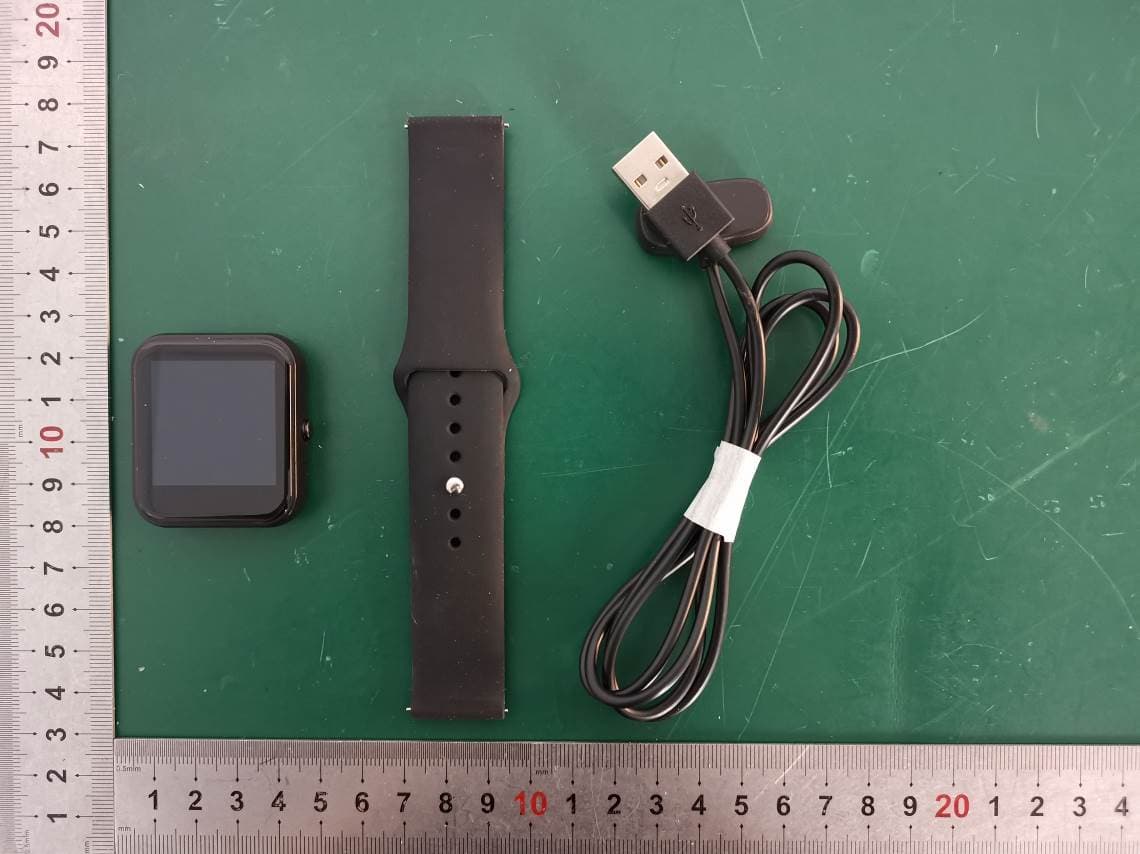
Click to zoom
Application Details
- Equipment Class
- UWB - Ultra Wideband Transmitter
- Date of Grant
- Jul 04, 2023
- Application Purpose
- Original Equipment
- Date of Application
- Jun 04, 2023
- Equipment Note
- UWB Tag
- Frequency Range
- 6489.60000000 - 7987.20000000
- Company
- Woxu Wireless Co.,Ltd.
- Country
- China
Documents & Files
Document Text
Text extracted from the exhibit documents filed with the FCC. Open a document above to read the original.
Users Manual
Version:V01 UT-224 Use and Configuration Manual www.woxuwireless.com 1 / 15 UT-224 use and configuration manual Woxu Wireless Co., Ltd Copyright Version:V01 UT-224 Use and Configuration Manual www.woxuwireless.com 4 / 20 Content 1 Basic introduction of UT-224 ...................................................................................................................... 5 1.1 Main interface ............................................................................................................................. 5 1.2 Heart rate interface ................................................................................................................. 5 1.3 Blood oxygen interface ............................................................................................................. 6 1.4 Step counting interface ........................................................................................................... 7 1.5 Message interface ....................................................................................................................... 8 1.6 Set interface ............................................................................................................................... 8 1.7 Situation bar ............................................................................................................................... 9 1.8 Button ........................................................................................................................................... 10 1.9 UWB ................................................................................................................................................. 10 2 UT-224 Firmware Upgrade Process ........................................................................................................... 10 2.1 Preparation ...................................................................................................................................... 11 2.2 Use nRF Connect software to upgrade the firmware of UT-224 ..................................................... 11 9. Other description ....................................................................................................................................... 16 Version:V01 UT-224 Use and Configuration Manual www.woxuwireless.com 5 / 20 1 Basic introduction of UT-224 UT-224 have six interface and one situation bar,Six interfaces are main interface, heart rate interface, blood oxygen interface, step counting interface, message interface, setting interface. The interface can be switched by swiping left or right, ach interface is responsible for one function, each interface is described in a section below. 1.1 Main interface The main interface is mainly responsible for the display of time and date. Slide to the right and there is no response. Slide to the left and switch to the heart rate interface, the real interface is shown below. 1.2 Heart rate interface Heart rate interface is mainly responsible for heart rate measurement and heart rate display function, Swipe right to switch to the main interface, swipe left to switch to the blood oxygen screen. 1. Start heart rate detection When switching from the main interface or blood oxygen interface to the heart rate interface, And stay in the heart rate interface for 6 seconds when the heart rate detection started(You can see the green light flashing on the back of UT-224), Heart rate results will be detected in about 20 seconds, And updates the heart rate results to the screen in real time. Heart rate interface reminder function:When the heart rate is activated, The heart rate picture flashes at a frequency of 1HZ, When the detection is not started or the result is detected, the icon light is on. 2. Turn off heart rate monitoring Version:V01 UT-224 Use and Configuration Manual www.woxuwireless.com 6 / 16 When switching from the heart rate screen to another screen or turning off the screen, Heart rate monitoring will stop. Heart rate periodic detection function, In the resting situation, the test is performed every five minutes for 40 seconds each time. 1.3 Blood oxygen interface Blood oxygen interface is mainly responsible for blood oxygen measurement and blood oxygen display function, Swipe right to switch to the pedometer screen, swipe left to switch to the heart rate screen. 1. Start the blood oxygen test When you switch from another interface to the blood oxygen interface, And the blood oxygen detection started when the blood oxygen interface stayed for 6 seconds(You can see that the red light on the back of UT-224 is steady on), After about 30 seconds, blood oxygen results will be measured and blood oxygen results will be updated to the screen in real time. Blood oxygen interface reminder function:When the blood oxygen was activated,Blood oxygen images were flickered at a frequency of 1HZ,When the detection is not started or the result is detected, the icon light is on, Meanwhile, a warm reminder phrase "Warm reminder: Please keep your arm still" will be displayed during the detection process. 2. Shut down the blood oxygen test When switching from blood oxygen screen to another screen or turning off the screen, Blood oxygen monitoring will be stop. Version:V01 UT-224 Use and Configuration Manual www.woxuwireless.com 7 / 16 1.4 Step counting interface Step counting interface includes step count and progress, Mainly responsible for step number display function, Swipe right to switch to the message screen, swipe left to switch to the blood oxygen screen. The default target number of steps is 10000, The progress follows the new progress based on the current number of steps,For example, the current walk 2500 steps, the progress into the degree of 25%. As shown in the figure below, 0 represents the number of steps taken, and the small yellow circle represents the progress circle. One round of the progress circle means that 10,000 steps have been taken, and the progress i…
Text truncated - open the document above for the full version.
Attestation Statements
Woxu Wireless Co.,Ltd. Address: No.9 Building Xuzhuang Software Industry Base No 699 8 XuanWu Avenue, Nanjing, China Tel.: 025-83280879 Fax: 025-83280879 E-mail: [email protected] Date: 2022-05-22 F EDERAL COMMUNICATIONS COMMISSIONS Authorization and Evaluation Division 7435 Oakland Mills Road Columbia, MD 21046 Subject: Compliant to FCC § 15.521 technical requirements for FCC ID: 2AKVA-UT224 (a) UWB devices may not be employed for the operation of toys. Operation onboard an aircraft, a ship or a satellite is prohibited. Reply: Compliant. The product is used as a watch and worn on a person's arm. UWB watch shoul d be used with our base station, UWB system will automatically sleep if it is separated fr om us for a long time, and UWB will not work if it is separated from the system.The ships, aircraft and satellites can't get signals from base stations because of distance. (b) Manufacturers and users are reminded of the provisions of § 15.203 and 15.204. Reply: Compliant. There is no any external radio frequency power amplifier or amplifier kit used for this product. And the product is sold together with the antenna, and A permanently attached antenna will be arranged in product. (c) Emissions from digital circuitry used to enable the operation of the UWB transmitter shall comply with the limits in § 15.209, rather than the limits specified in this subpart, provided it can be clearly demonstrated that those emissions from the UWB device are due solely to emissions from digital circuitry contained within the transmitter and that the emissions are not intended to be radiated from the transmitter's antenna. Emissions from associated digital devices, as defined in § 15.3(k), e.g., emissions from digital circuitry used to control additional functions or capabilities other than the UWB transmission, are subject to the limits contained in Subpart B of this part. Reply: All radiation spurious emissions are compliant to FCC § 15.51 9 & 15.209. (d) Within the tables in §§ 15.509, 15.511, 15.513, 15.515, 15.517, and 15.519, the tighter emission limit applies at the band edges. Radiated emission levels at and below 960 MHz are based on measurements employing a CISPR quasi-peak detector. Radiated emission levels above 960 MHz are based on RMS average measurements over a 1 MHz resolution bandwidth. The RMS average measurement is based on the use of a spectrum analyzer with a resolution bandwidth of 1 MHz, an RMS detector, and a 1 millisecond or less averaging time. Unless other wise stated, if pulse gating is employed where the transmitter is quiescent for intervals that are long compared to the nominal pulse repetition interval, measurements shall be made with the pulse train gated on. Alternative measurement procedures may be considered by the Commission. Reply: According to testing requirements, all radiation spurious emissions are compliant to UWB limits for FCC 15.51 9, including for the tighter emission limit applies at the band edges. (e) The frequency at which the highest radiated emission occurs, f M , must be contained within the UWB bandwidth. Reply: Compliant. The f M is contained within the UWB bandwidth, such as 10dB bandwidth. (f) Imaging systems may be employed only for the type of information exchange described in their specific definitions contained in § 15.503. The detection of tags or the transfer or data or voice information is not permitted under the standards for imaging systems. Reply: The product is not used for imaging system. (g) When a peak measurement is required, it is acceptable to use a resolution bandwidth other than the 50 MHz specified in this subpart. This resolution bandwidth shall not be lower than 1 MHz or greater than 50 MHz, and the measurement shall be centered on the frequency at which the highest radiated emission occurs, fM. If a resolution bandwidth other than 50 MHz is employed, the peak EIRP limit shall be 20 log (RBW/50) dBm where RBW is the resolution bandwidth in megahertz that is employed. This may be converted to a peak field strength level at 3 meters using E(dBuV/m) = P(dBm EIRP) + 95.2. If RBW is greater than 3 MHz, the application for certification filed with the Commission must contain a detailed description of the test procedure, calibration of the test setup, and the instrumentation employed in the testing. Reply: Complaint. Testing Peak as the requirements for the test procedure, calibration of the test setup, and the instrumentation employed. (h) The highest frequency employed in § 15.33 to determine the frequency range over which radiated measurements are made shall be based on the center frequency, fC, unless a higher frequency is generated within the UWB device. For measuring emission levels, the spectrum shall be investigated from the lowest frequency generated in the UWB transmitter, without going below 9 kHz, up to the frequency range shown in § 15.33(a) or up to fC + 3/(pulse width in seconds), whichever is higher. There is no requirement to measure emissions beyond 40 GHz provided fC is less than 10 GHz; beyond 100 GHz if fC is at or above 10 GHz and below 30 GHz; or beyond 200 GHz if fC is at or above 30 GHz. Reply: Compliant. Testing range is 9kHz to 40GHz, which compliant to this requirement for this product. And all radiation spurious emissions are compliant to UWB limits for FCC 15.51 9. (i) The prohibition in § 2.201(f) and 15.5(d) of this chapter against Class B (damped wave) emissions does not apply to UWB devices operating under this subpart. Reply: This product will not produce Class B emissions (damped wave). (j) Responsible parties are reminded of the other standards and requirements cross referenced in § 15.505, such as a limit on emissions conducted onto the AC power lines. R eply: Compliant. This product is tested and met the limit for AC power lines conducted emission about FCC 15.207(a) Sincerely, Signature Name: Wang Xiang Title: Purchase Dep.
Attestation Statements
CFR 47 §2.911(d)(7) U.S Agent U.S. AGENT LETTER OF ATTESTATION Date: 2022-12-12 FEDERAL COMMUNICATIONS COMMISSION Authorization and Evaluation Division 7435 Oakland Mills Road Columbia, MD 21046 Ref: Attestation Statements Part 2.911(d)(7) Filing FCC ID: 2AKVA-UT224 Woxu Wireless Co.,Ltd. (“the Applicant”) certifies that, as of the date of the filing of the application, Everguard Inc. (U.S. agent). is our designated U.S. agent for service of process for the above referenced FCC ID. Woxu Wireless Co.,Ltd. (“the Applicant”)accepts to maintain an agent for no less than one year after the grantee has terminated all marketing and importation or the conclusion of any Commission-related proceeding involving the equipment. Everguard Inc. (U.S. agent) accepts, as of the date of the filing of the application, the obligation of the designated U.S. agent for service of process for the above referenced FCC ID. Designated U.S. Agent Information: Company Name: Everguard Inc. Address: 100 Spectrum Center Drive STE 450 Irvine CA 92618 USA Email: [email protected] Signed by (printed name): Sundeep Ahluwalia Signature: Applicant: Woxu Wireless Co.,Ltd. ADD: No.9 Building Xuzhuang Software Industry Base No 699 8 XuanWu Avenue, Nanjing, China TEL: 025 -83280879 E-mail: [email protected] Signed by (printed name): Wang Xiang Signature:
Cover Letter(s)
QA-FR-171-A Woxu Wireless Co.,Ltd. ADD: No.9 Building Xuzhuang Software Industry Base No 699 8 XuanWu Avenue, Nanjing, China TEL: 025-83280879 FAX: 025-83280879 E-mail: [email protected] FCC Confidential Authorization Date: 2022-12-12 FEDERAL COMMUNICATIONS COMMISSIONS Authorization and Evaluation Division 7435 Oakland Mills Road Columbia, MD 21046 Subject: Confidentiality Request regarding application for certification of FCC ID: 2AKVA-UT224 In accordance with Sections 0.457 and 0.459 of the Commission’s Rules, (Woxu Wireless Co.,Ltd.) hereby requests long-term confidential treatment of information accompanying this application as outlined below: Block Diagram Schematics Operation Description The above materials contain proprietary and confidential information not customarily released to the public. The public disclosure of these materials provides unjustified benefits to its competitors in the market. Sincerely, Signature: Printed Name: Wang Xiang Title: Purchase Dep.
External Photos
EXHIBIT B - EUT EXTERNAL PHOTOGRAPHS
ID Label/Location Info
MODEL:UT-224; UWB ID:123456 Power:DC 5V FCC ID:2AKVA-UT224
Internal Photos
EXHIBIT C - EUT INTERNAL PHOTOGRAPHS NFC Antenna BLE Antenna UWB Antenna
RF Exposure Info
China Certification ICT Co., Ltd (Dongguan) Report No.: CR221260878-00B Page 55 of 55 5. RF EXPOSURE EVALUATION 5.1 Applicable Standard According to §1.1307(b)(3)(ii)(A) the 1-mW exemption intended for single transmitters may be also applied to simultaneous transmission conditions, within the same host device, according one of the following criteria: a) When maximum available power each individual transmitting antenna within the same time averaging period is ≤ 1 mW, and the nearest parts of the antenna structures of the simultaneously operating transmitters are separated by at least 2 cm. b) When the aggregate maximum available power of all transmitting antennas is ≤ 1 mW in the same time averaging period. This exemption may not be combined with any other exemption. 5.2 Measurement Result Radio Frequency (MHz) Conducted output power including Tune- up Tolerance Antenna Gain (dBi) The Greater of Conducted Power or ERP (dBm) dBm mW BLE 2402-2480 -1 -1.0 -1 0.79 UWB 6489.6-7987.2 / / -10.5 0.09 Note: 1. Maximum EIRP of UWB is -8.84 dBm, so EPR is -10.99dBm, the tune –up ERP is -10.5dBm. 2. ERP (dBm) = EIRP (dBm)-2.15dB 4. The Value of Maximum Conducted Power including Tune-up Tolerance was declared by the customer. 5. The UWB and BLE can transmit simultaneously. Total power P total = P BLE + P UWB = 0.79+0.09 = 0.88 < 1 mW. Result: The device compliant the 1-mW Test Exemption. ===== END OF REPORT =====
Test Report
Project: UT-224 Author: Jack Li Fil e Name: F-WX0213-03-R Date: 2023-05-15 Revision: A02 Zhejiang Diverse Communication Technology Co., Ltd Building 4, No.1, Chanzhi Road, Quzhou City, Zhejiang Province, China 1 / 10 DIVERSE APPROVAL SHEET UT-224 UWB Antenna Project Name UT-224 WoXu PN AE20-UWDI00-00 DCT PN F-WX0213-03-R Vendor Name DCT Description (Version) A02 Project: UT-224 Author: Jack Li File Name: F-WX0213-03-R Date: 2023-05-15 Revision: A02 CONFIDENTIAL Zhejiang Diverse Communication Technology Co., Ltd 2 / 10 1 ANTENNA DESCRIPTION ......................................................................... 3 1.1 Part number ................................................................................................................................. 3 1.2 Product pictures ........................................................................................................................... 3 1.3 Antenna pictures .......................................................................................................................... 3 2 ELECTRICAL PERFORMANCE ................................................................ 4 2.1 Proposal specification for mass production ............................................................................... 4 2.1.1 VSWR specification ............................................................................................................... 4 2.2 Measurement Set-up.................................................................................................................... 4 2.2.1 VSWR and return loss ............................................................................................................ 4 2.2.2 Efficiency, Gain ...................................................................................................................... 4 2.3 Reference measurement data...................................................................................................... 5 2.3.1 VSWR .................................................................................................................................... 5 2.3.2 Efficiency and Gain ................................................................................................................ 5 3 PLOTS ........................................................................................................ 6 3.1 VSWR ........................................................................................................................................... 6 3.2 Radiation pattern ......................................................................................................................... 7 4 MECHANICAL DESCRIPTION ................................................................ 10 4.1 Drawings ..................................................................................................................................... 10 Project: UT-224 Author: Jack Li File Name: F-WX0213-03-R Date: 2023-05-15 Revision: A02 CONFIDENTIAL Zhejiang Diverse Communication Technology Co., Ltd 3 / 10 1 Antenna description The antenna is a dipole antenna. The structure of the antenna is FPC type. 1.1 Part number DCT PN: F-WX0213-03-R WoXu PN: AE20-UWDI00-00 Vender Name: DCT 1.2 Product pictures Picture1. Product pictures 1.3 Antenna pictures Picture 2. Antenna pictures X Y Project: UT-224 Author: Jack Li File Name: F-WX0213-03-R Date: 2023-05-15 Revision: A02 CONFIDENTIAL Zhejiang Diverse Communication Technology Co., Ltd 4 / 10 2 Electrical Performance 2.1 Proposal specification for mass production 2.1.1 VSWR specification The performance was tested in UT-224 product. Frequency (GHz) 6.1 6.4896 6.9 7.6 7.9872 8.4 VSWR ≤2 ≤2 ≤2 ≤2 ≤2 ≤2 2.2 Measurement Set-up 2.2.1 VSWR and return loss VSWR measurements (S 11 ) were performed using an Agilent ENA series Network Analyser and the previously described test fixture. Coaxial chokes were used to mitigate surface currents on the outside of the cabling. The testing was performed in free space. 2.2.2 Efficiency, Gain The gain of the antenna was measured in DCT’s 3D anechoic chamber in Zhejiang, China. The chamber is standard Satimo with 32 probes system capable of doing tests from 400MHz to 10GHz. Coaxial chokes on the feed cable were used to mitigate surface currents during passive tests. The measurement results are calibrated using dipole standards. Chamber SATIMO Chamber Network Analyzer KEYSIGHT E5071C Comprehensive Tester R&S CMW 500 Temperature 20±2°C Humidity 50±20%rh Project: UT-224 Author: Jack Li File Name: F-WX0213-03-R Date: 2023-05-15 Revision: A02 CONFIDENTIAL Zhejiang Diverse Communication Technology Co., Ltd 5 / 10 2.3 Reference measurement data 2.3.1 VSWR UWB Antenna: Frequency (GHz) 6.1 6.3 6.4896 6.7 6.9 7.6 7.8 7.9872 8.2 8.4 VSWR 1.7 1.5 1.1 1.3 1.5 1.5 1.5 1.5 1.8 1.9 2.3.2 Efficiency and Gain UWB Antenna Frequency, MHz Efficiency, dB Gain, dBi 6100 -5.4 -1.4 6200 -5.3 -0.8 6300 -4.9 0.2 6400 -4.6 0.7 6489.6 -4.3 1.0 6600 -4.0 1.2 6700 -4.0 1.3 6800 -3.9 1.3 6900 -4.0 1.1 7600 -4.0 1.3 7700 -4.0 1.5 7800 -4.1 2.0 7900 -4.3 2.1 7987.2 -4.5 2.2 8100 -4.7 2.5 8200 -5.0 2.7 8300 -5.1 3.1 8400 -5.2 3.3 Project: UT-224 Author: Jack Li File Name: F-WX0213-03-R Date: 2023-05-15 Revision: A02 CONFIDENTIAL Zhejiang Diverse Communication Technology Co., Ltd 6 / 10 3 Plots 3.1 VSWR Picture 3. Antenna VSWR Results Project: UT-224 Author: Jack Li File Name: F-WX0213-03-R Date: 2023-05-15 Revision: A02 CONFIDENTIAL Zhejiang Diverse Communication Technology Co., Ltd 7 / 10 3.2 Radiation pattern 4-1. antenna radiation pattern (theta=90deg) Project: UT-224 Author: Jack Li File Name: F-WX0213-03-R Date: 2023-05-15 Revision: A02 CONFIDENTIAL Zhejiang Diverse Communication Technology Co., Ltd 8 / 10 4-2. antenna radiation pattern (Phi=0deg) Project: UT-224 Author: Jack Li File Name: F-WX0213-03-R Date: 2023-05-15 Revision: A02 CONFIDENTIAL Zhejiang Diverse Communication Technology Co., Ltd 9 / 10 4-3. antenna radiation p…
Text truncated - open the document above for the full version.
Test Report
TEST REPORT Applicant: Woxu Wireless Co.,Ltd. Address: No.9 Building Xuzhuang Software Industry Base No 699 8 XuanWu Avenue Nanjing China FCC ID: 2AKVA-UT224 Product Name: UWB Tag Standard(s): FCC PART 15, Subpart F ANSI C63.10-2013 The above equipment has been tested and found compliant with the requirement of the relative standards by China Certification ICT Co., Ltd (Dongguan) Report Number: CR221260878-00B Date Of Issue: 2023/5/26 Reviewed By: Sun Zhong Title: Manager Test Laboratory: China Certification ICT Co., Ltd (Dongguan) No. 113, Pingkang Road, Dalang Town, Dongguan, Guangdong, China Tel: +86-769-82016888 China Certification ICT Co., Ltd (Dongguan) Report No.: CR221260878-00B Page 2 of 55 Test Facility The Test site used by China Certification ICT Co., Ltd (Dongguan) to collect test data is located on the No. 113, Pingkang Road, Dalang Town, Dongguan, Guangdong, China. The lab has been recognized as the FCC accredited lab under the KDB 974614 D01 and is listed in the FCC Public Access Link (PAL) database, FCC Registration No. : 442868, the FCC Designation No. : CN1314. The lab has been recognized by Innovation, Science and Economic Development Canada to test to Canadian radio equipment requirements, the CAB identifier: CN0123. Declarations China Certification ICT Co., Ltd (Dongguan) is not responsible for the authenticity of any test data provided by the applicant. Data included from the applicant that may affect test results are marked with a triangle symbol “▲”. Customer model name, addresses, names, trademarks etc. are not considered data. Unless otherwise stated the results shown in this test report refer only to the sample(s) tested. This report cannot be reproduced except in full, without prior written approval of the Company. This report is valid only with a valid digital signature. The digital signature may be available only under the Adobe software above version 7.0. This report may contain data that are not covered by the accreditation scope and shall be marked with an asterisk “★”. China Certification ICT Co., Ltd (Dongguan) Report No.: CR221260878-00B Page 3 of 55 CONTENTS T EST FACILITY .......................................................................................................................................... 2 DECLARATIONS .......................................................................................................................................... 2 DOCUMENT REVISION HISTORY .......................................................................................... 5 1. GENERAL INFORMATION .................................................................................................... 6 1.1 PRODUCT DESCRIPTION FOR EQUIPMENT UNDER TEST (EUT) ....................................................... 6 1.2 DESCRIPTION OF TEST CONFIGURATION ........................................................................................... 7 1.2.1 EUT Operation Condition: ............................................................................................................................. 7 1.2.2 Support Equipment List and Details .............................................................................................................. 7 1.2.3 Support Cable List and Details ...................................................................................................................... 7 1.2.4 Block Diagram of Test Setup ......................................................................................................................... 7 1.3 MEASUREMENT UNCERTAINTY .......................................................................................................... 9 2. SUMMARY OF TEST RESULTS .......................................................................................... 10 3. REQUIREMENTS AND TEST PROCEDURES .................................................................. 11 3.1 AC LINE CONDUCTED EMISSIONS .................................................................................................... 11 3.1.1 Applicable Standard ..................................................................................................................................... 11 3.1.2 EUT Setup.................................................................................................................................................... 12 3.1.3 EMI Test Receiver Setup ............................................................................................................................. 12 3.1.4 Test Procedure ............................................................................................................................................. 13 3.1.5 Corrected Amplitude & Margin Calculation ................................................................................................ 13 3.2 RADIATED EMISSIONS BELOW 960 MHZ ......................................................................................... 14 3.2.1 Applicable Standard ..................................................................................................................................... 14 3.2.2 EUT Setup.................................................................................................................................................... 14 3.2.3 EMI Test Receiver ....................................................................................................................................... 14 3.2.4 Test Procedure ............................................................................................................................................. 15 3.2.5 Corrected Amplitude & Margin Calculation ................................................................................................ 15 3.3 RADIATED EMISSIONS ABOVE 960 MHZ .......................................................................................... 16 3.3.1 Applicable Standard ...........................................…
Text truncated - open the document above for the full version.
Test Setup Photos
EXHIBIT D - TEST SETUP PHOTOGRAPHS Conducted Emissions Front View Conducted Emissions Side View Radiated Emission Below 1GHz View Radiated Emission Below 1GHz View Radiated Emission Above 1GHz View Radiated Emission Above 18-26.5GHz View Radiated Emission Above 26.5-40GHz View
Contact Information
Applicant
Wang Xiang(Purchase Dep.)
Test Firm
CHINA CERTIFICATION ICT CO., LTD (DONGGUAN)Tanie Ou
[email protected]0086 0769 86858888
Technical Specifications
| # | Rule Parts | Frequency Range | Power Output |
|---|---|---|---|
| 1 | 15F | 6.49 GHz - 7.99 GHz | - |
Other Applications from Woxu Wireless Co.,Ltd.
2AKVA-UT206Z
Sep 09, 2020UWB Tag
Equipment Class
UWB - Ultra Wideband Transmitter
2AKVA-UT206
Jul 26, 2020UWB Tag
Equipment Class
UWB - Ultra Wideband Transmitter