2AL95-M6Feature phone
AGM Group Limited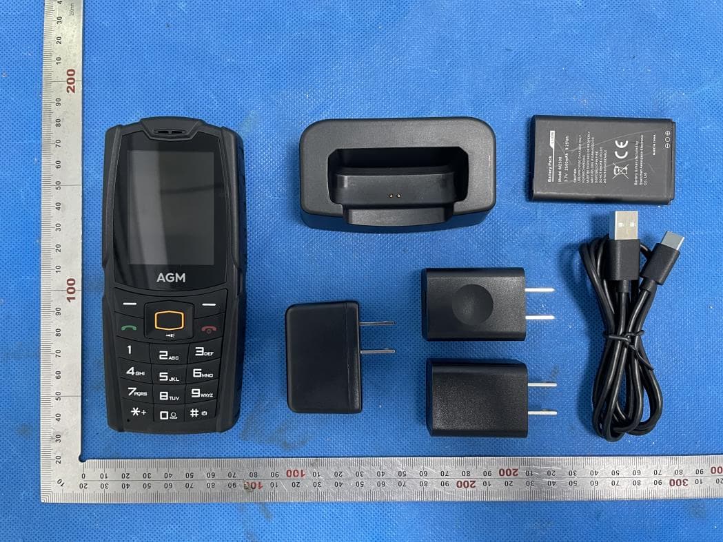
Click to zoom
Application Details
- Equipment Class
- DTS - Digital Transmission System
- Date of Grant
- Jun 27, 2021
- Application Purpose
- Original Equipment
- Date of Application
- Jun 27, 2021
- Equipment Note
- Feature phone
- Frequency Range
- 2402.00000000 - 2480.00000000
- Company
- AGM Group Limited
- Country
- Samoa
Documents & Files
Document Text
Text extracted from the exhibit documents filed with the FCC. Open a document above to read the original.
Users Manual
INSTALLING A MICRO SIM CARD OR MICRO SD CARD FCC RF EXPOSURE INFORMATION: WARNING!! Read this information before using your phone In August 1986 the Federal Communications Commission (FCC) of the United States with its action in Report and Outer FCC 96-326 adopted an updated safety standard for human exposure to radio frequency (RF) electromagnetic energy emitted by FCC regulated transmitters. Those guidelines are consistent with the safety standard previously set by both U.S. and international standards bodies. The design of this phone complies with the FCC guidelines and these international standards. Use only the supplied or an approved antenna. Unauthorized antennas modifications, or attachments could impair call quality, damage the phone, or result in violation of FCC regulations. Do not use the phone with a damaged antenna. If a damaged antenna comes into contact with the skin, a minor burn may result. Please contact your local dealer for replacement antenna. BODY-WORN OPERATION: This device was tested for typical body-worn operations with the back/front of the phone kept 0.5cm from the body. To comply with FCC RF exposure requirements, a minimum separation distance of 0.5cm must be maintained between the user's body and the back/front of the phone, including the antenna. Third-party belt-clips, holsters and similar accessories containing metallic components shall not be used. Body-worn accessories that cannot maintain 0.5cm separation distance between the user’s body and the back/front of the phone, and have not been tested for typical body-worn operations may not comply with FCC RF exposure limits and should be avoided. For more information about RF exposure, please visit the FCC website at www.fcc.gov Your wireless handheld portable telephone is a low power radio transmitter and receiver. When it is ON, it receives and also sends out radio frequency (RF) signals. In August, 1996, the Federal Communications Commissions (FCC) adopted RF exposure guidelines with safety levels for hand- held wireless phones. Those guidelines are consistent with the safety standards previously set by both U.S. and international standards bodies: <ANSIC95.1> (1992) / <NCRP Report 86> (1986) / <ICNIRP> (1999) Those standards were based on comprehensive and periodic evaluations of the relevant scientific literature. For example, over 120 scientists, engineers, and physicians from universities, government health agencies, and industry reviewed the available body of research to develop the ANSI Standard (C95.1). Nevertheless, we recommend that you use a hands-free kit with your phone (such as an earpiece or headset) to avoid potential exposure to RF energy. The design of your phone complies with the FCC guidelines (and those standards). Use only the supplied or an approved replacement antenna. Unauthorized antennas, modifications, or attachments could damage the phone and may violate FCC regulations. NORMAL POSITION: Hold the phone as you would any other telephone with the antenna pointed up and over your shoulder. RF Exposure Information: This product is compliance to FCC RF Exposure requirements and refers to FCC website https://apps.fcc.gov/oetcf/eas/reports/GenericSearch.cfm search for FCC ID: 2AL95-M6 to gain further information include SAR Values. This device complies with part 15 of the FCC rules. Operation is subject to the following two conditions: (1) this device may not cause harmful interference, and (2) this device must accept any interference received, including interference that may cause undesired operation. NOTE: The manufacturer is not responsible for any radio or TV interference caused by unauthorized modifications to this equipment. Such modifications could void the user’s authority to operate the equipment. NOTE: This equipment has been tested and found to comply with the limits for a Class B digital device, pursuant to part 15 of the FCC Rules. These limits are designed to provide reasonable protection against harmful interference in a residential installation. This equipment generates uses and can radiate radio frequency energy and, if not installed and used in accordance with the instructions, may cause harmful interference to radio communications. However, there is no guarantee that interference will not occur in a particular installation. If this equipment does cause harmful interference to radio or television reception, which can be determined by turning the equipment off and on, the user is encouraged to try to correct the interference by one or more of the following measures: - Reorient or relocate the receiving antenna. - Increase the separation between the equipment and receiver. -Connect the equipment into an outlet on a circuit different from that to which the receiver is connected. -Consult the dealer or an experienced radio/TV technician for help Changes or modifications to this unit not expressly approved by the party responsible for compliance could void the user’s authority to operate the equipment.
Cover Letter(s)
AGM Group Limited Jun.24, 2021 Office of Engineering Technology Federal Communications Commission 7435 Oakland Mills Road Columbia, MD 21046 USA Subject: Explanation of differences between product types FCC ID : 2AL95-M6 Model Number: M6, M6 SE, M6 PRO To Whom It May Concern: We, The AGM Group Limited hereby declare that the model : M6 SE, M6 PRO is identical with the model : M6, except the model name. Except for the different above, no other modification is performed. Sincerely, Signature: AGM Group Limited Contact person: Song Pan
Cover Letter(s)
AGM Group Limited Agent Authorization Company: AGM Group Limited Address: Level 5, Development Bank of Samoa Building. Beach Road, Apia, Samoa Product Name: Feature phone Model Number(s): M6, M6 SE, M6 PRO Product Description: Feature phone We authorize MiCOM Labs Inc., 575 Boulder Court, Pleasanton, California 94566, USA, to act on our behalf on all matters concerning the certification of above named equipment. We declare that MiCOM Labs Inc. is allowed to forward all information related to the approval and certification of equipment to the regulatory agencies as required and to discuss any issues concerning the approval application. Any and all acts carried out by MiCOM Labs on our behalf shall have the same effect as acts of our own. Signature: Date: 2021-06-24 Name: Song Pan Company: AGM Group Limited
Cover Letter(s)
AGM Group Limited Office of Engineering Technology Federal Communications Commission 7435 Oakland Mills Road Columbia, MD 21046 USA Date: 2021-06-24 Subject; Request for Confidentiality FCC ID: 2AL95-M6 To Whom It May Concern, Pursuant to the provisions of the Commission’s rules Title 47 Sections §0.457 and §0.459, we are requesting the Commission to withhold the following attachment(s) as confidential documents from public disclosure indefinitely. These documents contain detailed system and equipment descriptions and are considered as proprietary information in operation of the equipment. The public disclosure of these documents might be harmful to our company and would give competitors an unfair advantage in the market. Schematic Diagram Block Diagram Parts List Operational Description Tune-up Procedure In additional to above mentioned documents, in order to comply with the marketing regulations in Title 47 CFR §2.803 and the importation rules in Title 47 CFR §2.1204, while ensuring that business sensitive information remains confidential until the actual marketing of newly authorized devices, we request Short Term Confidentiality of the following attachment(s); External Photos Test Setup Photos Internal Photos User Manual For 45 days, pursuant to Public Notice DA 04-1705. OR For 180 days pursuant to KDB 726920 D01. It is our understanding that all measurement test reports, FCC ID label format and correspondence during the certification review process cannot be granted as confidential documents and this information will be available for public review once the grant of equipment authorization is issued. Sincerely AGM Group Limited Contact person: Song Pan
External Photos
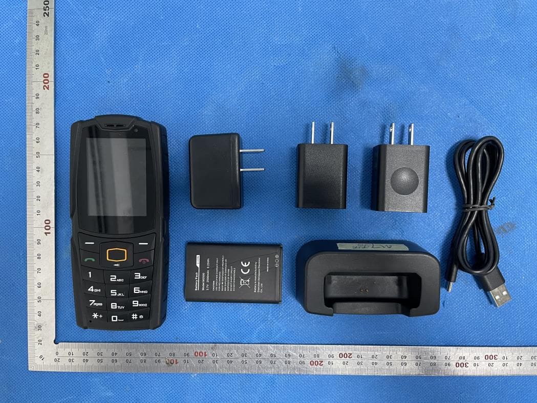
External Photos All VIEW OF EUT TOP VIEW OF EUT BOTTOM VIEW OF EUT FRONT VIEW OF EUT BACK VIEW OF EUT LEFT VIEW OF EUT RIGHT VIEW OF EUT ADAPTER 1: TPA-97H050100UW01 ADAPTER 2: DCS10-0501000F ADAPTER 3: TPA-46B050100UU
Internal Photos
Internal Photos OPEN VIEW OF EUT(FIGURE 1) OPEN VIEW OF EUT(FIGURE 2) OPEN VIEW OF EUT(FIGURE 3) OPEN VIEW OF EUT(FIGURE 3) GSM& WCDMA& LTE ANTENNA GSM/WCDMA/LTE Antenna BT Antenna Diversity Antenna DIVERSITY ANTENNA BT ANTENNA INTERNAL VIEW OF EUT(FIGURE 1) INTERNAL VIEW OF EUT(FIGURE 2) INTERNAL VIEW OF EUT(FIGURE 3) INTERNAL VIEW OF EUT(FIGURE 4) INTERNAL VIEW OF EUT(FIGURE 5) INTERNAL VIEW OF EUT(FIGURE 6) INTERNAL VIEW OF EUT(FIGURE 7)
Test Report
Page 1 of 50 FCC Test Report Report No.: AGC00408210105FE02 FCC ID : 2AL95-M6 APPLICATION PURPOSE : Original Equipment PRODUCT DESIGNATION : Feature phone BRAND NAME : AGM MODEL NAME : M6, M6 SE, M6 PRO APPLICANT : AGM Group Limited DATE OF ISSUE : Jun. 22, 2021 STANDARD(S) : FCC Part 15.247 REPORT VERSION : V1.0 Attestation of Global Compliance (Shenzhen) Co., Ltd Report No.: AGC00408210105FE02 Page 2 of 50 REPORT REVISE RECORD Report Version Revise Time Issued Date Valid Version Notes V1.0 / Jun. 22, 2021 Valid Initial Release Report No.: AGC00408210105FE02 Page 3 of 50 TABLE OF CONTENTS 1. VERIFICATION OF COMPLIANCE .................................................................................................................. 5 2. GENERAL INFORMATION .............................................................................................................................. 6 2.1. PRODUCT DESCRIPTION ........................................................................................................................ 6 2.2. TABLE OF CARRIER FREQUENCYS ....................................................................................................... 6 2.3. RELATED SUBMITTAL(S)/GRANT(S) ....................................................................................................... 7 2.4. TEST METHODOLOGY ............................................................................................................................. 7 2.5. SPECIAL ACCESSORIES .......................................................................................................................... 7 2.6. EQUIPMENT MODIFICATIONS ................................................................................................................. 7 2.7. ANTENNA REQUIREMENT ....................................................................................................................... 7 3. MEASUREMENT UNCERTAINTY ................................................................................................................... 8 4. DESCRIPTION OF TEST MODES ................................................................................................................... 9 5. SYSTEM TEST CONFIGURATION ................................................................................................................ 10 5.1. CONFIGURATION OF TESTED SYSTEM ............................................................................................... 10 5.2. EQUIPMENT USED IN TESTED SYSTEM .............................................................................................. 10 5.3. SUMMARY OF TEST RESULTS .............................................................................................................. 10 6. TEST FACILITY .............................................................................................................................................. 11 7. PEAK OUTPUT POWER ................................................................................................................................ 12 7.1. MEASUREMENT PROCEDURE .............................................................................................................. 12 7.2. TEST SET-UP (BLOCK DIAGRAM OF CONFIGURATION) .................................................................... 12 7.3. LIMITS AND MEASUREMENT RESULT .................................................................................................. 13 8. 6 DB BANDWIDTH ......................................................................................................................................... 15 8.1. MEASUREMENT PROCEDURE .............................................................................................................. 15 8.2. TEST SET-UP (BLOCK DIAGRAM OF CONFIGURATION) .................................................................... 15 8.3. LIMITS AND MEASUREMENT RESULTS ............................................................................................... 15 9. CONDUCTED SPURIOUS EMISSION........................................................................................................... 17 9.1. MEASUREMENT PROCEDURE .............................................................................................................. 17 9.2. TEST SET-UP (BLOCK DIAGRAM OF CONFIGURATION) .................................................................... 17 9.3. MEASUREMENT EQUIPMENT USED .................................................................................................... 17 9.4. LIMITS AND MEASUREMENT RESULT .................................................................................................. 17 10. MAXIMUM CONDUCTED OUTPUT POWER SPECTRAL DENSITY ........................................................ 25 Report No.: AGC00408210105FE02 Page 4 of 50 10.1. MEASUREMENT PROCEDURE ............................................................................................................ 25 10.2. TEST SET-UP (BLOCK DIAGRAM OF CONFIGURATION) .................................................................. 25 10.3. MEASUREMENT EQUIPMENT USED .................................................................................................. 25 10.4. LIMITS AND MEASUREMENT RESULT................................................................................................ 25 11. RADIATED EMISSION ................................................................................................................................. 27 11.1. MEASUREMENT PROCEDURE ............................................................................................................ 27 11.2. TEST SETUP .......................................................................................................................................... 28 11.3. LIMITS AND MEASUREMENT RESULT................................................................................................ 29 11.4. TE…
Text truncated - open the document above for the full version.
Test Setup Photos
Test Setup Photos RADIATED EMISSION TEST SETUP BELOW 1GHZ RADIATED EMISSION TEST SETUP ABOVE 1GHZ Mode No.: DCS10-0501000F CONDUCTED EMISSION TEST SETUP Mode No.: TPA-46B050100UU CONDUCTED EMISSION TEST SETUP Mode No.: TPA-97H050100UW01 CONDUCTED EMISSION TEST SETUP
Contact Information
Applicant
Song Pan
Technical Contact
Test Firm
Attestation of Global Compliance (Shenzhen) Co., LDoris Li
[email protected]+86-755-25234088
Technical Specifications
| # | Rule Parts | Frequency Range | Power Output |
|---|---|---|---|
| 1 | 15C | 2.40 GHz - 2.48 GHz | 3.20 mW |
Other Applications from AGM Group Limited
2AL95-M7
May 10, 2021Smart phone
Equipment Class
DTS - Digital Transmission System