2ALAI23MT105IND246
Mettler Toledo (Changzhou) Measurement Technology Ltd.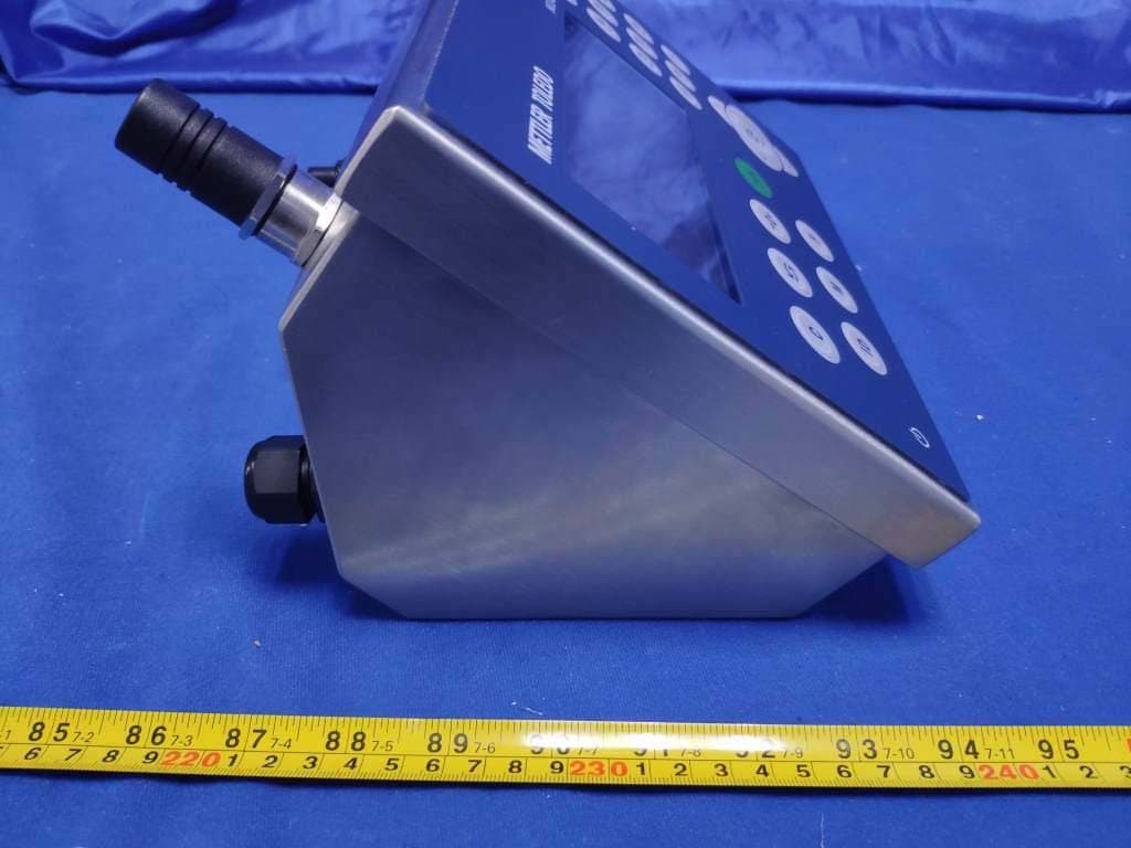
Click to zoom
Application Details
- Equipment Class
- DTS - Digital Transmission System
- Date of Grant
- Feb 13, 2024
- Application Purpose
- Original Equipment
- Date of Application
- Feb 13, 2024
- Equipment Note
- IND246
- Frequency Range
- 2412.00000000 - 2462.00000000
- Country
- China
Documents & Files
Document Text
Text extracted from the exhibit documents filed with the FCC. Open a document above to read the original.
Users Manual
User Manual IND246 for PJA5 Weighing Terminal Congratulations on choosing the quality and precision of METTLER TOLEDO. Proper use of your new equipment according to this Manual and regular calibration and maintenance by our factory-trained service team ensures dependable and accurate operation, protecting your investment. Contact us about a service agreement tailored to your needs and budget. Further information is available at www.mt.com/service. There are several important ways to ensure you maximize the performance of your investment: 1Register your product: We invite you to register your product at www.mt.com/productregistration so we can contact you about enhancements, updates and important notifications concerning your product. 2Contact METTLER TOLEDO for service: The value of a measurement is proportional to its accuracy – an out of specification scale can diminish quality, reduce profits and increase liability. Timely service from METTLER TOLEDO will ensure accuracy and optimize uptime and equipment life. Installation, Configuration, Integration and Training: Our service representatives are factory-trained weighing equipment experts. We make certain that your weighing equipment is ready for production in a cost effective and timely fashion and that personnel are trained for success. Initial Calibration Documentation: The installation environment and application requirements are unique for every industrial scale so performance must be tested and certified. Our calibration services and certificates document accuracy to ensure production quality and provide a quality system record of performance. Periodic Calibration Maintenance: A Calibration Service Agreement provides on-going confidence in your weighing process and documentation of compliance with requirements. We offer a variety of service plans that are scheduled to meet your needs and designed to fit your budget. © METTLER TOLEDO 2023 No part of this manual may be reproduced or transmitted in any form or by any means, electronic or mechanical, including photocopying and recording, for any purpose without the express written permission of METTLER TOLEDO. U.S. Government Restricted Rights: This documentation is furnished with Restricted Rights. Copyright 2023 METTLER TOLEDO. This documentation contains proprietary information of METTLER TOLEDO. It may not be copied in whole or in part without the express written consent of METTLER TOLEDO. METTLER TOLEDO reserves the right to make refinements or changes to the product or manual without notice. COPYRIGHT METTLER TOLEDO ® is a registered trademark of Mettler-Toledo, LLC. All other brand or product names are trademarks or registered trademarks of their respective companies. METTLER TOLEDO RESERVES THE RIGHT TO MAKE REFINEMENTS OR CHANGES WITHOUT NOTICE. FCC Notice Product name: Weighing Terminal Model: IND246 FCC ID: 2ALAI23MT105 This device complies with part 15 of the FCC Rules. Operation is subject to the following two conditions: (1) This device may not cause harmful interference, and (2) this device must accept any interference received, including interference that may cause undesired operation. This equipment has been tested and found to comply with the limits for a Class B digital device, pursuant to part 15 of the FCC Rules. These limits are designed to provide reasonable protection against harmful interference in a residential installation. This equipment generates, uses and can radiate radio frequency energy and, if not installed and used in accordance with the instructions, may cause harmful interference to radio communications. However, there is no guarantee that interference will not occur in a particular installation. If this equipment does cause harmful interference to radio or television reception, which can be determined by turning the equipment off and on, the user is encouraged to try to correct the interference by one or more of the following measures: —Reorient or relocate the receiving antenna. —Increase the separation between the equipment and receiver. —Connect the equipment into an outlet on a circuit different from that to which the receiver is connected. —Consult the dealer or an experienced radio/TV technician for help. This equipment complies with FCC radiation exposure limits set forth for uncontrolled equipment and meets FCC radio frequency (RF) Exposure Guidelines. This equipment should be installed and operated with at least 2cm and more between the radiator and person’s hands. Changes or modifications not expressly approved by the party responsible for compliance could void the user's authority to operate the equipment. Declaration of Conformity is available at http://glo.mt.com/global/en/home/search/compliance.html/compliance/. Statement regarding harmful substances We do not make direct use of harmful materials such as asbestos, radioactive substances or arsenic compounds. However, we purchase components from third party suppliers, which may contain some of these substances in very small quantities. Document 64084448 / Rev. 05 / 12/2023 3 Disposal of Electrical and Electronic Equipment In conformance with the European Directive 2012/19/EC on Waste Electrical and Electronic Equipment (WEEE) this device may not be disposed of in domestic waste. This also applies to countries outside the EU, per their specific requirements. Please dispose of this product in accordance with local regulations at the collecting point specified for electrical and electronic equipment. If you have any questions, please contact the responsible authority or the distributor from which you purchased this device. Should this device be passed on to other parties (for private or professional use), the content of this regulation must also be related. Thank you for your contribution to environmental protection. Warnings and Cautions • READ this manual BEFORE operating or servicing this equipment and FOLLOW these instructions carefully. • SAVE this manual for future reference. WARN…
Text truncated - open the document above for the full version.
Users Manual
5-26 Applications 5.4.4.3. Count Out Sequence The IND246 Counting application can be used to count out pieces from a container placed on the scale. This function varies depending on the mode in use. 5.4.4.3.1. Tare-Sample 1. At the Tare? prompt, place the entire container on the scale and press ENTER . 2. At the Sample? prompt, remove the sample quantity from the container and press ENTER . 3. The terminal will display a negative count equal to the sample quantity. As additional pieces are removed the count will update in a negative direction. 5.4.4.3.2. APW If in the Tare-Sample sequence and the display is prompting APW?: 1. Enter the APW of the part and press ENTER . 2. The terminal will display a count of zero pieces. 3. As pieces are removed the count will update in a negative direction. 5.4.4.3.3. Sample-Tare 1. Place the sample pieces on the empty scale and press ENTER . 2. At the Tare? prompt, place the full container on the scale and press ENTER . 3. The terminal will display a count of zero pieces. 4. As pieces are removed from the container, the count will update in a negative direction. 5.4.4.4. Counting a Full Container Parts in a full container can be counted when the terminal is in Sample-Tare mode. 1. Take the sample as normal. 2. At the Tare? prompt, use the numeric keypad to enter the preset tare value of the container and press ENTER . 3. Place the full container on the scale. The count will update to show the total number of pieces. 5.4.4.5. Switching from Sample to APW Entry Mode The normal sampling sequence requires taking a sample to determine the APW value for the part. If the APW is already known, it can be entered directly by changing the entry mode from sampling to APW entry. The mode switching icon ( or ) must be enabled in setup (at Application > Counting > Menu Keys) in order to appear on the Operator Menu. When the terminal’s display language is set to English, the icon will appear. If any other language is set, will appear. 5-27 To change the mode from Sampling to APW entry: 1. When the display is prompting Sample?, press the MENU key to access the Operator Menu. 2. Select Sample/APW key or and press ENTER . 3. The prompt will now show APW? and support direct entry of an APW. To change the mode from APW entry to Sampling: 1. When the display is prompting APW?, press the MENU key to access the Operator Menu. 2. Select the Sample/APW key or and press ENTER . 3. The prompt will now show SAMPLE? and support part sampling to determine an APW. 5.4.4.6. Clearing the Counting Cycle When the display is showing the number of pieces in a piece count, the display can be cleared back to the prompting sequence by pressing the CLEAR key twice. The first press of the CLEAR key will clear the tare value and the second press will clear the APW value and return the display to either the Tare? Or Sample? prompt, depending on the operating sequence selected. 5.4.4.7. Recall of Stored IDs An ID Table can be enabled in setup to store up to 99 IDs. This is useful if the APW of the part being counted and the tare weight are consistent. Use of the stored values eliminates the taring and sampling process and shows the piece count immediately. Each part ID is identified by a one- or two-digit ID number, and includes a description, tare weight, APW and (if so configured in setup) an accumulator and counter. An ID Table record can be recalled by one of two methods: • If the ID is not known, the record can be found by viewing the ID Table. • If the ID is known, it can be entered in a Quick Recall sequence. 5.4.4.7.1. Recall from ID Table To recall a record from the ID Table: 1. Press the MENU key to access the Operator Menu. 2. Select ID Table and press ENTER . 3. The first ID record will be displayed, with a scroll bar to the right. 4. Use the UP and DOWN navigation keys to move the view until the desired record is displayed: a. Press ENTER to select the record and return to the counting application b. Press the LEFT arrow to return to the counting application without selecting a record. 5-28 Applications 5.4.4.7.2. Quick ID Recall When the display is in piece-counting mode, a known ID can be recalled directly: 1. Use the numeric keypad to enter the ID. A Data: label will display on line 1 of the display, and the entered number on line 2. 2. Once the ID has been entered, press ID to perform the recall. 3. If the ID is not found in the ID Table, an error message will appear. Clear the message by pressing ENTER . The display will return to the counting mode, using the previous APW value. 5.4.5. Print Formats When a demand print is triggered in the Counting application, the terminal will look for a demand connection to one of the ports using template 9. If such a connection exists, then template 9 will be sent out via the selected port. If there is no demand connection using template 9, a “ No demand connection” error will be displayed. 5.4.5.1. New Print Fields Template 9 contains four new data fields related to the Counting application that are not available in the other templates. These new print fields are: • APW • Piece Count • Record ID (from ID Table) • Record Description (from ID Table) 5.4.5.2. Default Template The default structure for template 9 is shown in Figure 5- 14. Elements in braces {...} are fields of data supplied by the terminal. Figure 5- 15 shows a printed sample of the default template. {String 1} {New line} {String 2} {New line} {Time} {3 spaces} {3 spaces} {Date} {New line} {Displayed Weight} {New line} {Piece Count} {New line} {Record Description} {New line} {End of template} Figure 5- 14: Default Structure of Template 9 Meyer’s Hardware Zurich, Switzerland 16:12:45 Feb 17 2012 12.20 lb N 450 PCS 4M x 12 Screw Figure 5- 15: Print Sample, Default Template 9 5-29 This template can be edited, as described in the Communication section of Chapter 3 of this manual, Configuration > Communication > Templates. 5.4.5.3. Report Format The ID Table Report can be configured a…
Text truncated - open the document above for the full version.
Attestation Statements
* the applicant must designate a contact located in the United States for purposes of acting as the applicant’s agent for service of process, regardless of whether the applicant is a domestic or foreign entity. An applicant located in the United States may designate itself as the agent for service of process. Address Phone Fax 1900 Polaris Parkway, Columbus, OH 43240-4035 (800) METTLER (800) 638-8537 (614) 438-4900 Mettler-Toledo, LLC www.mt.com U.S. Agent Designation for Service of Process - Certification Attestation Letter January 26, 2024 Nemko North America, Inc. 303 River Road Ottawa K1V 1H2 Canada ATTN.: Reviewing Engineer RE: IND246 FCC ID: 2ALAI23MT105 Per section 2.911(d)(7) of the FCC rules, Mettler Toledo (Changzhou) Measurement Technology Co., Ltd. (“the applicant”) certifies that the equipment for which authorization is sought is designated to the following U.S. agent* for service of process: Company Name: Mettler-Toledo, LLC Physical U.S. Company Address: 1900 Polaris Parkway, Columbus, OH 43240 Agent Name: Ray Khouw Agent e-mail address: [email protected] FRN: 0013261102 The above contact person accepts the obligation for service of process. The applicant accepts to maintain an agent for no less than one year after the grantee has terminated all marketing and importation or the conclusion of any Commission-related proceeding involving the equipment. Applicant Signed: Designated Agent Signed: (Required, if different to Applicant): Signed: Signed: Printed name: Michael Xu Printed name: Ray Khouw Title: Senior Product Compliance Engineer Title: Product Safety Compliance Leader Company Name: Mettler Toledo (Changzhou) Measurement Technology Co., Ltd. Company Name: Mettler-Toledo, LLC Date: FRN: January 26, 2024 0026298612 Date: FRN: January 26, 2024 0013261102
Attestation Statements
Covered Equipment Certification Attestation Letter 1/18/2024 Nemko North America, Inc. 303 River Road Ottawa K1V 1H2 Canada ATTN.: Reviewing Engineer FCC ID: 2ALAI23MT105 Signed: Printed name: Michael Xu Title: Senior Product Compliance Engineer Company Name: Mettler Toledo (Changzhou) Measurement Technology Ltd. Date: 1/18/2024 Mettler Toledo (Changzhou) Measurement Technology Co., Ltd. (“the applicant”) certifies that the equipment for which authorization is sought is not “covered” equipment prohibited from receiving an equipment authorization pursuant to section 2.903 of the FCC rules. Note: If the equipment for which the applicant seeks authorization is produced by any of the entities identified on the current Covered List , the applicant should include an explanation on why the equipment is not “covered” equipment. Mettler Toledo (Changzhou) Measurement Technology Co., Ltd. (“the applicant”) certifies that, as of the date of the filing of the application, the applicant is not identified on the Covered List as an entity producing “covered” equipment. Mettler Toledo (Changzhou) Measurement Technology Co., Ltd. No. 111 West Taihu Road, Changzhou City, Jiangsu Province, China.
Cover Letter(s)
No. 111 West Taihu Road, Changzhou City, Jiangsu Province, China. 1/18/2024 Nemko North America, Inc. 303 River Road Ottawa, Ontario, Canada K1V 1H2 REQUEST FOR CONFIDENTIALITY - FCC FCC ID: 2ALAI23MT105 Pursuant to Sections 0.457(d)(1)(ii) and 0.459 of the Commission’s Rules and FCC Guidance document 726920, we hereby request confidential treatment of information accompanying this application as outlined below: PERMANENT LONG-TERM CONFIDENTIALITY: Schematics Block Diagrams Theory of Operation The above information contains trade secrets and proprietary information not customarily released to the public. The public disclosure of this information might be harmful to the applicant and provide unjustified benefits to its competitors. The Applicant understands that pursuant to Rule 0.457(d)(1)(ii), disclosure of this Application and all accompanying materials will not be made before the date of the Grant for this Application. Sincerely, Signed: Printed name: Michael Xu Title: Senior Product Compliance Engineer Mettler Toledo (Changzhou) Measurement Technology Co., Ltd.
Cover Letter(s)
No. 111 West Taihu Road, Changzhou City, Jiangsu Province, China. 1/18/2024 Nemko North America, Inc. 303 River Road Ottawa, Ontario, Canada K1V 1H2 AUTHORITY TO ACT AS AGENT - FCC On our behalf, I appoint Audix Technology (Shanghai) Co., Ltd. (3F 34Bldg 680 Guiping Rd, Caohejing Hi-Tech Park, Shanghai 200233, China), to act as our agent in the preparation of this application for equipment certification. I certify that submitted documents properly describe the device or system for which equipment certification is sought. I also certify that each unit manufactured, imported or marketed, as defined in FCC regulations will have affixed to it a label identical to that submitted for approval with this application. In signing this letter, Applicant certifies that neither the applicant nor any party to the application is not subject to a denial of Federal benefits, that include FCC benefits, pursuant to Section 5301 of the Anti-Drug Abuse Act of 1988, 21 U.S.C. § 862 because of a conviction for possession or distribution of a controlled substance. See 47 CFR 1.2002(b) for the definition of a "party" for these purposes. For instances where our authorized agent signs the application for certification on our behalf, I acknowledge that all responsibility for complying with the terms and conditions for certification, as specified by Nemko North America Inc., still resides still resides with us. Sincerely, Printed name: Michael Xu Mettler Toledo (Changzhou) Measurement Technology Co., Ltd.
External Photos
Appendix II Page 1 of 12 Audix Technology (Shanghai) Co., Ltd. Report No.: ACI-F23224 APPENDIX II P HOTOGRAPHS OF EUT Appendix II Page 2 of 12 Audix Technology (Shanghai) Co., Ltd. Report No.: ACI-F23224 FIGURE 1 IND246 (IND246) G ENERAL APPEARANCE F IGURE 2 IND246 (IND246) FRONT APPEARANCE Appendix II Page 3 of 12 Audix Technology (Shanghai) Co., Ltd. Report No.: ACI-F23224 FIGURE 3 IND246 (IND246) B ACK APPEARANCE F IGURE 4 IND246 (IND246) BOTTOM APPEARANCE Appendix II Page 4 of 12 Audix Technology (Shanghai) Co., Ltd. Report No.: ACI-F23224 FIGURE 5 IND246 (IND246) L EFT APPEARANCE F IGURE 6 IND246 (IND246) RIGHT APPEARANCE
ID Label/Location Info
Label location: Label:
Internal Photos
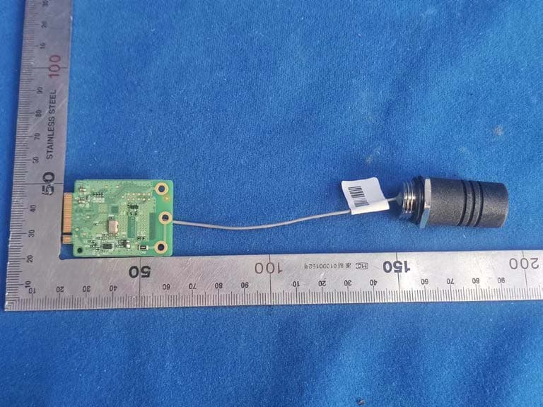
Appendix II Page 5 of 12 Audix Technology (Shanghai) Co., Ltd. Report No.: ACI-F23224 FIGURE 7 IND246 (IND246) C OVER REMOVE F IGURE 8 IND246 (IND246) RF BOARD FRONT Appendix II Page 6 of 12 Audix Technology (Shanghai) Co., Ltd. Report No.: ACI-F23224 FIGURE 9 IND246 (IND246) RF BOARD BACK F IGURE 10 IND246 (IND246) CHIP & CRYSTAL ON RF BOARD Appendix II Page 7 of 12 Audix Technology (Shanghai) Co., Ltd. Report No.: ACI-F23224 FIGURE 11 IND246 (IND246) RF MODULE F IGURE 12 IND246 (IND246) SWITCH BOARD FRONT ANT1 (in use) ANT2 (no use) Appendix II Page 8 of 12 Audix Technology (Shanghai) Co., Ltd. Report No.: ACI-F23224 FIGURE 13 IND246 (IND246) S WITCH BOARD BACK F IGURE 14 IND246 (IND246) CONTROL BOARD FRONT Appendix II Page 9 of 12 Audix Technology (Shanghai) Co., Ltd. Report No.: ACI-F23224 FIGURE 15 IND246 (IND246) C ONTROL BOARD BACK F IGURE 16 IND246 (IND246) POWER BOARD Appendix II Page 10 of 12 Audix Technology (Shanghai) Co., Ltd. Report No.: ACI-F23224 FIGURE 17 IND246 (IND246) P OWER BOARD FRONT F IGURE 18 IND246 (IND246) POWER BOARD BACK Appendix II Page 11 of 12 Audix Technology (Shanghai) Co., Ltd. Report No.: ACI-F23224 FIGURE 19 IND246 (IND246) CHIP&CRYSTAL1 ON POWER BOARD F IGURE 20 IND246 (IND246) CHIP&CRYSTAL2 ON POWER BOARD Appendix II Page 12 of 12 Audix Technology (Shanghai) Co., Ltd. Report No.: ACI-F23224 FIGURE 21 IND246 (IND246) A NTENNA -END-
RF Exposure Info
Mettler Toledo (Changzhou) Measurement Technology Co., Ltd FCC ID: 2ALAI23MT105 Page 1 of 2 Audix Technology (Shanghai) Co., Ltd. RADIO FREQUENCY EXPOSURE EVALATION Evaluation Method KDB 447498 D04 Interim General RF Exposure Guidance v01 Applicable Standard: FCC CFR 47 §1.1307(b)(3)(i)(B): A single RF source is exempt if the available maximum time-averaged power or effective radiated power (ERP), whichever is greater, is less than or equal to the threshold P th (mW) described in the following formula. This method shall only be used at separation distances (cm) from 0.5 centimeters to 40 centimeters and at frequencies from 0.3 GHz to 6 GHz (inclusive). P th is given by: Mettler Toledo (Changzhou) Measurement Technology Co., Ltd FCC ID: 2ALAI23MT105 Page 2 of 2 Audix Technology (Shanghai) Co., Ltd. SAR evaluation: <Passed> Mode Frequency Max output power Ant. Gain Max E.I.R.P P th MHz dBm mW dBi dBm mW mW 802.11b 2412 12.1 16.22 2.5 14.6 28.84 38.6 802.11g 2412 11.84 15.28 2.5 14.34 27.16 38.6 802.11n20 2412 11.81 15.17 2.5 14.31 26.98 38.6 Note1: For this EUT, that is a fixed devices, and the separation distance is 2 cm that declared by manufacturer. Note2: The Conducted output power and Maximum EIRP both no greater than the threshold P th , that meets the exemption, the RF exposure evaluation is not required. -END-
Test Report
Mettler-Toledo (ChangZhou) Measurement Technology LtdFCC ID: 2ALAI23MT105 Page 1 of 75 Audix Technology (Shanghai) Co., Ltd. Report No.: ACI-F23224 Prepared For: Mettler-Toledo (ChangZhou) Measurement Technology Ltd No.111 Taihu West Road Changzhou City, Jiangsu Province, China. Prepared By: Audix Technology (Shanghai) Co., Ltd. 3F, Building 34, No. 680 Guiping Rd., Caohejing, Hi-Tech Park, Shanghai 200233, China Tel: +86-21-64955500 File No. : C1D2311044 Report No. : ACI-F23224 Date of Test : 2023.11.23-12.12 Date of Report : 2023.12.21 TEST REPORT On behalf of Mettler-Toledo (ChangZhou) Measurement Technology Ltd Product Name: IND246 Model No.: IND246 FCC ID: 2ALAI23MT105 The statement is based on a single evaluation of one sample of the above-mentioned products. It does not imply an assessment of the whole production and does not permit the use of the test lab logo. The report must not be used by the client to claim product certification, approval, or endorsement by NVLAP, NIST, or any agency of the U.S. Government. TESTING NVLAP LAB CODE 200371-0 Mettler-Toledo (ChangZhou) Measurement Technology LtdFCC ID: 2ALAI23MT105 Page 2 of 75 Audix Technology (Shanghai) Co., Ltd. Report No.: ACI-F23224 TABLE OF CONTENTS Page 1 SUMMARY OF STANDARDS AND RESULTS .......................................................................... 5 1.1 Description of Standards and Results ......................................................................................... 5 2 GENERAL INFORMATION .......................................................................................................... 6 2.1 Description of Equipment Under Test ........................................................................................ 6 2.2 EUT Specifications Assessed in Current Report ........................................................................ 8 2.3 Test Information ......................................................................................................................... 8 2.4 Duty Cycle Check ...................................................................................................................... 9 2.5 Sample Description .................................................................................................................. 10 2.6 Supported equipment ................................................................................................................ 10 2.7 Description of Test Facility ...................................................................................................... 10 3 RADIATED EMISSION TEST ..................................................................................................... 11 3.1 Test Equipment ......................................................................................................................... 11 3.2 Block Diagram of Test Setup ................................................................................................... 12 3.3 Radiated Emission Limit (§15.209) ......................................................................................... 13 3.4 Test Configuration .................................................................................................................... 13 3.5 Operating Condition of EUT .................................................................................................... 13 3.6 Test Procedures ........................................................................................................................ 13 3.7 Test Results .............................................................................................................................. 15 4 99% OCCUPIED BANDWIDTH MEASUREMENT ................................................................ 40 4.1 Test Equipment ......................................................................................................................... 40 4.2 Block Diagram of Test Setup ................................................................................................... 40 4.3 Operating Condition of EUT .................................................................................................... 40 4.4 Test Procedure .......................................................................................................................... 40 4.5 Test Results .............................................................................................................................. 41 5 6 DB BANDWIDTH MEASUREMENT ...................................................................................... 45 5.1 Test Equipment ......................................................................................................................... 45 5.2 Block Diagram of Test Setup ................................................................................................... 45 5.3 Specification Limits (§15.247(a)(2)) ........................................................................................ 45 5.4 Operating Condition of EUT .................................................................................................... 45 5.5 Test Procedure .......................................................................................................................... 45 5.6 Test Results .............................................................................................................................. 46 6 MAXIMUM OUTPUT POWER MEASUREMENT .................................................................. 50 6.1 Test Equipment ......................................................................................................................... 50 6.2 Block Diagram of Test Setup ................................................................................................... 50 6.3 Specification Limits ((§15.247(b)(3)) ...................................................................................... 50 6.4 Operating Condition of EU…
Text truncated - open the document above for the full version.
Test Setup Photos
Appendix I Page 1 of 4 Audix Technology (Shanghai) Co., Ltd. Report No.: ACI-F23224 APPENDIX I P HOTOGRAPHS OF TEST Appendix I Page 2 of 4 Audix Technology (Shanghai) Co., Ltd. Report No.: ACI-F23224 Test Set-Up Photos 1. Radiated Test (BELOW 1GHZ) FRONT (BELOW 1GHZ) BACK Appendix I Page 3 of 4 Audix Technology (Shanghai) Co., Ltd. Report No.: ACI-F23224 (ABOVE 1GHZ) FRONT (A BOVE 1GHZ) BACK Appendix I Page 4 of 4 Audix Technology (Shanghai) Co., Ltd. Report No.: ACI-F23224 2. Antenna-port Conducted Test
Contact Information
Applicant
Michael Xu(Engineer)
Test Firm
Audix Technology (Shanghai) Co., Ltd.Kathy Wang
Technical Specifications
| # | Rule Parts | Frequency Range | Power Output |
|---|---|---|---|
| 1 | 15C | 2.41 GHz - 2.46 GHz | 16.20 mW |
Other Applications from Mettler Toledo (Changzhou) Measurement Technology Ltd.
2ALAI24MT106
Jul 17, 2024Wireless Module
Equipment Class
DTS - Digital Transmission System
2ALAI19MT103
Feb 19, 2020Weighing terminal
Equipment Class
DTS - Digital Transmission System