2ALP4-CWF0001BWireless remote control box
NEOCONTROL US LLC
Click to zoom
Application Details
- Equipment Class
- DSC - Part 15 Security/Remote Control Transmitter
- Date of Grant
- Jan 04, 2020
- Application Purpose
- Original Equipment
- Date of Application
- Jan 04, 2020
- Equipment Note
- Wireless remote control box
- Frequency Range
- 433.92000000 - 433.92000000
- Company
- NEOCONTROL US LLC
- Country
- United States
Documents & Files
Document Text
Text extracted from the exhibit documents filed with the FCC. Open a document above to read the original.
Users Manual
8 – FACTORY RESET If you need to factory reset the Box 98 for any reason, press and hold the reset button located on the back part of it. The LED will start blinking. Hold the reset button pressed until the LED becomes red and solid (approximately 40s), then release the reset button. The Box 98 will be reset after 2 min and all the configurations will be lost. Important: This equipment operates in the second instance, that is, it is not entitled to protection against harmful interference, even from other products of the same type, and cannot cause interference to systems operating in the primary instance. BOX 98 www.neocontrolglobal.com Doc. version - V1.0 Neocontrol US LLC. Copyright © 2019 All rights reserved. To ensure safety, please read this manual carefully before installation and follow the instructions herein. Prior to installation, make sure that the power outlet of the place you are installing the device follows the instruction indicated on the device's label. Sensitive to humidity! The device must not come in contact with liquids or be exposed to excessive moisture environments. Fragile. Handle the device carefully, avoid impacts. Recyclable product. Dispose appropriately in the proper facilities. ENGLISH This is a free manual and part of the product, thus, it cannot be sold separately, copied or duplicated without the prior written permission of Neocontrol US LLC. 1 - INTRODUCTION The Box 98 is the main device of the Neocontrol Pro Platform. This system was created to integrate motorized window treatments via APP, voice control, keypads and more. 2 - SAFETY AND RESPONSIBILY Please read this guide carefully before installing and using the product. 3 - FUNCTIONALITY •Window Treatm ents Motors Control; •Create and Customize Scenes; •Remote Access; •Scheduling Feature; •32 RF Channels 4 - TECHNICAL INFORMATION •Input Voltage: 5vdc / 50-60Hzz; •Communication: RF Commands; •Radio Frequency: 433.42 Mhz; •RF Signal Range : 80 ft; •Storing Temperature Range: 0°C to +50°C; •Humidity: +5% to 95% non-condens ing; •Wi-Fi network communication (2.4 Ghz) 5 - HOW TO INSTALL A - Download the APP on your smartphone •Click on the "+" icon (Add Devices); Select "Other" and "RF Control". You will be able to name the device according to your preference and also to choose the kind of motor and shade you want. Once you complete the related selection, click on "OK" and the device will be added and listed among your list of devices.; •To pair the motor with the Box 98, set the motor to the programming mode, then access the channel you want on the APP, click on "Edit" and then click on "Program". The motor should indicate that the pairing was successful and the APP will be controlling the motor; 7 - IMPORT / EXPORT SETTINGS •To EXPORT your settings to another mobile, access the "Settings Menu", then "Export Settings". Choose the exporting mode (Admin or User) and send the Config File via email. •To IMPORT the settings on another mobile device, Download the APP, Start the APP and type your Name and email. Open the email which contains the Config File attached to it. Download the file and open it using the Neocontrol Pro APP. •When the APP is first launched the following message will pop up; “Neocontrol would like to send you notifications”. Click on ”Allow” to receive important notifications. •Click on “Start”. B - Type a user name and password, than press “Enter” C - Click on the "+" icon (Add Devices) located in the upper right part of the APP screen. The APP will ask permission to have access to the camera; D - Click on “OK” and scan the QR code (located underneath the Box 98); E - Plug your Box 98 to the power outlet F - The hub's LED will star blinking. Follow the APP instructions. 6 - ADDING AND PAIRING RF MOTORS •You can add up to 32 RF channels per Box 98. To sync other motors repeat the same process. This device complies with Part 15 of the FCC rules and Industry Canada license‐exempt RSS standard(s). Operation is subject to the following two conditions: (1) this device may not cause harmful interference, and (2) this device must accept any interference received, including interference that may cause undesired operation. The manufacturer is not responsible for any radio or TV interference caused by unauthorized modifications or change to this equipment. Such modifications or change could void the user’s authority to operate the equipment. This equipment has been tested and found to comply with the limits for a Class B digital device, pursuant to part 15 of the FCC Rules. These limits are designed to provide reasonable protection against harmful interference in a residential installation. This equipment generates, uses and can radiate radio frequency energy and, if not installed and used in accordance with the instructions, may cause harmful interference to radio communications. However, there is no guarantee that interference will not occur in a particular installation. If this equipment does cause harmful interference to radio or television reception, which can be determined by turning the equipment off and on, the user is encouraged to try to correct the interference by one or more of the following measures: ‐‐ Reorient or relocate the receiving antenna. ‐‐ Increase the separation between the equipment and receiver. ‐‐ Connect the equipment into an outlet on a circuit different from that to which the receiver is connected. ‐‐ Consult the dealer or an experienced radio/TV technician for help. The device has been evaluated to meet general RF exposure requirement. To maintain compliance with FCC’s RF exposure guidelines, this equipment should be installed and operated with a minimum distance of 20cm between the radiator and your body.
External Photos
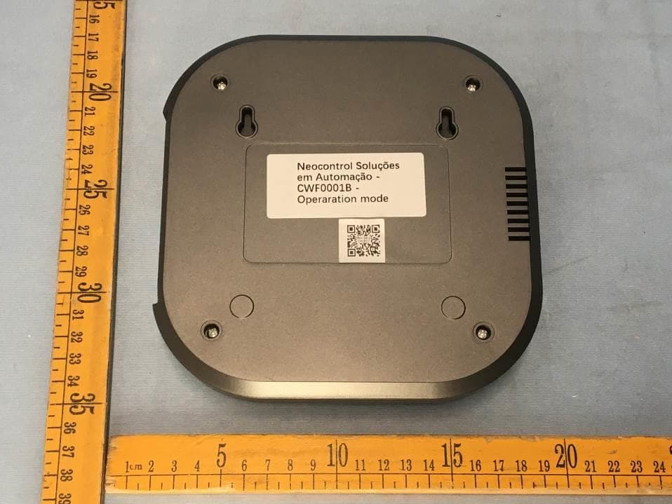
Appendix-CWF0001B-Photos Page 3 of 9 EUT – External View Model CWF0001B FCC ID: 2ALP4-CWF0001B Appendix-CWF0001B-Photos Page 4 of 9 Appendix-CWF0001B-Photos Page 5 of 9
ID Label/Location Info
CWF0001B Label Sample and Location
Internal Photos
Appendix-CWF0001B-Photos Page 6 of 9 EUT – Internal View Model CWF0001B FCC ID: 2ALP4-CWF0001B BT&WIFI modle. Appendix-CWF0001B-Photos Page 7 of 9 433.92 ANT. Appendix-CWF0001B-Photos Page 8 of 9 Appendix-CWF0001B-Photos Page 9 of 9 ======End======
Test Report
Waltek Services (Shenzhen) Co.,Ltd. http://www.waltek.com.cn Page 1 of 22 TEST REPORT Reference No. .................... : WTF19S12085922W001 V1 FCC ID ................................ : 2ALP4-CWF0001B Applicant ............................ : Neocontrol US LLC Address .............................. : 3259, Progress Drive – Room 166 Orlando FL 32826 USA Manufacturer .................... : Neocontrol US LLC Address .............................. : 3259, Progress Drive – Room 166 Orlando FL 32826 USA Product ............................... : Box 98 Model(s). ............................ : CWF0001B Standards........................... : FCC CFR47 Part 15 Section 15.231 Date of Receipt sample .... : 2019-12-10 Date of Test ....................... : 2019-12-11 to 2019-12-19 Date of Issue ...................... : 2019-12-31 Test Result ......................... : Pass Remarks: The results shown in this test report refer only to the sample(s) tested, this test report cannot be reproduced, except in full, without prior written permission of the company. The report would be invalid without specific stamp of test institute and the signatures of compiler and approver. Prepared By: Waltek Services (Shenzhen) Co., Ltd. Address: 1/F., Fukangtai Building, West Baima Road, Songgang Street, Baoan District, Shenzhen, Guangdong, China Tel :+86-755-83551033 Fax:+86-755-83552400 Compiled by: Approved by: Ford Wang / Test Engineer Philo Zhong / Manager Reference No.: WTF19S12085922W001 V1 Page 2 of 22 Waltek Services (Shenzhen) Co.,Ltd. http://www.waltek.com.cn 2 Contents Page 1 COVER PAGE ...................................................................................................................................... 1 2 CONTENTS ............................................................................................................................................................ 2 3 REVISION HISTORY ............................................................................................................................................ 3 4 GENERAL INFORMATION .................................................................................................................................. 4 4.1 GENERAL DESCRIPTION OF E.U.T ............................................................................................................. 4 4.2 DETAILS OF E.U.T ...................................................................................................................................... 4 5 EQUIPMENT USED DURING TEST .................................................................................................................. 5 5.1 EQUIPMENTS LIST ...................................................................................................................................... 5 5.2 MEASUREMENT UNCERTAINTY ................................................................................................................... 5 5.3 SUBCONTRACTED ....................................................................................................................................... 5 6 TEST SUMMARY .................................................................................................................................................. 7 7 CONDUCTED EMISSION .................................................................................................................................... 8 7.1 E.U.T. OPERATION .................................................................................................................................... 8 7.2 EUT SETUP ................................................................................................................................................ 8 7.3 MEASUREMENT DESCRIPTION ................................................................................................................... 8 7.4 CONDUCTED EMISSION TEST RESULT ....................................................................................................... 9 8 RADIATED SPURIOUS EMISSIONS ............................................................................................................... 11 8.1 EUT OPERATION ...................................................................................................................................... 11 8.2 TEST SETUP ............................................................................................................................................. 12 8.3 SPECTRUM ANALYZER SETUP ................................................................................................................. 13 8.4 TEST PROCEDURE .................................................................................................................................... 14 8.5 SUMMARY OF TEST RESULTS .................................................................................................................. 15 9 PERIODIC OPERATION .................................................................................................................................... 16 10 20DB BANDWIDTH ............................................................................................................................................ 20 10.1 TEST PROCEDURE .................................................................................................................................... 20 10.2 TEST RESULT ........................................................................................................................................... 20 11 ANTENNA REQUIREMENT .............................................................................................................................. 21 12 PHOTOGRAPHS OF TEST SETUP AND EUT. .............................................................................................. 22 Reference No.: WTF19S12085922W001 V1 Page 3 of 22 Waltek Services (Shenzhen) Co.,Ltd. http://www.waltek.com.cn 3 Revisi…
Text truncated - open the document above for the full version.
Test Setup Photos
Appendix-CWF0001B-Photos Page 1 of 9 Photographs –Constructional Details Transmitter Setup photo Model CWF0001B FCC ID: 2ALP4-CWF0001B Photograph - Spurious Emissions Radiated Test Setup Below 30MHz Test Site 2# For 30MHz-1000MHz Test Site 2# Appendix-CWF0001B-Photos Page 2 of 9 For Above 1GHz Test Site 1#
Contact Information
Applicant
GABRIEL VALADARES RODRIGUES(COO)
Test Firm
WALTEK TESTING GROUP CO., LTD.Joy Zhou
[email protected]0769-22676998
Technical Specifications
| # | Rule Parts | Frequency Range | Power Output |
|---|---|---|---|
| 1 | 15.231 | 433.92 MHz - 433.92 MHz | - |
Other Applications from NEOCONTROL US LLC
2ALP4-CWF0001B2
Sep 26, 2020Wireless remote control box
Equipment Class
DSC - Part 15 Security/Remote Control Transmitter2ALP4-NMI01WTV2
Jan 05, 2020Slim Touch
Equipment Class
DSC - Part 15 Security/Remote Control Transmitter