2ALSZ-CL31007PPhotocontroller
CIMCON Lighting, Inc.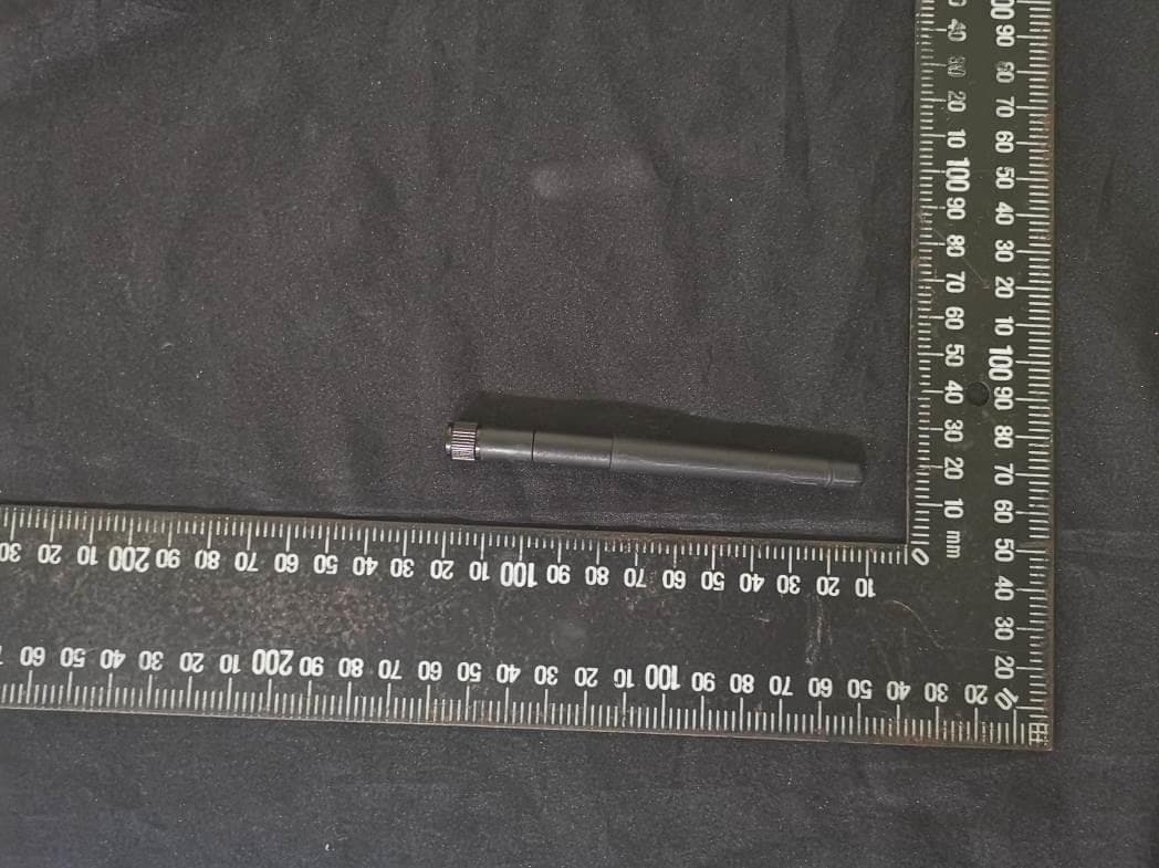
Click to zoom
Application Details
- Equipment Class
- DTS - Digital Transmission System
- Date of Grant
- May 26, 2020
- Application Purpose
- Original Equipment
- Date of Application
- May 20, 2020
- Equipment Note
- Photocontroller
- Frequency Range
- 2405.00000000 - 2475.00000000
- Company
- CIMCON Lighting, Inc.
- Country
- United States
Documents & Files
Document Text
Text extracted from the exhibit documents filed with the FCC. Open a document above to read the original.
Users Manual
Installation and Commissioning Procedure For iSLC3100-7P CIMCON Lighting, Inc. ISLC3100-7P Overview: CIMCON’s iSLC-3100-7P is an intelligent wireless lighting controller with exceptional fault tolerance and a multitude of features. Each iSLC-3100-7P provides intelligent on/off switching, dimming control, GPS, highly accurate power metering, analog and digital sensor inputs and constant status and health monitoring of your lighting fixtures. Each CIMCON iSLC-3100-7P is a highly intelligent stand-alone device that utilizes the latest developments in self- organizing, self-healing, wireless technologies. Proper operation and execution of a light’s schedule is not dependent on network communications. Details installation and commissioning procedure is provided in subsequent sections. RF Radio Zigbee 2.4GHz Specification: CIMCON’s iSLC-3100-7P is having Zigbee 2.4Ghz radio for the wireless network connection, with the below specification. • 2.4 GHz, IEEE 802.15.4 RF • Data Rate: 250 kbps • Receiver Sensitivity: -104 dBm • Transmit Power: +20 dBm • Open Field Range: 5000 ft/1.5 km • Network Type: Self-forming mesh network • Network Fault Tolerance: Self-healing mesh • Data Protection: 256-bit AES encrypt • Hardware: IEEE 802.15.4-2003 CS MA-CA algorithm3 • Operational channel: Channel 11 to 25 • 2.4GHz Zigbee radio produces an O-QPSK-modulated signal using the analog front end and digital baseband. Page 1 Installation Procedure ISLC3100-7P Details installation and commissioning procedure: Place the Photocontroller into the 7-pin NEMA receptacle and rotate it clockwise to lock. Fig. 1 Installation of ISLC3100-7P on the luminaire Page 2 Installation Procedure ISLC3100-7P Fig. 2: Installation wiring diagram Page 3 Installation Procedure ISLC3100-7P The cables protruding from the receptacle have following function as mentioned into table. Once the Photo-controller is installed and luminaire is powered ON then depending on the daylight condition Lamp will operate. In the Lab environment, you can just cover the cap with cloth or by hand and see the Lamp turning ON if wired correctly and if you remove the cloth, it will turn OFF. Safety Consideration for the Installation crew: • Ensure that the supply voltage matches the SLC’s voltage rating. • Firmly place the SLC into the NEMA twist lock receptacle/socket on top of the fixture by aligning the large prong on the SLC with the large opening in the receptacle/socket. Push down on SLC and twist clockwise until it locks into place. • PHOTOCONTROL MUST BE LOCKED IN! Note: window or arrow on top of SLC should be pointed away from the mounting surface. The receptacle/socket may be repositioned by loosening the screw in Page 4 Installation Procedure ISLC3100-7P the center of the receptacle/socket. Rotate to the new position and retighten screw. Do not rotate receptacle/socket over 360 degrees because you can twist receptacle/socket wires. Eventually stripping the insulation and cause the fixture to fail. • To check operation during the daylight hours, cover the SLC’s photocell window (or top surface) completely to simulate darkness. FCC Warning statement: This device complies with Part 15 of the FCC Rules. Operation is subject to the following two conditions: (1) this device may not cause harmful interference, and (2) this device must accept any interference received, including interference that may cause undesired operation. Any changes or modifications not expressly approved by the party responsible for compliance could void the authority to operate equipment. This device and its antenna must not be co- located or operating in conjunction with any other antenna or transmitter. End-users and installers must be provided with antenna installation instructions and transmitter operating conditions for satisfying RF exposure compliance. For product available in the USA/Canada market, only channel 11~25 can be operated. Selection of other channels is not possible This equipment has been tested and found to comply with the limits for a Class B digital device, pursuant to part 15 of the FCC Rules. These limits are designed to provide reasonable protection against harmful interference in a residential installation. This equipment generates uses and can radiate radio frequency energy and, if not installed and used in accordance with the instructions, may cause harmful interference to radio communications. However, there is no guarantee that interference will not occur in a particular installation. If this equipment does cause harmful interference to radio or television reception, which can be determined by turning the equipment off and on, the user is encouraged to try to correct the interference by one or more of the following measures: —Reorient or relocate the receiving antenna. —Increase the separation between the equipment and receiver. —Connect the equipment into an outlet on a circuit different from that to which the receiver is connected. —Consult the dealer or an experienced radio/TV technician for help. 15.19 Page 5 Installation Procedure ISLC3100-7P FCC RF Radiation Exposure Statement: Mobile Device This equipment complies with FCC radiation exposure limits set forth for an uncontrolled environment. This equipment should be installed and operated with minimum distance 20cm between the radiator & your body. Canada (IC) statement: Labeling requirements for Industry Canada are similar to those of the FCC. A clearly visible label on the outside of the final product enclosure must display the following text: IC: 22787-CL3100Z7 RSS-Gen Issue 4 8.4 This device complies with Industry Canada’s licence-exempt RSSs. Operation is subject to the following two conditions: (1) This device may not cause interference; and (2) This device must accept any interference, including interference that may cause undesired operation of the device. Le présent appareil est conforme aux CNR d'Industrie Canada applicables aux appareils radio exempts de licence. L'exploita…
Text truncated - open the document above for the full version.
Cover Letter(s)
RF_160, Issue 04 Applicant Company Name Declaration of Authorization We Name: CIMCON Lighting, Inc. Address: 200 Summit Drive, Suite 500, South Tower City: Burlington Country: United States Declare that: Name Representative of agent: Ms. Melody Wu Agent Company name: BTL Inc. Address: 4F,No.18, Ln. 171, Sec. 2, Jiuzong Rd., Neihu Dist.114, City: Taipei Country Taiwan is authorized to apply for Certification of the following product(s): Product description: Photocontroller Type designation: iSLC3100-7P Trademark: CIMCON Validity/ expiry date: From April 09, 2020 to April 08, 2021 on our behalf. Date: 2020-04-09 City: Burlington Name: Sudhanshu Jha Function: General Manager Signature: Notes: (1): Required for FCC application (2): For FCC it must be the Grantee Code “owner” or the authorized agent.
Cover Letter(s)
FCC, Request for non-disclosure Date: 21-Nov-2018 RF_501, Issue 8 Page 1 of 1 Company Name: CIMCON Lighting, Inc. Address: 200 Summit Drive, Suite 500, South Tower City: Burlington Country: United States To: Telefication B.V., Dept. FCC TCB Edisonstraat 12A 6902 PK ZEVENAAR The Netherlands Subject: Request for confidentiality FCC ID: 2ALSZ-CL31007P Reference number: Dear FCC TCB, 1. Long-Term Confidentiality Pursuant to 47 CFR Section 0.459(a) & (b), we hereby requests non-disclosure and confidential treatment of the following materials submitted in support of FCC certification application: Bill(s) of Material Block Diagrams Operational Description Schematic Diagrams Tune-up Procedure Above materials contain secrets, proprietary and technical information, which would customarily be guarded from competitors under 47 CFR, section 0.457(d)(2). Disclosure or publication or any portion of this company confidential material to other parties could cause substantial competitive harm and provide unjustified benefits for competitors. 2. Short-Term Confidentiality (STC) Pursuant to Public Notice DA 04-1705 of the Commission’s policy, in order to comply with the marketing regulations in 47 CFR §2.803 and the importation rules in 47 CFR §2.1204, applicant hereby requests Short-Term Confidential treatment of the following materials (See notes below): Internal Photos User’s Manual Test Set-up Photos External Photos Justification: Date: 2020-04-15 Name and signature of applicant: Sudhanshu Jha Notes: 1) A document or type of document can only have ONE type of confidentiality! 2) Short-Term confidentiality is in principle for 45 days from date of grant; it can be extended max 3 times (total time 180 days max.)! The planned date should stated in the RF731 application form. 3) FCC must be informed when marketing begins earlier. 4) Release takes place automatically thus extension must be requested in time. Telefication does not remind you of this! 5) Request for extension or for release must be received by Telefication at least 7 days before date of actual marketing or before expiration of the STC period
External Photos
Appendix No.: EP-2002T145-1 APPENDIX-EUT PHOTOS Project No.: 2002T145 Page 1 of 10 Appendix No.: EP-2002T145-1 APPENDIX-EUT PHOTOS Project No.: 2002T145 Page 2 of 10 Appendix No.: EP-2002T145-1 APPENDIX-EUT PHOTOS Project No.: 2002T145 Page 3 of 10 Appendix No.: EP-2002T145-1 APPENDIX-EUT PHOTOS Project No.: 2002T145 Page 4 of 10
ID Label/Location Info
Product Labeling Model: ISLC3100-7P 1. Product Sr. Number Label 2. FCC ID label application 3. Product Model no. / Electrical rating label application 4. MAC ID
Internal Photos
Appendix No.: EP-2002T145-1 APPENDIX-EUT PHOTOS Project No.: 2002T145 Page 5 of 10 Appendix No.: EP-2002T145-1 APPENDIX-EUT PHOTOS Project No.: 2002T145 Page 6 of 10 Appendix No.: EP-2002T145-1 APPENDIX-EUT PHOTOS Project No.: 2002T145 Page 7 of 10 Appendix No.: EP-2002T145-1 APPENDIX-EUT PHOTOS Project No.: 2002T145 Page 8 of 10 Appendix No.: EP-2002T145-1 APPENDIX-EUT PHOTOS Project No.: 2002T145 Page 9 of 10 Appendix No.: EP-2002T145-1 APPENDIX-EUT PHOTOS Project No.: 2002T145 Page 10 of 10
RF Exposure Info
Report No.: BTL-FCCP-2-2002T145 Report Version: R00 Project No.: 2002T145 Page 1 of 2 Maximum Permissible Exposure Report FCC ID: 2ALSZ-CL31007P Report No. : BTL-FCCP-2-2002T145 Equipment : Photocontroller Model Name : iSLC3100-7P-C Brand Name : CIMCON Applicant : CIMCON Lighting, Inc. Address : 200 Summit Drive, Suite 500, South Tower, Burlington, MA 01803 Manufacturer : CIMCON Lighting, Inc. Address : 200 Summit Drive, Suite 500, South Tower, Burlington, MA 01803 According : FCC Guidelines for Human Exposure IEEE C95.1 Date of Receipt : 2020/3/2 Date of Test : 2020/3/2~ 2020/4/7 Issued Date : 2020/4/8 The above equipment has been tested and found in compliance with the requirement of the above standards by BTL Inc. Prepared by : Peter Chen, Engineer Approved by : Scott Hsu , Manager BTL Inc. No.18, Ln. 171, Sec. 2, Jiuzong Rd., Neihu Dist., Taipei City 114, Taiwan Tel: +886-2-2657-3299 Fax: +886-2-2657-3331 Web: www.newbtl.com Report No.: BTL-FCCP-2-2002T145 Report Version: R00 Project No.: 2002T145 Page 2 of 2 MPE CALCULATION METHOD: Calculation Method of RF Safety Distance: where: S = power density P = power input to the antenna G = power gain of the antenna in the direction of interest relative to an isotropic radiator R = distance to the center of radiation of the antenna Table for Filed Antenna: Ant. Brand Model Type Connector Gain (dBi) 1 N/A iSLC3100-7P Monopole N/A 1.5 TEST RESULTS Frequency (MHz) Maximum Conducted Output Power (dBm) Maximum Conducted Output Power (mW) Antenna Gain (dBi) Antenna Gain (numeric) Power Density (S) (mW/cm 2 ) Limit of Power Density (S) (mW/cm 2 ) 2440 22.44 175.3881 1.5 1.4125 0.0493 1.0000 NOTE: The calculated distance is 20 cm. End of Test Report
Test Report
Report No.: BTL-FCCP-1-2002T145 Project No.: 2002T145 Page 1 of 52 Report Version: R02 FCC Radio Test Report FCC ID: 2ALSZ-CL31007P Report No. : BTL-FCCP-1-2002T145 Equipment : Photocontroller Model Name : iSLC3100-7P Brand Name : CIMCON Applicant : CIMCON Lighting, Inc. Address : 200 Summit Drive, Suite 500, South Tower, Burlington, MA 01803 Manufacturer : CIMCON Lighting, Inc. Address : 200 Summit Drive, Suite 500, South Tower, Burlington, MA 01803 Radio Function : ZigBee FCC Rule Part(s) : FCC Part15, Subpart C (15.247) Measurement Procedure(s) : ANSI C63.10-2013 Date of Receipt : 2020/3/2 Date of Test : 2020/3/2~ 2020/4/7 Issued Date : 2020/5/12 The above equipment has been tested and found in compliance with the requirement of the above standards by BTL Inc. Prepared by : Peter Chen, Engineer Approved by : Scott Hsu , Manager BTL Inc. No.18, Ln. 171, Sec. 2, Jiuzong Rd., Neihu Dist., Taipei City 114, Taiwan Tel: +886-2-2657-3299 Fax: +886-2-2657-3331 Web: www.newbtl.com Report No.: BTL-FCCP-1-2002T145 Project No.: 2002T145 Page 2 of 52 Report Version: R02 Declaration BTL represents to the client that testing is done in accordance with standard procedures as applicable and that test instruments used has been calibrated with standards traceable to international standard(s) and/or national standard(s). BTL's reports apply only to the specific samples tested under conditions. It is manufacture’s responsibility to ensure that additional production units of this model are manufactured with the identical electrical and mechanical components. BTL shall have no liability for any declarations, inferences or generalizations drawn by the client or others from BTL issued reports. The report must not be used by the client to claim product certification, approval, or endorsement by NIST, A2LA, or any agency of the U.S. Government. This report is the confidential property of the client. As a mutual protection to the clients, the public and ourselves, the test report shall not be reproduced, except in full, without our written approval. BTL’s laboratory quality assurance procedures are in compliance with the ISO/IEC 17025 requirements, and accredited by the conformity assessment authorities listed in this test report. BTL is not responsible for the sampling stage, so the results only apply to the sample as received. The information, data and test plan are provided by manufacturer which may affect the validity of results, so it is manufacturer’s responsibility to ensure that the apparatus meets the essential requirements of applied standards and in all the possible configurations as representative of its intended use. Limitation For the use of the authority's logo is limited unless the Test Standard(s)/Scope(s)/Item(s) mentioned in this test report is (are) included in the conformity assessment authorities acceptance respective. Please note that the measurement uncertainty is provided for informational purpose only and are not use in determining the Pass/Fail results. Report No.: BTL-FCCP-1-2002T145 Project No.: 2002T145 Page 3 of 52 Report Version: R02 CONTENTS REPORT ISSUED HISTORY 5 1 SUMMARY OF TEST RESULTS 6 1.1 TEST FACILITY 7 1.2 MEASUREMENT UNCERTAINTY 7 1.3 TEST ENVIRONMENT CONDITIONS 8 1.4 TABLE OF PARAMETERS OF TEXT SOFTWARE SETTING 8 1.5 DUTY CYCLE 9 2 GENERAL INFORMATION 10 2.1 DESCRIPTION OF EUT 10 2.2 TEST MODES 11 2.3 BLOCK DIAGRAM SHOWING THE CONFIGURATION OF SYSTEM TESTED 12 2.4 SUPPORT UNITS 12 3 AC POWER LINE CONDUCTED EMISSIONS TEST 13 3.1 LIMIT 13 3.2 TEST PROCEDURE 13 3.3 DEVIATION FROM TEST STANDARD 13 3.4 TEST SETUP 14 3.5 TEST RESULT 14 4 RADIATED EMISSIONS TEST 15 4.1 LIMIT 15 4.2 TEST PROCEDURE 16 4.3 DEVIATION FROM TEST STANDARD 16 4.4 TEST SETUP 17 4.5 EUT OPERATING CONDITIONS 18 4.6 TEST RESULT – 30 MHZ TO 1 GHZ 18 4.7 TEST RESULT – ABOVE 1 GHZ 18 5 BANDWIDTH TEST 19 5.1 APPLIED PROCEDURES / LIMIT 19 5.2 TEST PROCEDURE 19 5.3 DEVIATION FROM STANDARD 19 5.4 TEST SETUP 19 5.5 EUT OPERATION CONDITIONS 19 5.6 TEST RESULTS 19 6 OUTPUT POWER TEST 20 6.1 APPLIED PROCEDURES / LIMIT 20 6.2 TEST PROCEDURE 20 6.3 DEVIATION FROM STANDARD 20 6.4 TEST SETUP 20 6.5 EUT OPERATION CONDITIONS 20 6.6 TEST RESULTS 20 7 POWER SPECTRAL DENSITY TEST 21 7.1 APPLIED PROCEDURES / LIMIT 21 7.2 TEST PROCEDURE 21 7.3 DEVIATION FROM STANDARD 21 7.4 TEST SETUP 21 7.5 EUT OPERATION CONDITIONS 21 7.6 TEST RESULTS 21 Report No.: BTL-FCCP-1-2002T145 Project No.: 2002T145 Page 4 of 52 Report Version: R02 8 ANTENNA CONDUCTED SPURIOUS EMISSION 22 8.1 APPLIED PROCEDURES / LIMIT 22 8.2 TEST PROCEDURE 22 8.3 DEVIATION FROM STANDARD 22 8.4 TEST SETUP 22 8.5 EUT OPERATION CONDITIONS 22 8.6 TEST RESULTS 22 9 LIST OF MEASURING EQUIPMENTS 23 10 EUT TEST PHOTO 25 11 EUT PHOTOS 25 APPENDIX A AC POWER LINE CONDUCTED EMISSIONS 26 APPENDIX B RADIATED EMISSIONS - 30 MHZ TO 1 GHZ 29 APPENDIX C RADIATED EMISSIONS - ABOVE 1 GHZ 32 APPENDIX D BANDWIDTH 44 APPENDIX E OUTPUT POWER 46 APPENDIX F POWER SPECTRAL DENSITY TEST 48 APPENDIX G ANTENNA CONDUCTED SPURIOUS EMISSION 50 Report No.: BTL-FCCP-1-2002T145 Project No.: 2002T145 Page 5 of 52 Report Version: R02 REPORT ISSUED HISTORY Report Version Description Issued Date R00 Original Issue. 2020/4/8 R01 Update duty cycle data. 2020/5/8 R02 Revised Typo. 2020/5/12 Report No.: BTL-FCCP-1-2002T145 Project No.: 2002T145 Page 6 of 52 Report Version: R02 1 SUMMARY OF TEST RESULTS Test procedures according to the technical standards. FCC Part 15, Subpart C (15.247) Standard(s) Section Description Test Result Judgement Remark 15.207 AC Power Line Conducted Emissions APPENDIX A Pass ------ 15.205 15.209 15.247(d) Radiated Emissions APPENDIX B APPENDIX C Pass ------ 15.247(a)(2) Bandwidth APPENDIX D Pass ------ 15.247(b)(3) Output Power APPENDIX E Pass ------ 15.247(e) Power Spectral Density APPENDIX F Pass ------ 15.247(d) Antenna conducted Spurious Emission APPENDIX G Pass ------ 15.203 Antenna Requirement ------ Pass ------ NOTE: (1) ”N/A” denotes test is not applicable in this Test Re…
Text truncated - open the document above for the full version.
Test Setup Photos
Appendix No.: TP-2002T145-1 APPENDIX-TEST PHOTOS Project No.: 2002T145 Page 1 of 3 AC Power Line Conducted Emissions test photos Appendix No.: TP-2002T145-1 APPENDIX-TEST PHOTOS Project No.: 2002T145 Page 2 of 3 Radiated Emissions test photos 30 MHz to 1 GHz Appendix No.: TP-2002T145-1 APPENDIX-TEST PHOTOS Project No.: 2002T145 Page 3 of 3 Radiated Emissions test photos Above 1 GHz
Contact Information
Applicant
Sudhanshu Jha(General Manager)
Technical Contact
Non-Technical Contact
BTL Inc.Melody Wu
[email protected]886-2-2641-8198
Test Firm
BTL Inc.Jackie Chiu
Technical Specifications
| # | Rule Parts | Frequency Range | Power Output |
|---|---|---|---|
| 1 | 15C | 2.40 GHz - 2.48 GHz | 180.00 mW |
Other Applications from CIMCON Lighting, Inc.

2ALSZ-CL3100N
Jan 27, 2021Photocontroller
Equipment Class
PCB - PCS Licensed Transmitter