2ALZL-AA24002.1 Computer Multimedia Speaker
Goldwood Sound, Inc.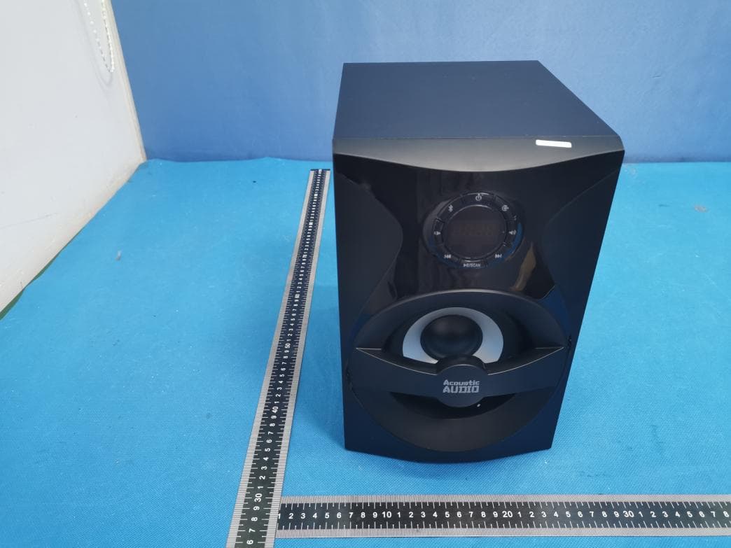
Click to zoom
Application Details
- Equipment Class
- DSS - Part 15 Spread Spectrum Transmitter
- Date of Grant
- Oct 22, 2020
- Application Purpose
- Original Equipment
- Date of Application
- Oct 22, 2020
- Equipment Note
- 2.1 Computer Multimedia Speaker
- Frequency Range
- 2402.00000000 - 2480.00000000
- Company
- Goldwood Sound, Inc.
- Country
- United States
Documents & Files
Document Text
Text extracted from the exhibit documents filed with the FCC. Open a document above to read the original.
Users Manual
2. FM source: directly press numeric keys through remote to select your favorite station if you know the station number (1~100). Or press 3 or 4 digits of frequency to play that station, for example, 1026 for 102.6 MHz station. K. Play/Pause: USB/SD and BT source, short press to play or pause. L. Prev: USB/SD and BT source, short press to select previous song. M. Next: USB/SD and BT source, short press to select next song. N. Folder / : USB/SD source, short press to select next/previous folder. O .:Short press for Bluetooth mode. To enter pairing mode, long press and the display with flash quickly P. Reset: short press to go to default settings. A.: Turn on/off unit. B.: Inse rt the satellite speaker cables into Audio Output terminals in the back of the subwoofer D .: Switch between BT, AUX, USB/SD and FM mode. E. (1). USB/SD Mode: short press for play/pause music. (2). FM Mode: Short press to start Auto Search & this will store the found frequencies (channels) automatically. (3). Bluetooth mode:short press to play/pause music. F . (1). USB/SD mode: Short press to select previous song and long press to select previous folder. (2). FM mode: Short press to select previous stored station. (3). Bluetooth mode: short press to select previous song. Function of Panel keys Front panel keys 1.Standby button 2.Bluetooth button 3.Volume decrease button 4.Previous/CH- button 5.Source button 6.Volume increase button 7.Next/CH+ button 8.Play/Pause/FM auto scan button G. (1). USB/SD mode: Short press to select next song and long press to select next folder. (2). FM mode: Short press to select next stored station. (3). Bluetooth mode: short press to select next song. Remote control Remote control keys function A.: tu rn on/off unit. B. AUX, ,USB (For USB /SD Mode) and FM key: short press the keys to switch to respective modes. C. : press it to mute or unmute the sound. D .: inc rease or decrease master volume. E. Tune+/-: FM mode: Fine Tuning: Short press to increase or decrease one step . Manual Tuning: Long press of this key works for Manual tuning. F. MEM: Short press of this key work to store tuned station through Fine or Manual tuning. G. CH+/-:FM mode: select stored station. H. Scan: FM mode: Short press to start Auto Search & this will store the found f requencies (channels) automatically. I. Enter: confirm selection and return to main screen. J . Light:Short press to turn on/off the lights. K. 0~9 number keys: 1. USB/SD sou rce: directly press numeric keys through remote to select your favorite song if you know the song number in the folder.The system will automatically play the last song of the folder if you press number excess of song number of that folder. Warning: Changes or modifications to this unit not expressly approved by the party responsible for compliance could void the user’ NOTE: This equipment has been tested and found to comply with the limits for a Class B digital device, pursuant to Part 15 of the FCC Rules. These limits are designed to provide reasonable protection against harmful interference in a residential installation. This equipment generates, uses and can radiate radio frequency energy and, if not installed and used in accordance with the instructions, may cause harmful interference to radio communications. However, there is no guarantee that interference will not occur in a particular installation. If this equipment does cause harmful interference to radio or television reception, which can be determined by turning the equipment off and on, the user is encouraged to try to correct the interference by one or more of the following measures: Reorient or relocate the receiving antenna. Increase the separation between the equipment and receiver. Connect the equipment into an outlet on a circuit different from that to which the receiver is connected. Consult the dealer or an experienced radio/TV technician for help. This device complies with Part 15 of the FCC Rules. Operation is subject to the following two conditions: (1) this device may not cause harmful interference, and (2) this device must accept any interference received, including interference that may cause undesired operation. RF Exposure Statement To maintain compliance with FCC’ minimum distance between 20cm the radiator your body: Use only the supplied antenna. 1.Turn on the system 2.Press "Source" on the remote or front panel 3.Find Bluetooth mode, once in bluetooth mode the LED will blink while searching for bluetooth devices. 4.Turn on your bluetooth device and search for "AA2400 " in the devices list 5.Press connect, once connected the LED will stop blinking. 6.You can now play music from your bluetooth device. Please do not dispose of this product in the garbage. Doing this is harmful to your environment. Please drop off at a loal recycling center for disposal. Output Power(RMS):108W=56W+26W*2 Speaker Unit: Satellite: 3” Subwoofer: 5.25” Power Supply: 120V~60Hz 0.4A Frequency Response: Satellite: 110Hz~20KHz Subwoofer: 30Hz~90Hz S/N Ratio: ≥70dB Separation: ≥40dB AA2400 2.1 Do not place the system in a high temperature or humid environment. Prevent the system from wetness or rough handling If a foreign object or liquid accidentally enters the speaker system, turn off the power immediately and contact the dealer Turn off the power and unplug the system when not in use Insert the satellite speaker cables into Audio Output terminals in the back of the subwoofer Innovative, colorful LED brightens the lis tening experience. Built in OCL Amplif ier provides a super bass design for the subwoofer with 3 output channels Specifications Bluetooth Connection Instructions: Subwoofer unit s authority to operate the equipment. s RF Exposure guidelines, This equipment should be installed and operated with
External Photos
S20091601602 Model: AA2400 Photo 1 Photo 2 S20091601602 Model: AA2400 Photo 3 Photo 4 S20091601602 Model: AA2400 Photo 5 Photo 6 S20091601602 Model: AA2400 Photo 7 Photo 8 S20091601602 Model: AA2400 Photo 9
ID Label/Location Info
6mm 6mm 429C MODEL NO.:AA2400 FCC ID:2ALZL-AA2400 Made in China This device complies with Part 15 of the FCC Rules. Operation is subject to the following two conditions: (1) this device may not cause harmful interference, and (2) this device must accept any interference received, including interference that may cause undesired operation. Label 6mm 6mm MODEL NO.:AA2400 FCC ID:2ALZL-AA2400 Made in China This device complies with Part 15 of the FCC Rules. Operation is subject to the following two conditions: (1) this device may not cause harmful interference, and (2) this device must accept any interference received, including interference that may cause undesired operation. Location
Internal Photos
S20091601602 Model: AA2400 Photo 1 Photo 2 S20091601602 Model: AA2400 Photo 3 Photo 4 S20091601602 Model: AA2400 Photo 5 Photo 6 BT ANT S20091601602 Model: AA2400 Photo 7 Photo 8 S20091601602 Model: AA2400 Photo 9 Photo 10 S20091601602 Model: AA2400 Photo 11 Photo 12 S20091601602 Model: AA2400 Photo 13
RF Exposure Info
FCC ID: 2ALZL-AA2400 RF EXPOSURE EVALUATION According to FCC 1.1310: The criteria listed in the following table shall be used to evaluate the environment impact of human exposure to radio frequency(RF) Radiation as specified in §1.1307(b) Limits for Maximum Permissible Exposure (MPE) MPE Calculation Method E (V/m) = d GP**30 Power Density: Pd (W/m²) = 377 2 E E = Electric field (V/m) P = Average RF output power (W) G = EUT Antenna numeric gain (numeric) d = Separation distance between radiator and human body (m) The formula can be changed to Pd = 2 *377 **30 D GP From the EUT RF output power, the minimum mobile separation distance, d=0.2m, as well as the gain of the used antenna, the RF power density can be obtained. MAX OUTPUT POWER BR+EDR Measurement Result Operation Frequency: BT: 2402-2480MHz Power density limited: 1mW/ cm 2 Antenna Type: PCB Antenna Antenna gain: 3dBi, R=20cm conducted power Evaluation result Power density Limits (dBm)(mW)(dBi)Numeric 2402 -5.95 -5±1-4 0.3983.002.000.00021 2441 -4.96 -5±1-4 0.3983.002.000.00021 2480 -5.27 -5±1-4 0.3983.002.000.00021 2402 -3.24 -3±1-2 0.6313.002.000.00031 2441 -3.66 -3±1-2 0.6313.002.000.00031 2480 -3.71 -3±1-2 0.6313.002.000.00031 Channel Freq. (MHz) modulation Tune-up power (dBm) (dBm) π/4-DQPSK (mW/cm2 )(mW/cm2) Antenna Gain GFSK Max tune-up power Conclusion: For the max result : 0.0002≤ 1.0 for Max Power Density, compliance RF exposure.. Signature: Date: 2020-10-15 NAME AND TITLE (Please print or type): Alex Li/Manager COMPANY (Please print or type): Shenzhen NTEK Testing Technology Co., Ltd./ 1/F, Building E, Fenda Science Park, Sanwei Community, Xixiang Street Bao’an District, Shenzhen P.R. China.
Test Report
Report No.: S20091601602001 Version.1.3 Page 1 of 67 RADIO TEST REPORT FCC ID: 2ALZL-AA2400 Product: 2.1 Computer Multimedia Speaker Trade Mark: Acoustic Audio by Goldwood Model No.: AA2400 Family Model: N/A Report No.: S20091601602001 Issue Date: 29 Sep.2020 Prepared for Goldwood Sound, Inc. 9333 Oso Ave.Chatsworth, Chatsworth, CA 91311 Prepared by Shenzhen NTEK Testing Technology Co., Ltd. 1/F, Building E, Fenda Science Park Sanwei, Xixiang, Bao'an District Shenzhen, Guangdong, China Tel.: +86-755-6115 6588 Fax.: +86-755-6115 6599 Website:http://www.ntek.org.cn Report No.: S20091601602001 Version.1.3 Page 2 of 67 TABLE OF CONTENTS 1 TEST RESULT CERTIFICATION ...................................................................................................................... 3 2 SUMMARY OF TEST RESULTS ......................................................................................................................... 4 3 FACILITIES AND ACCREDITATIONS ............................................................................................................. 5 3.1 FACILITIES..................................................................................................................................................... 5 3.2 LABORATORY ACCREDITATIONS AND LISTINGS ................................................................................. 5 3.3 MEASUREMENT UNCERTAINTY ............................................................................................................... 5 4 GENERAL DESCRIPTION OF EUT .................................................................................................................. 6 5 DESCRIPTION OF TEST MODES ..................................................................................................................... 8 6 SETUP OF EQUIPMENT UNDER TEST ........................................................................................................... 9 6.1 BLOCK DIAGRAM CONFIGURATION OF TEST SYSTEM ....................................................................... 9 6.2 SUPPORT EQUIPMENT............................................................................................................................... 10 6.3 EQUIPMENTS LIST FOR ALL TEST ITEMS .............................................................................................. 11 7 TEST REQUIREMENTS .................................................................................................................................... 13 7.1 CONDUCTED EMISSIONS TEST ............................................................................................................... 13 7.2 RADIATED SPURIOUS EMISSION ............................................................................................................ 16 7.3 NUMBER OF HOPPING CHANNEL ........................................................................................................... 25 7.4 HOPPING CHANNEL SEPARATION MEASUREMENT ........................................................................... 26 7.5 AVERAGE TIME OF OCCUPANCY (DWELL TIME) ................................................................................ 27 7.6 20DB BANDWIDTH TEST .......................................................................................................................... 29 7.7 PEAK OUTPUT POWER .............................................................................................................................. 30 7.8 CONDUCTED BAND EDGE MEASUREMENT......................................................................................... 31 7.9 SPURIOUS RF CONDUCTED EMISSION .................................................................................................. 32 7.10 ANTENNA APPLICATION .......................................................................................................................... 33 7.11 FREQUENCY HOPPING SYSTEM (FHSS) EQUIPMENT REQUIREMENTS .............................................. 34 8 TEST RESULTS ................................................................................................................................................... 35 8.1 DWELL TIME ............................................................................................................................................... 35 8.2 MAXIMUM CONDUCTED OUTPUT POWER........................................................................................... 39 8.3 OCCUPIED CHANNEL BANDWIDTH ....................................................................................................... 43 8.4 CARRIER FREQUENCIES SEPARATION .................................................................................................. 47 8.5 NUMBER OF HOPPING CHANNEL ........................................................................................................... 51 8.6 BAND EDGE ................................................................................................................................................. 52 8.7 CONDUCTED RF SPURIOUS EMISSION .................................................................................................. 61 Report No.: S20091601602001 Version.1.3 Page 3 of 67 1 TEST RESULT CERTIFICATION Applicant’s name ......................... : Goldwood Sound, Inc. Address ....................................... : 9333 Oso Ave.Chatsworth, Chatsworth, CA 91311 Manufacturer's Name .................. : SHENZHEN FENDA TECHNOLOGY CO., LTD. Address ....................................... : Fenda Hi-Tech Park, Zhoushi Road, Shiyan Town, Baoan District, Shenzhen City, Guangdong, China Product description Product name .............................. : 2.1 Computer Multimedia Speaker Model and/or type reference ..... : AA2400 Family Model ............................... : N/A Measurement Procedure Used: APPLICABLE STANDARDS STANDARD/ TEST PROCEDURE TEST RESULT FCC 47 CFR Part 2, Subpart J FCC 47 CFR Part 15, Subpart C…
Text truncated - open the document above for the full version.
Test Setup Photos
FCC ID: 2ALZL-AA2400 Radiated Measurement Photos FCC ID: 2ALZL-AA2400 Conducted Measurement Photos
Contact Information
Applicant
Marty Bloom(General Manager)
Technical Contact
Test Firm
Shenzhen NTEK Testing Technology Co., Ltd.Alex Li
[email protected]+86-755-6115-9384
Technical Specifications
| # | Rule Parts | Frequency Range | Power Output |
|---|---|---|---|
| 1 | 15C | 2.40 GHz - 2.48 GHz | 470.00 µW |
Other Applications from Goldwood Sound, Inc.
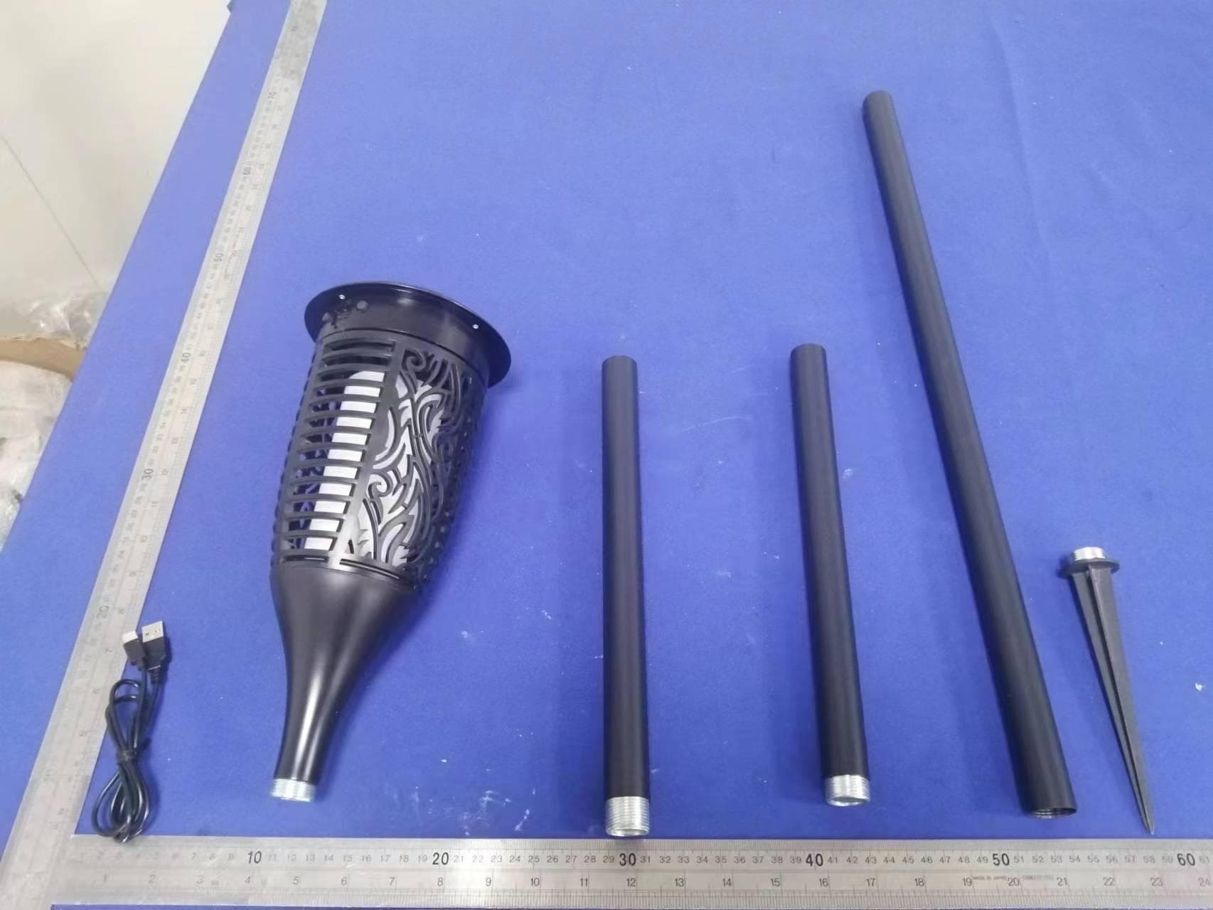
2ALZLTT100TIKITORCH
Jul 05, 2023Tiki Torch Bluetooth Speaker
Equipment Class
DSS - Part 15 Spread Spectrum Transmitter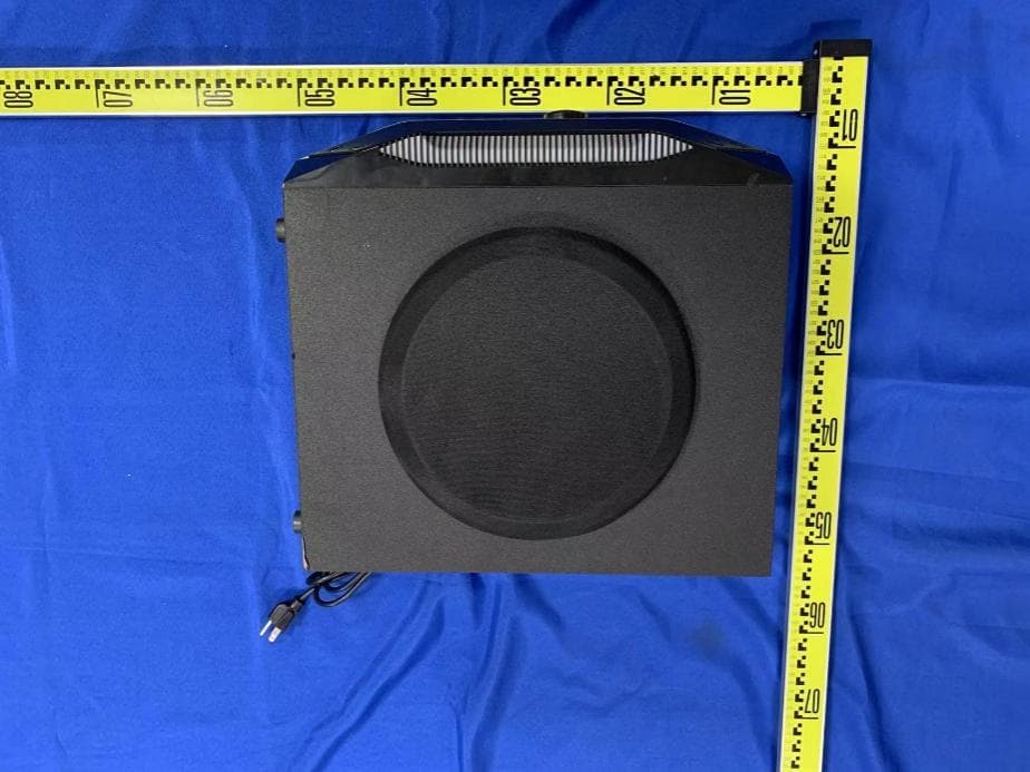
2ALZL-AAT1000
Jul 11, 2022MULTIMEDIA SPEAKER SYSTEM
Equipment Class
DSS - Part 15 Spread Spectrum Transmitter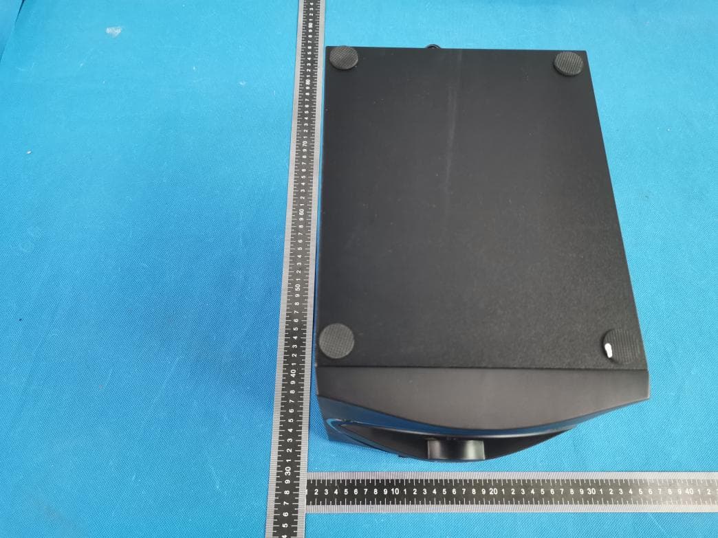
2ALZL-F3800XA
Jan 19, 20215.1 BLUETOOTH MULTIMEDIA SPEAKER SYSTE
Equipment Class
DSS - Part 15 Spread Spectrum Transmitter