2AM3K-SPA-3000BTamplifier
OKURA USA INC.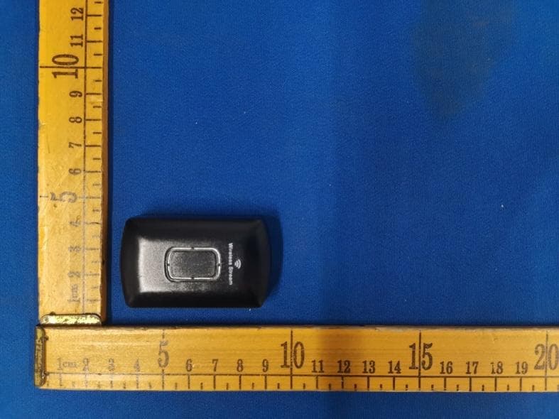
Click to zoom
Application Details
- Equipment Class
- DSS - Part 15 Spread Spectrum Transmitter
- Date of Grant
- Dec 18, 2022
- Application Purpose
- Original Equipment
- Date of Application
- Dec 18, 2022
- Equipment Note
- amplifier
- Frequency Range
- 2402.00000000 - 2480.00000000
- Company
- OKURA USA INC.
- Country
- United States
Documents & Files
Document Text
Text extracted from the exhibit documents filed with the FCC. Open a document above to read the original.
Users Manual
SPA- 3000BT HYBRID DIGITAL RECEIVER AMPLIFIER AUXHEADPHONESMIC1 USB MIC2 PLAY/PAUSE AM/FM PREV< NEXT> AUTO SCAN HYBRID DIGITAL RECEIVER AMPLIFIER INPUT MENU LED A/B SUB.OUT MIC.VOL - + MIC.TONE MASTER VOLUME ECHO TABLE OF CONTENTS Table of contents Foreword 1 1 Features Precautions 2 3 4 5 6 7 8 9 Technical specifications Front panel function Rear panel function Remote device function Safety instructions Bluetooth function Connecting to amplifier FM Antenna 1Piece Remote control One AC Power Cord AM Antenna 1Piece What is Included: One (1) MP3 input cable One (1) USB input cable One (1) bluetooth receiver Two (2) Rack mount brackets with screws One (1) AC Power Cord One (1) MP3 input cable One (1) USB input cable One (1) bluetooth receiver One (1) FM Antenna One (1) AM Antenna Two (2) Rack mount brackets with screws VFD+ 10+ LED AUTODVD/CDTUNERAUXUSB TREBLE+ VFD- BLUETOOTH 7 TUNING+ 3 6 0 FM/PAUSE A DSP1 DSP5 DSP2 DSP6 DSP3 DSP7 DSP4 OFF BA+BLOUD MUTE VOL+ VOL- TUNING- 2 5 9 AM/PLAY ST/MONO 1 4 8 TREBLE- BASS- LR BASS+ MEMORYPREV NEXT — — ▲▲ AUTO SCAN BLUETOOTH FUNCTION BLUETOOTH FUNCTION 1. Connect the bluetooth receiver to Bluetooth receiver input jack on rear panel with the cable. Connection should be done before turn on the amplifier. 2. Turn on the amplifier and select bluetooth input. Active bluetooth function on your mobile or other bluetooth device. Pair it to the bluetooth device named SPA-BT1 then you can play audio on the amplifier via bluetooth. NOTES: 1. Available operation range of Bluetooth function of the unit is 10 meters. Be sure there are no obstacles between the unit and your mobile phone or it will affect the Bluetooth effect then cause the sound brokenly. 2. This operation only available for device with bluetooth function such as mobiles and pad computers. 3. Above operation is based on iPhone 5S. Different bluetooth devices may have different setting and step to play music via bluetooth. Please follow the instruction of your bluetooth device and connect it to this amplifier accordingly. 9 1. Make sure that all connections are properly connected and the main volume is set to minimum level before turning on the unit. 2. When more than one pair of speakers are used, (specially the main speaker output) make sure that the speakers used are of the same wattage and impedance, otherwise the unit maybe damaged under high power or long term operation. 3. To avoid humming sounds and unwanted noise, make sure that all the wires are properly inserted. 4. For speaker cords, strip off the vinyl coating and twist the wire tip. Push down the pink jack or loosen the screw terminal, before inserting the wire tip, then fasten it and tighten the screw. Be careful not to let the wires stick out of the terminal otherwise this may cause a short circuit when wires of different terminal contact each other. 5. After the unit is turned on, adjust the main volume to the desired level same is true with the bass and treble volume, etc. SAFETY INSTRUCTIONS Please read this operating instructions carefully before using. It will acquaint you fully with all its features and help you enjoy your time . The product adopts the most advanced digital technique in the world. It is 4 channels with its high power output, so to speak, the real acoustic centre of your family movie theatre. It is designed to be multi-funtional AM/FM Tuner、MP3/Ipod input jack, headphone input jack. It is a product of the finest accompanying acoustic amplifier, when applied to TUNER,AUX/USB,DVD/CD,BLUETOOTH etc. The brings you the first ever Hybrid Amplifier with designed Sub out and Pre out to adjust to every situation. Thank you for purchasing this fine amplifier. Features Foreword 81 SAFETY INSTRUCTIONS FOREWORD / FEATURES External bluetooth function Powers 4 loudspeakers Separate gain control for preamp and subwoofer Inputs: rca (2 audio sources) Outputs: banana binding post (to speakers) 1 rca dedicated for record line output 2 mono rca dedicated for subwoofer output 1 rca dedicated for preamp output Digital fluorescent output display meter 3.5mm mp3 input with cable 110-220v switchable Am/fm quartz synthesized tuner Auto station seek USB Reader function AUX AUDIO INPUT DVD/CD REC.LINE SUB.OUT PRE.OUT AUDIO OUTPUT CAUTION: TO REDUCE THE RISK OF ELECTRIC SHOCK, DO NOT REMOVE COVER OR BACK. OPENING THIS UNIT WILL VOID WARRANTY. NO USER SHOULD SERVICE ANY PARTS INSIDE. REFER SERVICING TO A QUALIFIED SERVICE PERSONNEL. ! RISK OF ELECTRIC SHOCK DO NOT OPEN WARNING ~230V/50HZ ~115V/60HZ VOLTAGE SELECTOR A B A B COOLING FAN ENGNIEERED IN JAPAN DESIGNED IN THE USA FUSE ~115VT8AH ~230VT5AH BLUETOOTH RECEIVER INPUT 72 1.Power source-The unit should be connected to a power supply AC~110V/60Hz, AC~220V/50Hz. 2.Ventilation-The unit should be situated so that its location or position does not interfere with its proper ventilation. Place the unit at least 10cm away from the walls. 3.Water and moisture-The unit should not be used near water-for example, near a swimming pool in a wet basement, etc. 4.Electric shock-if a metal object, such as hair pin or needle comes into contact inside this unit, a dangerous electric shock may result. For families with children, never permit children to put anything, especially metal, inside this unit. 5.Enclosure removal-Never remove the enclosure. If the internal parts are touched accidentally, a serious electric shock might occur. 6.Abnormal smell-if an abnormal smell or smoke is detected, immediately turn the power OFF and pull out the power cord. Contact your dealer or nearest service station. Precautions PRECAUTIONS CONNECTING TO AMPLIFIER Connecting to amplifier FM ANTENNA AM ANTENNA DVD/CD CD Recorder Power Amp Preamp Out Power Amp 2 Mono Sub Outputs Power Amp 2 MIC INPUTS USB AUX MP3 input (3.5mm) AUX Speaker A (Left) Speaker B (Left) Speaker B (right) Speaker A (right) Play music via bluetooth Bluetooth receiver 6 Remote Control Operation 1. Remote control should be operated within 6 meters and the…
Text truncated - open the document above for the full version.
Cover Letter(s)
Date:2022-12-14 Federal Communications Commission Authorization & Evaluation Division 7345 Oakland Mills Road Columbia, Maryland 21046 RE: LETTER OF AGENT AUTHORIZATION To Whom It May Concern: We, the undersigned, hereby authorize Compliance Testing, LLC to act on our behalf in all matters relating to application for equipment authorization, including the signing of all documents relating to these matters. We also hereby certify that no party to the application authorized hereunder is subject to the denial of benefits, including FCC benefits, pursuant to Section 5301 of the Anti-Drug Abuse Act of 1988, 21 U.S.C.853(a). <Signature> Name: Abe Brach Title: Manage Applicant Company: OKURA USA INC.
Cover Letter(s)
DATE 2022-12-14 Equipment Autorisation Division Federal Communications Commission 7435 Oakland Mills Road Columbia, MD 21046 FCC ID:2AM3K-SPA-3000BT Product Name:amplifier Request for Confidentiality Pursuant to Sections 0.457 and 0.459 of the commissions rules, we hereby request that the following documents be held confidential: (List here the documents for which you are seeking confidentiality – for example ...) Schematics Block diagram Operation description These materials contain trade secrets and proprietary information and are not customarily released to the public. The public disclosure of this information might be harmful to the company and provide unjustified benefits to our competitors. <Signature> Name: Abe Brach Title: Manage Applicant Company: OKURA USA INC.
Cover Letter(s)
DATE:2022-12-14 Federal Communications Commission Authorization & Evaluation Division 7345 Oakland Mills Road Columbia, Maryland 21046 Authority to Act asAgent Onourbehalf,IappointDongguan New Testing Centre Co., Ltd;3F, No. 1 the 1st North Industry Road, Songshan Lake Science &Technology Park, Dongguan, Guangdong, China, 523808. toactasouragentinthepreparationofthisapplicationforequipmentcertification.Icertifythatsubmitte ddocumentsproperlydescribethedeviceorsystemforwhichequipmentcertificationissought.Ialsoc ertifythateachunitmanufactured,importedormarketed,asdefinedintheFederalCommunicationsC ommission’sregulationswillhaveaffixedtoit a label identical to that submitted for approval with thisapplication. Forinstanceswhereourauthorizedagentsignstheapplicationforcertificationonourbehalf,Iack nowledgethatallresponsibilityforcomplyingwiththetermsandconditionsforcertification,stillres ideswith OKURA USA INC.;1195 NW 97 AVENUE, MIAMI, FL33172 U.S.A. <Signature> Name: Abe Brach Title: Manage Applicant Company: OKURA USA INC.
Cover Letter(s)
OKURA USA INC. 1195 NW 97 AVENUE, MIAMI, FL33172 U.S.A. Tel: 305-592-0030 Fax: 305-592-0030 Series Models Description FCC ID: 2AM3K-SPA-3000BT Date: Dec. 14, 2022 Federal Communications Commission Authorization and Evaluation Division 7435 Oakland Mills Road Columbia, MD 21046 To whom it may concern: The device (Product Name: amplifier) Models Name: SPA-3000BT , SPA-2000BT, SPA-5000BT have same electrical, PCB and BOM, only the colour and model’s names are different for marketing requirements. <Signature> Name: Abe Brach Title: Manage Applicant Company: OKURA USA INC.
External Photos
Page 1 of 5 FCC-ID:2AM3K-SPA-3000BT External photos Fig.1 (Model:SPA-3000BT) Fig.2 (Model:SPA-3000BT) Page 2 of 5 FCC-ID:2AM3K-SPA-3000BT Fig.3(Model:SPA-3000BT) Fig.4 (Model:SPA-3000BT) Page 3 of 5 FCC-ID:2AM3K-SPA-3000BT Fig.5(Model:SPA-3000BT) Fig.6 (Model:SPA-3000BT) Page 4 of 5 FCC-ID:2AM3K-SPA-3000BT Fig.7(Model:SPA-3000BT) Fig.8 (Model:SPA-3000BT) Page 5 of 5 FCC-ID:2AM3K-SPA-3000BT Fig.9 (Model:SPA-3000BT)
ID Label/Location Info
Page 1 of 1 FCC-ID:2AM3K-SPA-3000BT Label and label location amplifier Model: SPA-3000BT FCC ID:2AM3K-SPA-3000BT This device complies with part 15 of the FCC Rules. Operation is subject to the following two conditions: (1)This device may not cause harmful interference, and (2) this device must accept any interference received, including interference that may cause undesired operation.
Internal Photos
Page 1 of 12 FCC-ID:2AM3K-SPA-3000BT Internal Photos Fig.10(Model:SPA-3000BT) Fig.11(Model:SPA-3000BT) Page 2 of 12 FCC-ID:2AM3K-SPA-3000BT Fig.12(Model:SPA-3000BT) Page 3 of 12 FCC-ID:2AM3K-SPA-3000BT Fig.13(Model:SPA-3000BT) Fig.14(Model:SPA-3000BT) Page 4 of 12 FCC-ID:2AM3K-SPA-3000BT Fig.15(Model:SPA-3000BT) Fig.16(Model:SPA-3000BT) Page 5 of 12 FCC-ID:2AM3K-SPA-3000BT Fig.17(Model:SPA-3000BT) Fig.18(Model:SPA-3000BT) Page 6 of 12 FCC-ID:2AM3K-SPA-3000BT Fig.19(Model:SPA-3000BT) Fig.20(Model:SPA-3000BT) Page 7 of 12 FCC-ID:2AM3K-SPA-3000BT Fig.21 (Model: SPA-3000BT) Fig.22 (Model: SPA-3000BT) Page 8 of 12 FCC-ID:2AM3K-SPA-3000BT Fig.23 (Model: SPA-3000BT) Fig.24 (Model: SPA-3000BT) Page 9 of 12 FCC-ID:2AM3K-SPA-3000BT Fig.25 (Model: SPA-3000BT) Fig.26 (Model: SPA-3000BT) Page 10 of 12 FCC-ID:2AM3K-SPA-3000BT Fig.27 (Model: SPA-3000BT) Fig.28 (Model: SPA-3000BT) Page 11 of 12 FCC-ID:2AM3K-SPA-3000BT Fig.29 (Model: SPA-3000BT) Fig.30 (Model: SPA-3000BT) BT Antenna Page 12 of 12 FCC-ID:2AM3K-SPA-3000BT Fig.31 (Model: SPA-3000BT)
RF Exposure Info
FCC‐ID:2AM3K‐SPA‐3000BT Page 1 of 1 Report No.: NTC‐ER2210009 RF Exposure Letter According to 447498 D01 General RF Exposure Guidance v05 The 1‐g and 10‐g SAR test exclusion thresholds for 100 MHz to 6 GHz at test separation distances ≤ 50 mm are determined by: [(max. power of channel, including tune‐up tolerance, mW)/(min. test separation distance, mm)] ·[√f(GHz)] ≤ 3.0 for 1‐g SAR and ≤ 7.5 for 10‐g extremity SAR, where f(GHz) is the RF channel transmit frequency in GHz Power and distance are rounded to the nearest mW and mm before calculation The result is rounded to one decimal place for comparison Worse case is as below: [2480 MHz 0.166dBm(1.04 mW) output power] (1.04mW /5mm)·[√2.480(GHz)]= 0.33<3.0 for 1‐g SAR Then SAR evaluation is not required
Test Report
FCC TEST REPORT Report No. ...................................... : NTC-ER2210009 Applicant’s name ........................... : OKURA USA INC. Address .......................................... : 1195 NW 97 AVENUE, MIAMI, FL33172 U.S.A. DONGGUAN NEW TESTING CENTRE CO., LTD ◎Address: 1F & 3F, No. 1 the 1st North Industry Road Songshan Lake Science & Technology Park Dongguan, People’s Republic of China 523808 Tel: +86-769-22212079 Web: http://www.ntc‐cert.com E-mail: [email protected] Dongguan New Testing Centre Co., Ltd E-mail: [email protected] 1F & 3F, No. 1 the 1st North Industry Road Songshan Lake Science & Technology Park Dongguan, People’s Republic of China 523808 Page 1 of 82 Report No.: NTC-ER2210009 TABLE OF CONTENTS Test Report Declare ...................................................................................................................... 3 1. Summary of test results ........................................................................................................... 6 2. General test information .......................................................................................................... 6 2.1. Description of EUT ................................................................................................................... 6 2.2. Detail models ............................................................................................................................. 7 2.3. Block diagram EUT configuration for test ............................................................................. 7 2.4. Test environment conditions ................................................................................................... 7 2.5. Measurement uncertainty ........................................................................................................ 8 2.6. Test Peripheral List ................................................................................................................... 8 2.7. Test Facility ................................................................................................................................ 9 3. Power Line Conducted Emission Test ................................................................................ 10 3.1. Test equipment ....................................................................................................................... 10 3.2. Block diagram of test setup ................................................................................................... 10 3.3. Power Line Conducted Emission Limits (Class B) ............................................................ 10 3.4. Test Procedure ........................................................................................................................ 11 3.5. Test Result ............................................................................................................................... 11 4. Radiated emission test ........................................................................................................... 14 4.1. Test equipment ....................................................................................................................... 14 4.2. Block diagram of test setup ................................................................................................... 15 4.3. Limit .......................................................................................................................................... 17 4.4. Test Procedure ........................................................................................................................ 18 4.5. Test result ................................................................................................................................ 19 5. Maximum Peak Output Power .............................................................................................. 26 5.1. Applied procedures / Limit ..................................................................................................... 26 5.2. Test procedure ........................................................................................................................ 26 5.3. Deviation from standard ......................................................................................................... 26 5.4. Test setup ................................................................................................................................ 26 5.5. TEST RESULTS ..................................................................................................................... 26 6. BANDWIDTH TEST ............................................................................................................... 31 6.1. Applied procedures / Limit ..................................................................................................... 31 6.2. Test procedure ........................................................................................................................ 31 6.3. Deviation from standard ......................................................................................................... 31 6.4. Test setup ................................................................................................................................ 31 Dongguan New Testing Centre Co., Ltd E-mail: [email protected] 1F & 3F, No. 1 the 1st North Industry Road Songshan Lake Science & Technology Park Dongguan, People’s Republic of China 523808 Page 2 of 82 Report No.: NTC-ER2210009 6.5. Test results .............................................................................................................................. 31 7. Carrier Frequencies Separated ............................................................................................ 36 7.1. Applied procedures / Limit ..................................................................................................... 36 7.2. Test procedure .…
Text truncated - open the document above for the full version.
Test Report
Inverted F Antenna Specification Summary ITEM ANT SPEC Model Name 2.4G ANT Horizontal Vertical 2400MHz 2400MHz2500MHz2400MHz2400MHz 2500MHz Center Frequency -1.26 -0.76 -0.58 -5.25 -2.46 -1.86 MAX. Gain -0.58dB Polarization Horizontal and Vertical Azimuth Beam Pattern Omni-directional Impedance 50 Ohm Antenna Length 38.20mm Manufacture ZHUHAI JIELI TECHNOLOGY CO.,LTD Antenna Photo & Length (mm) 333 Kexing Road, Nanping Town, Xiangzhou District, Zhuhai city Address Horizontal: 2400 MHz 2450 MHz 2500 MHz Power (dBm) Max: 0 Min: -40 Scale: 5/div Gain(dB) Frequency (MHz) Max Min Avg 2400 -1.26174 -30.0801 -7.18716 2450 -0.765802 -36.5604 -7.48023 2500 -0.585582 -22.0315 -6.59127 Vertical: 2400 MHz 2450 MHz 2500 MHz Power (dBm) Max: 0 Min: -30 Scale: 5/div Gain(dB) Frequency (MHz) Max Min Avg 2400 -5.2537 -22.1424 -12.4294 2450 -2.4652 -24.5837 -10.4702 2500 -1.86120 -29.5214 -9.20432 ANT Test Labs:Attestation of Global Compliance Co., Ltd.
Test Setup Photos
Page 1 of 2 FCC-ID:2AM3K-SPA-3000BT Setup photos Model No: Model No:SPA-3000BT Conducted emission test Radiated emission test 30MHz – 1GHz Page 2 of 2 FCC-ID:2AM3K-SPA-3000BT Above 1GHz
Contact Information
Applicant
GONZALO J. PALENZUELA Manager
Test Firm
Dongguan New Testing Centre Co., LtdDave Gao
[email protected]86-15625558400
Technical Specifications
| # | Rule Parts | Frequency Range | Power Output |
|---|---|---|---|
| 1 | 15C | 2.40 GHz - 2.48 GHz | 1.04 mW |
Other Applications from OKURA USA INC.
2AM3K-STZ-W202
Sep 18, 2024WIRELESS MICROPHONE
Equipment Class
DWM - Part 15 Wireless Microphone