2AMBHRY2268Relay
Relay, Inc.Application Details
- Equipment Class
- UWB - Ultra Wideband Transmitter
- Date of Grant
- Jul 11, 2024
- Application Purpose
- Original Equipment
- Date of Application
- May 29, 2024
- Equipment Note
- Relay
- Frequency Range
- 7987.20000000 - 7987.20000000
- Company
- Relay, Inc.
- Country
- United States
Documents & Files
Document Text
Text extracted from the exhibit documents filed with the FCC. Open a document above to read the original.
Attestation Statements
4200 Six Forks Rd., Suite 1800 Raleigh, NC 27609 www.relaypro.com May 29, 2024 Federal Communications Commission 7435 Oakland Mills Road Columbia MD 21046 Subject: Certifications concerning “covered” equipment pursuant to Part 2.911(d)(5)(i) and (ii) To whom it may concern, Relay, Inc. certifies that the equipment FCC ID: 2AMBHRY2268 for which authorization is sought is not “covered” equipment prohibited from receiving an equipment authorization pursuant to section 2.903 of the FCC rules. Relay, Inc. certifies that, as of the date of the filing of the application, the applicant is not identified on the Covered List (as a specifically named entity or any of its subsidiaries or affiliates) as an entity producing “covered” equipment. Sincerely, Michael DiVerde Senior Director, Product Management E-mail: [email protected] +1-815-529-2004
Attestation Statements
4200 Six Forks Rd., Suite 1800 Raleigh, NC 27609 www.relaypro.com May 29, 2024 Federal Communications Commission Authorization and Evaluation Division 7435 Oakland Mills Road Columbia, MD 21046 Ref: Attestation Statements Part 2.911(d)(7) Filing Grantee Code: 2AMBH Relay, Inc. certifies that, as of the date of the filing of the application, we designate ourselves as the U.S. agent for service of process. Designated U.S. Agent Information: FRN: 0024530081 Name: Relay, Inc. Address: 4200Six Forks Rd, Suite 1800, Raleigh, North Carolina, United States 27609 Contact Person: Michael DiVerde Tel.: +1-815-529-2004 Email: [email protected] Sincerely, Michael DiVerde Senior Director, Product Management E-mail: [email protected] +1-815-529-2004
Cover Letter(s)
4200 Six Forks Rd., Suite 1800 Raleigh, NC 27609 www.relaypro.com May 29, 2024 Federal Communications Commission Authorization and Evaluation Division Subject: Confidentiality Request regarding application for certification of FCC ID: 2AMBHRY2268 To whom it may concern, Pursuant to Sections 0.457 and 0.459 of the Commission’s Rules, Relay, Inc. hereby requests confidential treatment of information accompanying this application as outlined below: Schematics Block Diagram Parts List Operation Description Tune up Procedure The above materials contain trade secrets and proprietary information not customarily released to the public. The public disclosure of these materials may be harmful to the applicant and provide unjustified benefits to its competitors. The applicant understands that pursuant to Section 0.457 of the Rules, disclosure of this application and all accompanying documentation will not be made before the date of the Grant for this application. Sincerely, Michael DiVerde Senior Director, Product Management E-mail: [email protected] +1-815-529-2004
Cover Letter(s)
4200 Six Forks Rd., Suite 1800 Raleigh, NC 27609 www.relaypro.com May 29, 2024 Federal Communications Commission Subject: Power of Attorney To Whom It May Concern: Please be notified that I, Michael DiVerde, have designated JimTsai in Sporton International Inc. as the person being responsible for this project and to sign the form 731 and other documentation. Any and all acts carried out by JimTsai in Sporton International Inc. on the matters of relating to all processes required in the FCC approval and any communication needed with the national authority, shall have the same legal authority as acts on our own behalf. We further certifies that neither the applicant nor any party to this application, as defined in 47 CFR Ch. 1.2002 (b), is subject to a denial to Federal benefits, that include FCC benefits, pursuant to section 5301 of the Anti-Drug Abuse Act of 1998, 21 U.S.C 862. This authorization is limited to the product of as following: FCC ID: 2AMBHRY2268 If you have any acknowledgement and response, please send it to Sporton International Inc. directly. Should you have any questions or comments regarding this matter, please direct to my attention. Sincerely, Michael DiVerde Senior Director, Product Management E-mail: [email protected] +1-815-529-2004
Cover Letter(s)
4200 Six Forks Rd., Suite 1800 Raleigh, NC 27609 www.relaypro.com May 29, 2024 Federal Communications Commission Authorization and Evaluation Division Subject: Confidentiality Request regarding application for certification of FCC ID: 2AMBHRY2268 To whom it may concern, Pursuant to sections 0.457 and 0.459 of CFR 47, Public Notice DA 04-1705 of the Commission’s policy and to avoid premature release of sensitive information prior to marketing or release of the product to the public, the applicant requests the following documents contained in this certification application be temporarily withheld from public disclosure for an initial period of 180 days: External Photos Internal Photos Test set-up Photos User Manual The application contains technical information, which Relay, Inc. deems to be trade secrets and proprietary. If made public, the information might be used to the disadvantage of the applicant in the marketplace. The Applicant understands that pursuant to Rule 0.457, disclosure of this Application and all accompanying documentation will not be made before the date of the Grant for this application. Sincerely, Michael DiVerde Senior Director, Product Management E-mail: [email protected] +1-815-529-2004
ID Label/Location Info
FCC E-Label Information A. Images of the e-label screen are provided below: B. Access to the required information on the e-label Users are able to access the information in no more than three steps in a device’s menu. The actual steps are: MENU >About Device No any special accessories, access codes, or SIM card are required to go through the above steps. C. Devices have physical labels at point of marketing/sale visible to the purchaser (or in the alternative, on the packaging), and at time of importation? At the time of importation, marketing, and sale, the device will have the required physical label on the packaging, which will include the device’s FCC ID. D. Electronic labeling information is programmed into the device by the manufacturer at the time of manufacture. Yes. E. Electronic labeling information not modifiable by any third party. The e-label of the device is programmed by the grantee and secured in such a manner that it cannot be modified by third parties. F. All the applicable regulatory information required on the packaging or user instructions is provided according to the rules. Applicable regulatory information not found in the e-label is contained in the user manual.
RF Exposure Info
D750V3, Serial No. 1087 Extended Dipole Calibrations If dipoles are verified in return loss (<-20dB, within 20% of prior calibration), and in impedance (within 5 ohm of prior calibration), the annual calibration is not necessary and the calibration interval can be extended. D750V3 – serial no. 1087 750 Head Date of Measurement Return-Loss (dB) Delta (%) Real Impedance (ohm) Delta (ohm) Imaginary Impedance (ohm) Delta (ohm) 2022.2.24 -29.078 52.625 -2.4779 2023.2.23 -25.021 -13.95 49.974 2.651 -5.5764 3.0985 2024.2.23 -27.142 -6.66 53.849 -1.224 -1.9335 -0.5444 <Justification of the extended calibration> The return loss is < -20dB, within 20% of prior calibration; the impedance is within 5 ohm of prior calibration. Therefore the verification result should support extended calibration. Dipole Verification Data> D750V3, serial no. 1087 750MHz – Head-2023.2.23 750MHz – Head-2024.2.23 D835V2, Serial No. 4d091 Extended Dipole Calibrations If dipoles are verified in return loss (<-20dB, within 20% of prior calibration), and in impedance (within 5 ohm of prior calibration), the annual calibration is not necessary and the calibration interval can be extended. D835V2 – serial no. 4d091 835 Head Date of Measurement Return-Loss (dB) Delta (%) Real Impedance (ohm) Delta (ohm) Imaginary Impedance (ohm) Delta (ohm) 2022.8.19 -20.204 46.745 -8.9142 2023.8.18 -20.743 -2.6 48.115 -1.37 -9.0042 0.09 <Justification of the extended calibration> The return loss is < -20dB, within 20% of prior calibration; the impedance is within 5 ohm of prior calibration. Therefore the verification result should support extended calibration. Dipole Verification Data> D835V2, serial no. 4d091 835MHz – Head-2023.8.18 D900V2, Serial No. 1d186 Extended Dipole Calibrations If dipoles are verified in return loss (<-20dB, within 20% of prior calibration), and in impedance (within 5 ohm of prior calibration), the annual calibration is not necessary and the calibration interval can be extended. D900V2 – serial no. 1d186 900 Head Date of Measurement Return-Loss (dB) Delta (%) Real Impedance (ohm) Delta (ohm) Imaginary Impedance (ohm) Delta (ohm) 2022.2.3 -32.005 50.034 -2.5118 2023.2.2 -29.014 10.31 48.316 1.718 -3.9413 1.4295 2024.2.2 -29.398 -8.15 50.318 -0.284 -5.5244 3.0126 <Justification of the extended calibration> The return loss is < -20dB, within 20% of prior calibration; the impedance is within 5 ohm of prior calibration. Therefore the verification result should support extended calibration. Dipole Verification Data> D900V2, serial no. 1d186 900MHz – Head-2023.2.2 900MHz – Head-2024.2.2 D1750V2, Serial No. 1090 Extended Dipole Calibrations If dipoles are verified in return loss (<-20dB, within 20% of prior calibration), and in impedance (within 5 ohm of prior calibration), the annual calibration is not necessary and the calibration interval can be extended. D1750V2 – serial no. 1090 1750 Head Date of Measurement Return-Loss (dB) Delta (%) Real Impedance (ohm) Delta (ohm) Imaginary Impedance (ohm) Delta (ohm) 2022.2.24 -37.115 49.899 -1.3891 2023.2.23 -35.184 -5.2 49.092 0.807 -2.9814 1.5923 2024.2.23 -36.717 -1.07 50.143 -0.244 -1.4581 0.069 <Justification of the extended calibration> The return loss is < -20dB, within 20% of prior calibration; the impedance is within 5 ohm of prior calibration. Therefore the verification result should support extended calibration. Dipole Verification Data> D1750V2, serial no. 1090 1750MHz – Head - 2023-2-23 1750MHz – Head - 2024-2-23 D1900V2, Serial No. 5d118 Extended Dipole Calibrations If dipoles are verified in return loss (<-20dB, within 20% of prior calibration), and in impedance (within 5 ohm of prior calibration), the annual calibration is not necessary and the calibration interval can be extended. D1900V2 – serial no. 5d118 1900 Head Date of Measurement Return-Loss (dB) Delta (%) Real Impedance (ohm) Delta (ohm) Imaginary Impedance (ohm) Delta (ohm) 2022.3.30 -23.393 52.598 6.4525 2023.3.29 -25.861 10.55 50.443 2.155 4.8447 1.6078 2024.3.29 -23.315 -0.33 52.154 0.444 4.5235 1.929 <Justification of the extended calibration> The return loss is < -20dB, within 20% of prior calibration; the impedance is within 5 ohm of prior calibration. Therefore the verification result should support extended calibration. Dipole Verification Data> D1900V2, serial no. 5d118 1900MHz – Head - 2023-3-29 1900MHz – Head - 2024-3-29
RF Exposure Info
D2600V2, Serial No. 1070 Extended Dipole Calibrations If dipoles are verified in return loss (<-20dB, within 20% of prior calibration), and in impedance (within 5 ohm of prior calibration), the annual calibration is not necessary and the calibration interval can be extended. D2600V2 – serial no. 1070 2600 Head Date of Measurement Return-Loss (dB) Delta (%) Real Impedance (ohm) Delta (ohm) Imaginary Impedance (ohm) Delta (ohm) 2021.12.20 -23.6 50.5 -6.6 2022.12.19 -24.0 1.6% 51.2 -0.7 -6.3 -0.3 2023.12.19 -23.7 0.4% 51.9 -1.4 -6.4 -0.2 <Justification of the extended calibration> The return loss is < -20dB, within 20% of prior calibration; the impedance is within 5 ohm of prior calibration. Therefore the verification result should support extended calibration. Dipole Verification Data> D2600V2, serial no. 1070 2600MHz – Head----2022.12.19 2600MHz – Head----2023.12.19 D3900V2, Serial No. 1048 Extended Dipole Calibrations If dipoles are verified in return loss (<-20dB, within 20% of prior calibration), and in impedance (within 5 ohm of prior calibration), the annual calibration is not necessary and the calibration interval can be extended. D3900V2 – serial no. 1048 3900 Head Date of Measurement Return-Loss (dB) Delta (%) Real Impedance (ohm) Delta (ohm) Imaginary Impedance (ohm) Delta (ohm) 2023.3.9 -27.281 47.345 -3.2717 2024.3.8 -24.492 -10.22 47.733 -0.388 -5.7212 2.4495 D3900V2 – serial no. 1048 4100 Head Date of Measurement Return-Loss (dB) Delta (%) Real Impedance (ohm) Delta (ohm) Imaginary Impedance (ohm) Delta (ohm) 2023.3.9 -21.099 59.664 0.078695 2024.3.8 -21.721 2.95 58.764 0.9 0.18556 -0.106865 <Justification of the extended calibration> The return loss is < -20dB, within 20% of prior calibration; the impedance is within 5 ohm of prior calibration. Therefore the verification result should support extended calibration. Dipole Verification Data> D3900V2, serial no. 1048 3900MHz&4100Mhz – Head D5GHzV2, Serial No. 1113 Extended Dipole Calibrations If dipoles are verified in return loss (<-20dB, within 20% of prior calibration), and in impedance (within 5 ohm of prior calibration), the annual calibration is not necessary and the calibration interval can be extended. D5GHzV2 – serial no. 1113 5250 Head Date of Measurement Return-Loss (dB) Delta (%) Real Impedance (ohm) Delta (ohm) Imaginary Impedance (ohm) Delta (ohm) 2022/9/23 -23.942 49.021 -6.2252 2023/9/22 -26.63 11.23 46.533 2.488 -4.0285 -2.1967 D5GHzV2 – serial no. 1113 5600 Head Date of Measurement Return-Loss (dB) Delta (%) Real Impedance (ohm) Delta (ohm) Imaginary Impedance (ohm) Delta (ohm) 2022/9/23 -25.273 55.212 -2.3941 2023/9/22 -23.746 -6.04 57.759 -2.547 1.4943 -3.8884 D5GHzV2 – serial no. 1113 5750 Head Date of Measurement Return-Loss (dB) Delta (%) Real Impedance (ohm) Delta (ohm) Imaginary Impedance (ohm) Delta (ohm) 2022/9/23 -27.750 54.124 -1.0959 2023/9/22 -31.350 12.97 50.097 4.027 -3.1053 2.0094 <Justification of the extended calibration> The return loss is < -20dB, within 20% of prior calibration; the impedance is within 5 ohm of prior calibration. Therefore the verification result should support extended calibration. Dipole Verification Data> D5GHzV2, serial no. 1113 5250MHz&5600MHz&5750MHz – Head – 2023.9.22
RF Exposure Info
Power reduction mechanism verification According to the May 2017 TCBC Workshop, Demonstration of proper functioning of the detection and triggering mechanisms is required to support the corresponding RF exposure conditions. The verification is through a base station simulator is used to establish a conducted RF connection and monitor output power under different operating conditions related to the power reduction mechanisms. Detail of power reduction mechanisms referring to Operational Description 1. Power Verification Procedure The power verification was performed according to the following procedure: 1. A base station simulator was used to establish a conducted RF connection and the output power was monitored. The power measurements were confirmed to be within expected tolerances for all states before and after a power reduction mechanism was triggered. 2. Step 1 was repeated for all relevant modes and frequency bands for the mechanism being investigated. 3. Steps 1 and 2 were repeated for all individual power reduction mechanisms and combinations thereof. For the combination cases, one mechanism was switched to a 'triggered' state at a time; powers were confirmed to be within tolerances after each additional mechanism was activated. General Note: 1. This device uses Proximity sensors/receiver detect mechanism to configure different time averaged power levels based on certain exposure scenarios. receiver on represents the case where the device is held to ear, sensor on and receiver off represents the case when hotspot/Body-worn/extremity exposure condition. 2. Select the bands with the largest power reduction for power verification: a. Establish voice call and audio routed through the earpiece to monitor output power under head power states. Tradition voice over IP CMRS operations for LTE LTE Band 66(4) is set at ‘highest BW, 1RB, RB Offset = 0, QPSK’ b. Establish data connection monitor hotspot power state. LTE Band 66(4) is set at ‘highest BW, 1RB, RB Offset = 0, QPSK’ c. Establish data connection monitor body worn power state. LTE Band 66(4) is set at ‘highest BW, 1RB, RB Offset = 0, QPSK’ Body Detect mechanism was performed for the in-hand and on a stationary object (placed on a table) d. Establish data connection monitor extremity power state. LTE Band 66(4) is set at ‘highest BW, 1RB, RB Offset = 0, QPSK’ Body Detect mechanism was performed for the in-hand and on a stationary object (placed on a table). 2. In this power validation purpose is to demonstrate of proper functioning of the detection and triggering mechanisms to support the corresponding RF exposure conditions. 3. Verification performed for one technology/Band to demonstrate that the power reduction applies for same technology/band and call origination. 2. Verification output Power Results Head exposure conditions Head Exposure condition Output Power for Voice Call Ear acoustic output Status: ON OFF Wireless technology Antenna Measured (dBm) Max. Tune-up (dBm) Measured (dBm) Max. Tune-up (dBm) LTE Band 66(4) Ant 1 18.39 19.5 23.11 24 Hotspot/Body worn/Extremity exposure condition Hotspot/Body worn/Extremity exposure condition Output Power (data connection) Stationary Grip Sensor Status OFF ON Wireless Technology Antenna Measured (dBm) Max. Tune-up (dBm) Measured (dBm) Max. Tune-up (dBm) LTE Band 66(4) Ant 1 23.11 24 15.47 16.5
RF Exposure Info
Test Laboratory: Sporton International Inc. SAR/HAC Testing Lab Date: 2024/2/27 System Check_Head_2450MHz DUT: D2450V2 - SN:1040 Communication System: UID 0, CW (0); Frequency: 2450 MHz;Duty Cycle: 1:1 Medium: HSL_2450 Medium parameters used: f = 2450 MHz; σ = 1.805 S/m; ε r = 38.547; ρ = 1000 3 kg/m Ambient Temperature:23.2 °C; Liquid Temperature:22.8 °C DASY5 Configuration: - Probe: EX3DV4 - SN3857; ConvF(7.44, 6.79, 7.48); Calibrated: 2024/1/22 - Sensor-Surface: 1.4mm (Mechanical Surface Detection) - Electronics: DAE4 Sn1279; Calibrated: 2023/6/7 - Phantom: SAM Twin Phantom; Type: SAM Twin; Serial: TP-1697 - Measurement SW: DASY52, Version 52.10 (4); SEMCAD X Version 14.6.14 (7501) Pin=50mW/Area Scan (71x71x1): Interpolated grid: dx=1.200 mm, dy=1.200 mm Maximum value of SAR (interpolated) = 3.24 W/kg Pin=50mW/Zoom Scan (7x7x7)/Cube 0: Measurement grid: dx=5mm, dy=5mm, dz=5mm Reference Value = 37.09 V/m; Power Drift = 0.02 dB Peak SAR (extrapolated) = 5.03 W/kg SAR(1 g) = 2.44 W/kg; SAR(10 g) = 1.14 W/kg Smallest distance from peaks to all points 3 dB below = 9.2 mm Ratio of SAR at M2 to SAR at M1 = 50.1% Maximum value of SAR (measured) = 3.22 W/kg 0 dB = 3.22 W/kg = 5.08 dBW/kg Test Laboratory: Sporton International Inc. SAR/HAC Testing Lab Date: 2024/2/27 System Check_Head_5250MHz DUT: D5GHzV2 -SN:1113 Communication System: UID 0, CW (0); Frequency: 5250 MHz;Duty Cycle: 1:1 Medium: HSL_5000 Medium parameters used: f = 5250 MHz; σ = 4.578 S/m; ε r = 36.288; ρ = 1000 3 kg/m Ambient Temperature:23.3 °C; Liquid Temperature:22.6 °C DASY5 Configuration: - Probe: EX3DV4 - SN3857; ConvF(5.34, 4.76, 5.24); Calibrated: 2024/1/22 - Sensor-Surface: 1.4mm (Mechanical Surface Detection) - Electronics: DAE4 Sn1279; Calibrated: 2023/6/7 - Phantom: SAM Twin Phantom; Type: SAM Twin; Serial: TP-1697 - Measurement SW: DASY52, Version 52.10 (4); SEMCAD X Version 14.6.14 (7501) Pin=50mW/Area Scan (91x91x1): Interpolated grid: dx=1.000 mm, dy=1.000 mm Maximum value of SAR (interpolated) = 8.69 W/kg Pin=50mW/Zoom Scan (7x7x7)/Cube 0: Measurement grid: dx=4mm, dy=4mm, dz=1.4mm Reference Value = 46.36 V/m; Power Drift = 0.03 dB Peak SAR (extrapolated) = 15.2 W/kg SAR(1 g) = 3.75 W/kg; SAR(10 g) = 1.08 W/kg Smallest distance from peaks to all points 3 dB below = 7.2 mm Ratio of SAR at M2 to SAR at M1 = 64.3% Maximum value of SAR (measured) = 9.42 W/kg 0 dB = 9.42 W/kg = 9.74 dBW/kg Test Laboratory: Sporton International Inc. SAR/HAC Testing Lab Date: 2024/2/27 System Check_Head_5600MHz DUT: D5GHzV2 -SN:1113 Communication System: UID 0, CW (0); Frequency: 5600 MHz;Duty Cycle: 1:1 Medium: HSL_5000 Medium parameters used: f = 5600 MHz; σ = 4.95 S/m; ε r = 35.713; ρ = 1000 3 kg/m Ambient Temperature:23.4 °C; Liquid Temperature:22.6 °C DASY5 Configuration: - Probe: EX3DV4 - SN3857; ConvF(4.9, 4.3, 4.75); Calibrated: 2024/1/22 - Sensor-Surface: 1.4mm (Mechanical Surface Detection) - Electronics: DAE4 Sn1279; Calibrated: 2023/6/7 - Phantom: SAM Twin Phantom; Type: SAM Twin; Serial: TP-1697 - Measurement SW: DASY52, Version 52.10 (4); SEMCAD X Version 14.6.14 (7501) Pin=50mW/Area Scan (91x91x1): Interpolated grid: dx=1.000 mm, dy=1.000 mm Maximum value of SAR (interpolated) = 11.7 W/kg Pin=50mW/Zoom Scan (9x9x7)/Cube 0: Measurement grid: dx=4mm, dy=4mm, dz=1.4mm Reference Value = 58.22 V/m; Power Drift = -0.01 dB Peak SAR (extrapolated) = 21.8 W/kg SAR(1 g) = 3.89 W/kg; SAR(10 g) = 1.19 W/kg Smallest distance from peaks to all points 3 dB below = 7.2 mm Ratio of SAR at M2 to SAR at M1 = 61.6% Maximum value of SAR (measured) = 12.7 W/kg 0 dB = 12.7 W/kg = 11.04 dBW/kg Test Laboratory: Sporton International Inc. SAR/HAC Testing Lab Date: 2024/2/27 System Check_Head_5750MHz DUT: D5GHzV2 -SN:1113 Communication System: UID 0, CW (0); Frequency: 5750 MHz;Duty Cycle: 1:1 Medium: HSL_5000 Medium parameters used: f = 5750 MHz; σ = 5.132 S/m; ε r = 35.566; ρ = 1000 3 kg/m Ambient Temperature:23.4 °C; Liquid Temperature:22.9 °C DASY5 Configuration: - Probe: EX3DV4 - SN3857; ConvF(5.19, 4.53, 5.01); Calibrated: 2024/1/22 - Sensor-Surface: 1.4mm (Mechanical Surface Detection) - Electronics: DAE4 Sn1279; Calibrated: 2023/6/7 - Phantom: SAM Twin Phantom; Type: SAM Twin; Serial: TP-1697 - Measurement SW: DASY52, Version 52.10 (4); SEMCAD X Version 14.6.14 (7501) Pin=50mW/Area Scan (91x91x1): Interpolated grid: dx=1.000 mm, dy=1.000 mm Maximum value of SAR (interpolated) = 10.2 W/kg Pin=50mW/Zoom Scan (7x7x7)/Cube 0: Measurement grid: dx=4mm, dy=4mm, dz=1.4mm Reference Value = 47.08 V/m; Power Drift = 0.03 dB Peak SAR (extrapolated) = 17.5 W/kg SAR(1 g) = 4.19 W/kg; SAR(10 g) = 1.22 W/kg Smallest distance from peaks to all points 3 dB below = 7.2 mm Ratio of SAR at M2 to SAR at M1 = 63.3% Maximum value of SAR (measured) = 10.6 W/kg 0 dB = 10.6 W/kg = 10.25 dBW/kg Date: 2024-03-23 System Check_Head_750MHz DUT:D750V3 - SN:1087 Communication System: ; Frequency: 750.000 Medium: HSL. Medium parameters used: f= 750.000 MHz; σ= 0.915 S/m; ε r = 41.9 Ambient Temperature: 23.2°C; Liquid Temperature: 22.8°C DASY6 Configuration: - Probe: EX3DV4 - SN7630; ConvF(9.58, 10.16, 9.11); Calibrated: 2023-06-02 - Sensor-Surface: 1.4 mm - Electronics: DAE4 Sn1338; Calibrated: 2024-03-18 - Phantom: Twin-SAM V8.0 (30deg probe tilt); Serial: 2074 - Measurement Software: cDASY6 V6.6.0.13926 Area Scan (40.0 mm x 90.0 mm): Measurement Grid: 15.0 mm x 15.0 mm SAR (1g) = 0.428 W/kg; SAR (10g) = 0.284 W/kg; Zoom Scan (32.0 mm x 32.0 mm x 30.0 mm): Measurement Grid: 6.0 mm x 6.0 mm x 5.0 mm Graded Ratio:1.5 Power Drift = 0.04 dB SAR (1g) = 0.435 W/kg; SAR (10g) = 0.289 W/kg; Smallest distance from peaks to all points 3dB below is 17.2 mm Ratio of SAR at M2 to SAR at M1 = 89.4 % Date: 2024-03-24 System Check_Head_835MHz DUT:D835V2 - SN:4d091 Communication System: ; Frequency: 835.000 Medium: HSL. Medium parameters used: f= 835.000 MHz; σ= 0.930 S/m; ε r = 40.9 Ambient Temperature: 23.4°C; Liquid Temperature: 22.8°C DASY6 Configuration: - Probe: EX3DV4 - SN7630; Co…
Text truncated - open the document above for the full version.
RF Exposure Info
Date: 2024-03-23 01_LTE Band 12_10M_QPSK_1RB_0Offset_Right Cheek_0mm_Ch23095 Communication System: Band 12; Frequency: 707.500 Medium: HSL. Medium parameters used: f= 707.500 MHz; σ= 0.899 S/m; ε r = 42.0 Ambient Temperature: 23.2°C; Liquid Temperature: 22.8°C DASY6 Configuration: - Probe: EX3DV4 - SN7630; ConvF(9.58, 10.16, 9.11); Calibrated: 2023-06-02 - Sensor-Surface: 1.4 mm - Electronics: DAE4 Sn1338; Calibrated: 2024-03-18 - Phantom: Twin-SAM V8.0 (30deg probe tilt); Serial: 2074 - Measurement Software: cDASY6 V6.6.0.13926 Area Scan (90.0 mm x 180.0 mm): Measurement Grid: 15.0 mm x 15.0 mm SAR (1g) = 0.707 W/kg; SAR (10g) = 0.487 W/kg; Zoom Scan (32.0 mm x 32.0 mm x 30.0 mm): Measurement Grid: 6.0 mm x 6.0 mm x 5.0 mm; Graded Ratio:1.5 Power Drift = -0.01 dB SAR (1g) = 0.731 W/kg; SAR (10g) = 0.521 W/kg; Smallest distance from peaks to all points 3dB below is 22.7 mm Ratio of SAR at M2 to SAR at M1 = 77.4 % Date: 2024-03-23 02_LTE Band 13_10M_QPSK_1RB_0Offset_Right Cheek_0mm_Ch23230 Communication System: Band 13; Frequency: 782.000 Medium: HSL. Medium parameters used: f= 782.000 MHz; σ= 0.926 S/m; ε r = 41.8 Ambient Temperature: 23.2°C; Liquid Temperature: 22.8°C DASY6 Configuration: - Probe: EX3DV4 - SN7630; ConvF(9.58, 10.16, 9.11); Calibrated: 2023-06-02 - Sensor-Surface: 1.4 mm - Electronics: DAE4 Sn1338; Calibrated: 2024-03-18 - Phantom: Twin-SAM V8.0 (30deg probe tilt); Serial: 2074 - Measurement Software: cDASY6 V6.6.0.13926 Area Scan (90.0 mm x 180.0 mm): Measurement Grid: 15.0 mm x 15.0 mm SAR (1g) = 0.507 W/kg; SAR (10g) = 0.357 W/kg; Zoom Scan (32.0 mm x 32.0 mm x 30.0 mm): Measurement Grid: 6.0 mm x 6.0 mm x 5.0 mm; Graded Ratio:1.5 Power Drift = 0.02 dB SAR (1g) = 0.539 W/kg; SAR (10g) = 0.364 W/kg; Smallest distance from peaks to all points 3dB below is 20.2 mm Ratio of SAR at M2 to SAR at M1 = 70.5% Date: 2024-03-23 03_LTE Band 14_10M_QPSK_1RB_0Offset_Right Cheek_0mm_Ch23330 Communication System: Band 14; Frequency: 793.000 Medium: HSL. Medium parameters used: f= 793.000 MHz; σ= 0.929 S/m; ε r = 41.7 Ambient Temperature: 23.2°C; Liquid Temperature: 22.8°C DASY6 Configuration: - Probe: EX3DV4 - SN7630; ConvF(9.58, 10.16, 9.11); Calibrated: 2023-06-02 - Sensor-Surface: 1.4 mm - Electronics: DAE4 Sn1338; Calibrated: 2024-03-18 - Phantom: Twin-SAM V8.0 (30deg probe tilt); Serial: 2074 - Measurement Software: cDASY6 V6.6.0.13926 Area Scan (90.0 mm x 180.0 mm): Measurement Grid: 15.0 mm x 15.0 mm SAR (1g) = 0.607 W/kg; SAR (10g) = 0.407 W/kg; Zoom Scan (32.0 mm x 32.0 mm x 30.0 mm): Measurement Grid: 6.0 mm x 6.0 mm x 5.0 mm; Graded Ratio:1.5 Power Drift = -0.08 dB SAR (1g) = 0.603 W/kg; SAR (10g) = 0.404 W/kg; Smallest distance from peaks to all points 3dB below is 21.3 mm Ratio of SAR at M2 to SAR at M1 = 69.9% Date: 2024-03-23 04_LTE Band 71_20M_QPSK_1RB_0Offset_Right Cheek_0mm_Ch133322 Communication System: Band 71; Frequency: 683.000 Medium: HSL. Medium parameters used: f= 683.000 MHz; σ= 0.891 S/m; ε r = 42.1 Ambient Temperature: 23.2°C; Liquid Temperature: 22.8°C DASY6 Configuration: - Probe: EX3DV4 - SN7630; ConvF(9.58, 10.16, 9.11); Calibrated: 2023-06-02 - Sensor-Surface: 1.4 mm - Electronics: DAE4 Sn1338; Calibrated: 2024-03-18 - Phantom: Twin-SAM V8.0 (30deg probe tilt); Serial: 2074 - Measurement Software: cDASY6 V6.6.0.13926 Area Scan (90.0 mm x 180.0 mm): Measurement Grid: 15.0 mm x 15.0 mm SAR (1g) = 0.650 W/kg; SAR (10g) = 0.449 W/kg; Zoom Scan (32.0 mm x 32.0 mm x 30.0 mm): Measurement Grid: 6.0 mm x 6.0 mm x 5.0 mm; Graded Ratio:1.5 Power Drift = -0.04 dB SAR (1g) = 0.645 W/kg; SAR (10g) = 0.440 W/kg; Smallest distance from peaks to all points 3dB below is 23.5 mm Ratio of SAR at M2 to SAR at M1 = 77.5% Date: 2024-03-23 05_FR1 n12_15M_QPSK_36RB_22Offset_Right Cheek_0mm_Ch141500 Communication System: Band n12; Frequency: 707.500 Medium: HSL. Medium parameters used: f= 707.500 MHz; σ= 0.899 S/m; ε r = 42.0 Ambient Temperature: 23.2°C; Liquid Temperature: 22.8°C DASY6 Configuration: - Probe: EX3DV4 - SN7630; ConvF(9.58, 10.16, 9.11); Calibrated: 2023-06-02 - Sensor-Surface: 1.4 mm - Electronics: DAE4 Sn1338; Calibrated: 2024-03-18 - Phantom: Twin-SAM V8.0 (30deg probe tilt); Serial: 2074 - Measurement Software: cDASY6 V6.6.0.13926 Area Scan (90.0 mm x 180.0 mm): Measurement Grid: 15.0 mm x 15.0 mm SAR (1g) = 0.509 W/kg; SAR (10g) = 0.367 W/kg; Zoom Scan (32.0 mm x 32.0 mm x 30.0 mm): Measurement Grid: 6.0 mm x 6.0 mm x 5.0 mm; Graded Ratio:1.5 Power Drift = -0.03 dB SAR (1g) = 0.528 W/kg; SAR (10g) = 0.375 W/kg; Smallest distance from peaks to all points 3dB below is 22.3 mm Ratio of SAR at M2 to SAR at M1 = 77.0% Date: 2024-03-23 06_FR1 n13_10M_QPSK_1RB_1Offset_Right Cheek_0mm_Ch156400 Communication System: Band n13; Frequency: 782.000 Medium: HSL. Medium parameters used: f= 782.000 MHz; σ= 0.926 S/m; ε r = 41.8 Ambient Temperature: 23.2°C; Liquid Temperature: 22.8°C DASY6 Configuration: - Probe: EX3DV4 - SN7630; ConvF(9.58, 10.16, 9.11); Calibrated: 2023-06-02 - Sensor-Surface: 1.4 mm - Electronics: DAE4 Sn1338; Calibrated: 2024-03-18 - Phantom: Twin-SAM V8.0 (30deg probe tilt); Serial: 2074 - Measurement Software: cDASY6 V6.6.0.13926 Area Scan (90.0 mm x 180.0 mm): Measurement Grid: 15.0 mm x 15.0 mm SAR (1g) = 0.257 W/kg; SAR (10g) = 0.187 W/kg; Zoom Scan (32.0 mm x 32.0 mm x 30.0 mm): Measurement Grid: 6.0 mm x 6.0 mm x 5.0 mm; Graded Ratio:1.5 Power Drift = 0.01 dB SAR (1g) = 0.252 W/kg; SAR (10g) = 0.182 W/kg; Smallest distance from peaks to all points 3dB below is 20.9 mm Ratio of SAR at M2 to SAR at M1 = 72.2% Date: 2024-03-23 07_FR1 n14_10M_QPSK_1RB_1Offset_Right Cheek_0mm_Ch158600 Communication System: Band n14; Frequency: 793.000 Medium: HSL. Medium parameters used: f= 793.000 MHz; σ= 0.929 S/m; ε r = 41.7 Ambient Temperature: 23.2°C; Liquid Temperature: 22.8°C DASY6 Configuration: - Probe: EX3DV4 - SN7630; ConvF(9.58, 10.16, 9.11); Calibrated: 2023-06-02 - Sensor-Surface: 1.4 mm - Electronics: DAE4 Sn1338; Calibrated: 2024-03-18 - Phantom: Twin…
Text truncated - open the document above for the full version.
RF Exposure Info
Date: 2024-04-03 52_LTE Band 41_20M_QPSK_1RB_0Offset_Front_25mm_Ch40620 Communication System: Band 41; Frequency: 2593.000 Medium: HSL. Medium parameters used: f= 2593.000 MHz; σ= 1.87 S/m; ε r = 39.2 Ambient Temperature: 23.1°C; Liquid Temperature: 22.6°C DASY6 Configuration: - Probe: EX3DV4 - SN7630; ConvF(7.26, 7.33, 6.94); Calibrated: 2023-06-02 - Sensor-Surface: 1.4 mm - Electronics: DAE4 Sn1338; Calibrated: 2024-03-18 - Phantom: Twin-SAM V8.0 (30deg probe tilt); Serial: 2074 - Measurement Software: cDASY6 V6.6.0.13926 Area Scan (96.0 mm x 160.0 mm): Measurement Grid: 12.0 mm x 1…
Text truncated - open the document above for the full version.
Contact Information
Applicant
Michael DiVerde(Senior Director, Product Management)
Test Firm
Sporton International Inc. (Kunshan)Jim Tsai
[email protected]+86 0512 57900158
Technical Specifications
| # | Rule Parts | Frequency Range | Power Output |
|---|---|---|---|
| 2 | 15F | 7.99 GHz - 7.99 GHz | - |
Other Applications from Relay, Inc.
2AMBHR220110
Aug 28, 2024WIRED HEADSET
Equipment Class
DSS - Part 15 Spread Spectrum Transmitter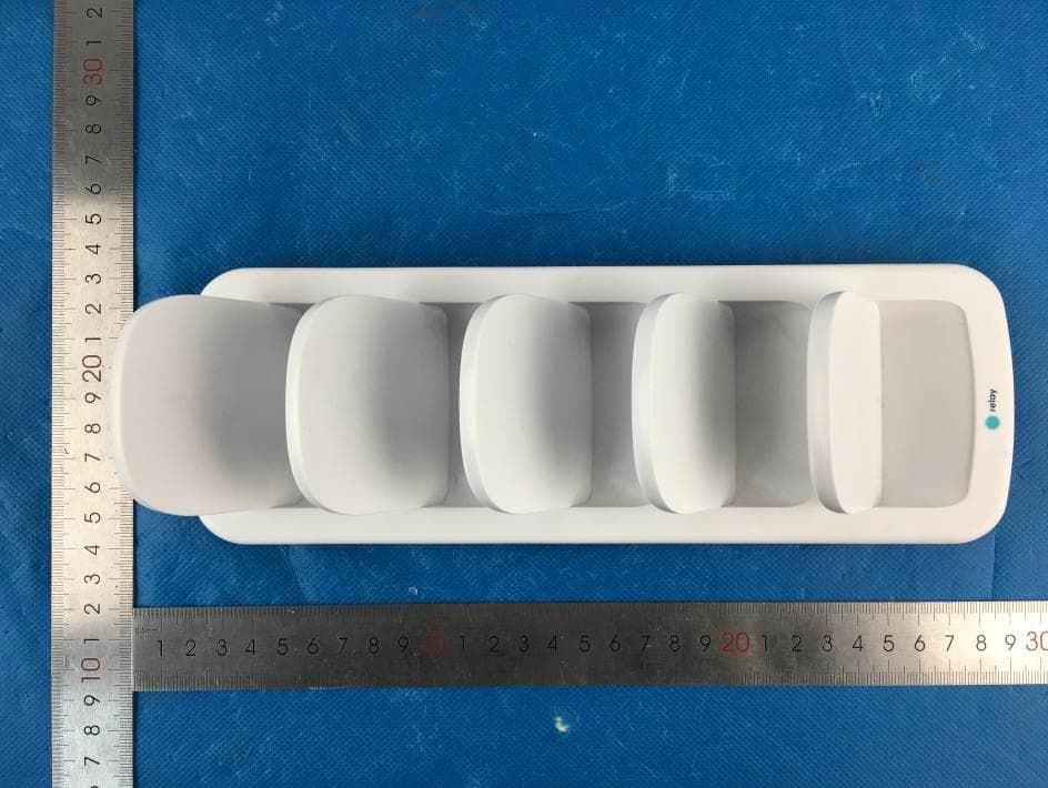
2AMBHRW1702
Jan 07, 2021Multi-unit Wireless Charger
Equipment Class
DCD - Part 15 Low Power Transmitter Below 1705 kHz
2AMBHRW2266
Mar 09, 2020Relay+
Equipment Class
JAB - Part 15 Class B Digital Device