2AML4-CAM1080Battery Camera Hub
Apollo Tech USA Inc.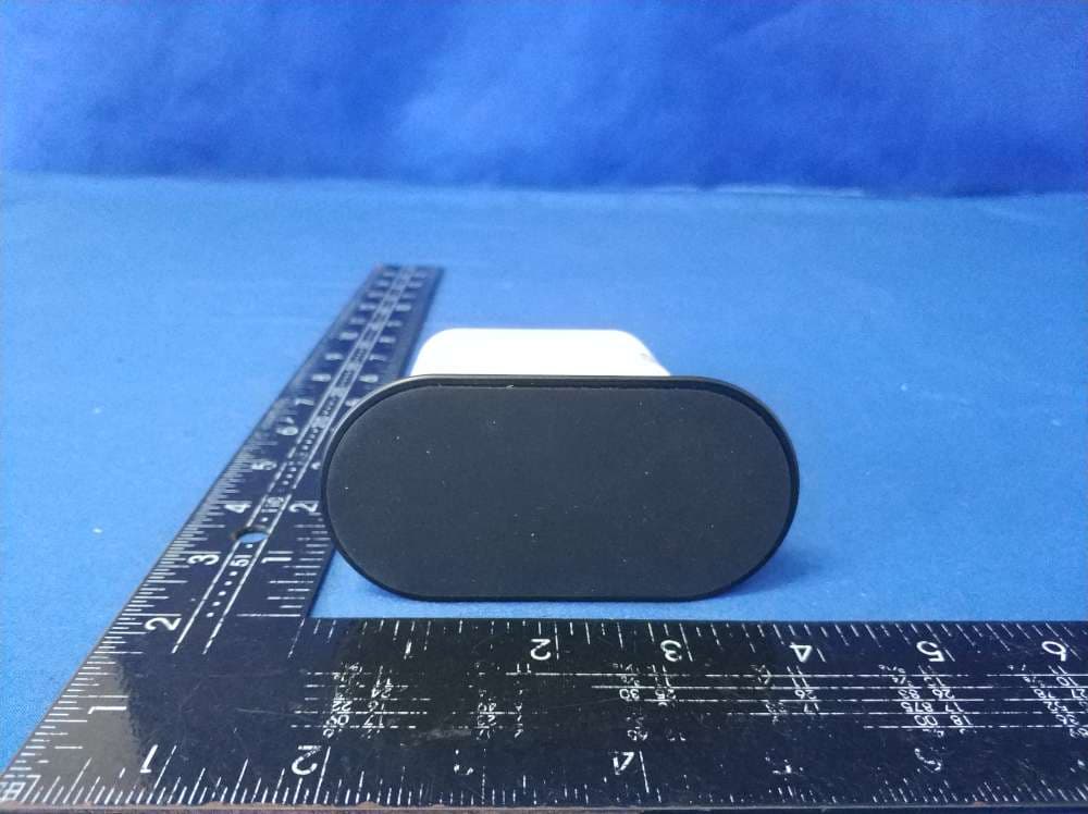
Click to zoom
Application Details
- Equipment Class
- DTS - Digital Transmission System
- Date of Grant
- Aug 20, 2020
- Application Purpose
- Original Equipment
- Date of Application
- Aug 20, 2020
- Equipment Note
- Battery Camera Hub
- Frequency Range
- 2402.00000000 - 2480.00000000
- Company
- Apollo Tech USA Inc.
- Country
- United States
Documents & Files
Document Text
Text extracted from the exhibit documents filed with the FCC. Open a document above to read the original.
Users Manual
INSTALLATION GUIDE Teri™ Wire-Free Outdoor Battery Camera Tori_Instruction2.indd 18/12/20 3:55 PM 2 TABLE OF CONTENTS Contents 1 WHAT’S IN THE BOX? 4 MOMENTUM SECURE APP 6 PAIRING 6 INSTRUCTIONS 9 CAMERA INSTALLATION 14 FEATURES 18 TROUBLESHOOTING 26 WARRANTY Tori_Instruction2.indd 28/12/20 3:55 PM 1 WHAT’S IN THE BOX Accessories Tori_Instruction2.indd 18/12/20 3:55 PM 2 WHAT’S INCLUDED Before you Begin For Smart Hub Installation Smart HubHub Power CordHub Power AdapterEthernet Cable Check to make sure you have all the pieces and accessories that should be included in the box. Tori_Instruction2.indd 28/12/20 3:55 PM 3 WHAT’S INCLUDED For Camera Installation Teri Camera (2) Charging Adapter Ball Mount (2) Charging Cable Screw Mount (2) Mounting Screw (6) Mounting Sticker (2) Wall Anchors (6) Tori_Instruction2.indd 38/12/20 3:55 PM 2 MOMENTUM SECURE APP Downloading the App Tori_Instruction2.indd 48/12/20 3:55 PM 5 MOMENTUM SECURE APP • Download the Momentum Secure App from the Apple App Store or Google Play Store. • Create a new account with your email address or login to your existing account. Tori_Instruction2.indd 58/12/20 3:55 PM 3 PAIRING INSTRUCTIONS Connecting the Smart Hub Pairing Tori_Instruction2.indd 68/12/20 3:55 PM 7 PAIRING INSTRUCTIONS 1. Connect the ethernet cable to the Smart Hub and WiFi router. 2. Power the Smart Hub by connecting the Hub power adapter to a nearby outlet. STEP 1 - Connect the Smart Hub 3. Wait for the indicator light to turn solid blue. Tori_Instruction2.indd 78/12/20 3:55 PM 8 PAIRING INSTRUCTIONS 1. Tap the + icon to add a new device. 2. Select the Teri camera option. STEP 2 - Pair the Smart Hub and Camera 3. Follow the on-screen app instruc- tions to complete the pairing process. Tori_Instruction2.indd 88/12/20 3:56 PM 4 CAMERA INSTALLATION Installation Height Mounting Tori_Instruction2.indd 98/12/20 3:56 PM 10 CAMERA INSTALLATION • It is recommended to install the camera between 7-10 ft off the ground for the best performance. • Avoid installing in places where the camera will be directly exposed to sunlight. • Make sure you pick a spot where the camera will still get good wireless signal strength. Camera Placement Tori_Instruction2.indd 108/12/20 3:56 PM 11 CAMERA INSTALLATION • You will find two types of mounting bases in the box. Choose one that you’re more comfortable with using. • Ball Mount: Magnetically attaches to the back of the camera. • Screw Mount: Screws into the back of the camera’s screw-hole. Ball MountScrew Mount Choosing your Mount Tori_Instruction2.indd 118/12/20 3:56 PM 12 CAMERA INSTALLATION 1. For hard surfaces like stone, brick, or stucco, drill a hole using a 9/64 inch (3.55mm) drill bit, then insert the wall anchor. * Note: if you have a softer surface like wood, you can skip this step. 2. Drill the screw into the surface or wall anchor. Make sure you leave a bit of the screw exposed. 3. Hang the ball mount onto the exposed screw. 4. Attach the camera to the ball mount. Make sure to adjust the camera angle as necessary. Ball Mount Installation 1 2 3 4 Tori_Instruction2.indd 128/12/20 3:56 PM 13 CAMERA INSTALLATION 1. For hard surfaces like stone, brick, or stucco, drill holes using a 9/64 inch (3.55mm) drill bit, then insert the 3 wall anchors. * Note: if you have a softer surface like wood, you can skip this step. 2. Place the screw mount over the marked holes on the surface, then drill the screws through the holes of the screw mount and into the surface or wall an- chors. 3. Screw the camera onto the screw mount and make sure it’s securely locked by twisting the silver knob. Screw Mount Installation 1 2 3 Tori_Instruction2.indd 138/12/20 3:56 PM 5 FEATURES Dashboard Key Features Tori_Instruction2.indd 148/12/20 3:56 PM 15 FEATURES Your dashboard is your app’s home screen where you can view your devices, menu, settings, history, and more. Dashboard MenuAdd Drevice Add Counter HomeHistorySetting Camera Preview Tori_Instruction2.indd 158/12/20 3:56 PM 16 FEATURES Create and customize up to 3 motion zones so you can focus on the most important areas of your home. When motion is detected, you’ll get an alert instantly to your mobile device. Have the camera only alert you based on human-shaped objects to help avoid false alerts due to shadows, lighting, plants, and others. Motion Zones Human Detection Tori_Instruction2.indd 168/12/20 3:56 PM 17 FEATURES The Teri camera will make sure you stay protected day and night. The built-in in- frared LEDs turn on automatically in low light condition and allows you see up to 32 feet in the dark. Every camera comes with FREE 24-hr video history that can be played back from the app. You can even download the recordings directly to your mobile device for permanent safe-keeping. Night Vision Free Cloud Storage Tori_Instruction2.indd 178/12/20 3:56 PM 6 TROUBLESHOOTING Indicator Light Common Issues FA Q s Tori_Instruction2.indd 188/12/20 3:56 PM 19 TROUBLESHOOTING Indicator Light LED Color Solid Red Blinking Red Blinking Red and Blue Solid Green Solid Blue LED Color Solid Red Blinking Red Blinking Red and Blue Solid Green Solid Blue Description Booting Offline Pairing Mode Camera Synced Live stream/recording in Progress Description Booting Offline Pairing Mode Synced with Camera Online Tori_Instruction2.indd 198/12/20 3:56 PM 20 TROUBLESHOOTING If your camera is having app or streaming connection issues, try these steps to correct the issue. Force close the app If you’re experience issues with the app, many times it can be resolved by restarting the app. Completely close the app on your mobile device then open the app again. Power cycle the Hub Unplug the hub, wait 10 seconds, then plug it back in. Reset the Smart Hub 1. To reset the hub, hold the Reset button on the back of the hub for about 10 seconds. During the reset sequence, the LED indicator light on the front of the hub will first dis- play solid red, then solid blue. 2. Once the hub is blinking red and blue, you will need to pair the ca…
Text truncated - open the document above for the full version.
External Photos
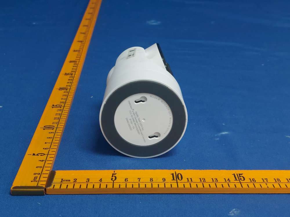
2AML4-CAM1080
Internal Photos
2AML4-CAM1080 WIFI Antenna BT Antenna
RF Exposure Info
1. M e t h o d o f m e a s u r e m e n t 1.1. Applicable Standard According to §1.1307(b)(1), systems operating under the provisions of this section shall be operated in a manner that ensures that the public is not exposed to radio frequency energy level in excess of the Commission’s guidelines. According to §1.1310 and §2.1091 RF exposure requirement KDB447498 v06: Mobile and Portable Devices RF Exposure Procedures and Equipment Authorization Policies. FCC ID:2AML4-CAM1080 1.2. Requirement According to KDB447498 D01 General RF Exposure Guidance v06 Section 4.3.1 Standalone SAR test exclusion considerations: “Unless specifically required by the published RF exposure KDB procedures, standalone 1-g head or body and 10-g extremity SAR evaluation for general population exposure conditions, by measurement or numerical simulation, is not required when the corresponding SAR Test Exclusion Threshold condition, listed below, is satisfied. These test exclusion conditions are based on source-based time-averaged maximum conducted output power of the RF channel requiring evaluation, adjusted for tune-up tolerance, and the minimum test separation distance required for the exposure conditions.22 The minimum test separation distance is determined by the smallest distance from the antenna and radiating structures or outer surface of the device, according to the host form factor, exposure conditions and platform requirements, to any part of the body or extremity of a user or bystander (see 5) of section 4.1). To qualify for SAR test exclusion, the test separation distances applied must be fully explained and justified by the operating configurations and exposure conditions of the transmitter and applicable host platform requirements, typically in the SAR measurement or SAR analysis report, according to the required published RF exposure KDB procedures. When no other RF exposure testing or reporting is required, a statement of justification and compliance must be included in the equipment approval, in lieu of the SAR report, to qualify for the SAR test exclusion. When required, the device specific conditions described in the other published RF exposure KDB procedures must be satisfied before applying these SAR test exclusion provisions; for example, handheld PTT two-way radios, handsets, laptops & tablets etc.23 “ [(max. power of channel, including tune-up tolerance, mW)/ (min. test separation distance, mm)] · [√f (GHz)] ≤ 3.0 for 1-g SAR and ≤ 7.5 for 10-g extremity SAR, where: • f (GHz) is the RF channel transmit frequency in GHz • Power and distance are rounded to the nearest mW and mm before calculation • The result is rounded to one decimal place for comparison • 3.0 and 7.5 are referred to as the numeric thresholds in the step 2 below The test exclusions are applicable only when the minimum test separation distance is ≤ 50 mm and for transmission frequencies between 100 MHz and 6 GHz. When the minimum test separation distance is < 5 mm, a distance of 5 mm according to 5) in section 4.1 is applied to determine SAR test exclusion. Report No.: UNIA20061216-1FR Page 2 of 3 1.3. Limit Limits for Maximum Permissible Exposure (MPE)/Controlled Exposure Frequency Range(MHz) Electric Field Strength(V/m) Magnetic Field Strength(A/m) Power Density (mW/cm²) Averaging Time (minute) Limits for Occupational/Controlled Exposure 0.3 – 3.0 3.0 – 30 30 – 300 300 – 1500 1500 – 100,000 614 1842/f 61.4 / / 1.63 4.89/f 0.163 / / (100) * (900/f 2 )* 1.0 f/300 5 6 6 6 6 6 Limits for Maximum Permissible Exposure (MPE)/Uncontrolled Exposure Frequency Range(MHz) Electric Field Strength(V/m) Magnetic Field Strength(A/m) Power Density (mW/cm²) Averaging Time (minute) Limits for Occupational/Controlled Exposure 0.3 – 3.0 3.0 – 30 30 – 300 300 – 1500 1500 – 100,000 614 824/f 27.5 / / 1.63 2.19/f 0.073 / / (100) * (180/f 2 )* 0.2 f/1500 1.0 30 30 30 30 30 F=frequency in MHz *=Plane-wave equivalent power density 1.4. MPE Calculation Method Predication of MPE limit at a given distance Equation from page 18 of OET Bulletin 65, Edition 97-01 S=PG/4πR² Where: S=power density P=power input to antenna G=power gain of the antenna in the direction of interest relative to an isotropic radiator R=distance to the center of radiation of the antenna As declared by the Applicant, the EUT transmits with the maximum soure-baed Duty Cycle of 100%-see the User manual, and the EUT is a wireless device used in a mobile application, at least 20 cm from any body part of the user or nearby persons; from the maximum EUT RF output power, the minimum mobile separation distance, r =20cm, as well as the gain of the used antenna is 3.5dBi for WLAN and BT Antenna is 2.5dBi, and the power drift from Turn-up Procedure provide by manufacturer as following states, the RF power density can be obtained.. Report No.: UNIA20061216-1FR Page 3 of 3 1.5. Antenna Information only use antennas certificated as follows provided by manufacturer; Antenna Identification in Internal photos Antenna type and antenna number Operate frequency band Maximum antenna gain 2.4G Wifi Internal Antenna 2.412GHz – 2.462 GHz 3.5dBi BLE Internal Antenna 2.402GHz – 2.480 GHz 2.5dBi Evaluation Results for Standalone WIFI Modulati on Type Target power W/ tolerance (dBm) Max tune up power tolerance(dB m) Max Output power to antenna (mW) Antenna Gain (Numeric) Power Density at R=20cm (mW/cm2) Limit (mW/cm2) Result 802.11b 12±1.0 13 19.953 3.5 0.00889 1.0 Pass 802.11g 12±1.0 13 19.953 3.5 0.00889 1.0 Pass 802.11n (HT20) 11±1.0 12 15.849 3.5 0.00706 1.0 Pass 802.11n (HT40) 10±1.0 11 12.589 3.5 0.00561 1.0 Pass BLE Freq. (MHz) Output Power (dBm) Target power W/ tolerance (dBm) Max tune up power tolerance (dBm) Output power to antenna (mW) Ant Gain (dBi) Power Density at R=20cm (mW/cm2) Limit (mW/c m2) Result GFSK 2402 4.359 4±1.0 5 3.162 2.5 0.00112 1 Pass 2440 3.784 3±1.0 4 2.512 2.5 0.00089 1 Pass 2480 3.426 3±1.0 4 2.512 2.5 0.00089 1 Pass Simultaneously MPE MPE Ratio BLE (mW/cm 2 ) MPE Ratio 2.4GWLAN …
Text truncated - open the document above for the full version.
Test Report
Page1of54ReportNo.:UNIA20061216FR-01 FCCRADIOTESTREPORT FCCID:2AML4-CAM1080 Product : BatteryCameraHub TradeName : Momentum ModelName: MOCAMOUT1080-01 SerialModel: N/A ReportNo. : UNIA20061216FR-01 Preparedfor ApolloTechUSAInc. TechUSAInc.8608UticaAve#220,RanchoCucamonga,California, UnitedStates Preparedby ShenzhenUnitedTestingTechnologyCo.,Ltd. 2F,AnnexBldg,JiahuangyuanTechPark,#365Baotian1Rd,Tiegang Community,XixiangStr,Bao'anDistrict,Shenzhen,China Page2of54ReportNo.:UNIA20061216FR-01 TESTRESULTCERTIFICATION Applicant’sname....................: ApolloTechUSAInc. Address......................................: TechUSAInc.8608UticaAve#220,RanchoCucamonga, California,UnitedStates Manufacture'sName..............: ApolloTechUSAInc. Address......................................: TechUSAInc.8608UticaAve#220,RanchoCucamonga, California,UnitedStates Productdescription Productname............................... : BatteryCameraHub TradeMark.................................: Momentum Modeland/ortypereference . : MOCAMOUT1080-01 Standards..................................: FCCRulesandRegulationsPart15SubpartCSection15.247 ANSIC63.10:2013 ThisdevicedescribedabovehasbeentestedbyShenzhenUnitedTestingTechnology Co.,Ltd.,andthetestresultsshowthattheequipmentundertest(EUT)isincompliance withtheFCCrequirements.Anditisapplicableonlytothetestedsampleidentifiedinthe report. Thisreportshallnotbereproducedexceptinfull,withoutthewrittenapprovalofUNI,this documentmaybealteredorrevisedbyShenzhenUnitedTestingTechnologyCo.,Ltd., personnelonly,andshallbenotedintherevisionofthedocument. DateofTest...............................................: Date(s)ofperformanceoftests...............: Jun.06~18,2020 DateofIssue..............................................: Jun.19,2020 TestResult .................................................. :Pass Testby: Bobliao/Enginner Reviewer: Kahnyang/Supervisor Approved&AuthorizedSigner: Liuze/Manager Page3of54ReportNo.:UNIA20061216FR-01 TableofContentsPage 1.TESTSUMMARY...................................................................................................................5 2.GENERALINFORMATION...................................................................................................6 2.1GENERALDESCRIPTIONOFEUT.........................................................................................6 2.2CarrierFrequencyofChannels.................................................................................................7 2.3OperationofEUTduringtesting................................................................................................7 2.4DESCRIPTIONOFTESTSETUP.............................................................................................7 2.5MEASUREMENTINSTRUMENTSLIST..................................................................................8 3.CONDUCTEDEMISSIONSTEST .................................................................................... 9 3.1ConductedPowerLineEmissionLimit.....................................................................................9 3.2TestSetup.....................................................................................................................................9 3.3TestProcedure.............................................................................................................................9 3.4TestResult....................................................................................................................................9 4.RADIATEDEMISSIONTEST.............................................................................................12 4.1RadiationLimit ........................................................................................................................... 12 4.2TestSetup ................................................................................................................................... 12 4.3TestProcedure ........................................................................................................................... 13 4.4TestResult .................................................................................................................................. 13 5.BANDEDGE.........................................................................................................................28 5.1Limits...........................................................................................................................................28 5.2TestProcedure...........................................................................................................................28 5.3TestResult..................................................................................................................................28 6.OCCUPIEDBANDWIDTHMEASUREMENT .................................................................. 31 6.1TestLimit.....................................................................................................................................31 6.2TestProcedure...........................................................................................................................31 6.3MeasurementEquipmentUsed...............................................................................................31 6.4TestResult..................................................................................................................................31 7.POWERSPECTRALDENSITYTEST..............................................................................38 7.1TestLimit ..................................................................................................................................... 38 7.2TestProcedure ........................................................................................................................... 38 7.3MeasurementEquipmentUsed ............................................................................................... 38 7.4TestResult…
Text truncated - open the document above for the full version.
Test Report
Page49of54ReportNo.:UNIA20061216FR-01 10.SPURIOUSRFCONDUCTEDEMISSION 10.1TestLimit 1.Below-20dBofthehighestemissionlevelinoperatingband. 2.Fallintherestrictedbandslistedinsection15.205.Themaximumpermittedaveragefieldstrengthis listedinsection15.209. 3.Forbelow30MHz,For9KHz-150kHz,150K-10MHz,WeusetheRBW1KHz,10KHz,Sothelimitneedto calculatedby“10lg(BW1/BW2)“.forexampleFor9KHz-150kHz,RBW1KHz,TheLimit=thehighest emissionlevel-20-10log(100/1)=thehighestemissionlevel-40. 10.2TestProcedure TheSpuriousRFconductedemissionscomplianceofRFradiatedemissionshouldbemeasuredby followingtheguidanceinANSIC63.10-2013,For9KHz-150kHz,SetRBW=1kHzandVBW=3KHz; For150KHz-10MHz,SetRBW=10kHzandVBW=30KHz:For10MHz-25GHz,SetRBW=100kHzand VBW=300KHzinordertomeasurethepeakfieldstrength,andmwasurefrequenyrangefrom9KHz to25GHz. 10.3TestSetup 10.4TestResult PASS Remark:Themeasurementfrequencyrangeisfrom9KHztothe10thharmonicofthe fundamentalfrequency.Thelowest,middleandhighestchannelsaretestedtoverifythe spuriousemissionsandbandegemeasurementdata. andrecordtheworstestdatafor802.11bin report. Page50of54ReportNo.:UNIA20061216FR-01 TestMode:802.11bTestchannel:01 Channel01 30MHz~3GHz 3GHz~25GHz Page51of54ReportNo.:UNIA20061216FR-01 TestMode:802.11bTestchannel:06 Channel06 30MHz~3GHz 3GHz~25GHz Page52of54ReportNo.:UNIA20061216FR-01 TestMode:802.11bTestchannel:11 Channel11 30MHz~3GHz 3GHz~25GHz Page53of54ReportNo.:UNIA20061216FR-01 11.ANTENNAREQUIREMENT StandardApplicable: Forintentionaldevice,accordingtoFCC47CFRSection15.203,anintentionalradiatorshallbe designedtoensurethatnoantennaotherthanthatfurnishedbytheresponsiblepartyshallbe usedwiththedevice. AntennaConnectedConstruction TheantennausedinthisproductisanInternalAntenna,Thedirectionalgainsofantennausedfor transmittingis3.5dBi. ANTENNA: Page54of54ReportNo.:UNIA20061216FR-01 12.PHOTOGRAPHOFTEST RadiatedEmission (Below1G) RadiatedEmission (Above1G) ConductedEmission ***EndofReport***
Test Report
Page1of35ReportNo.:UNIA20061216FR-02 FCCRADIOTESTREPORT FCCID:2AML4-CAM1080 Product :BatteryCameraHub TradeName :Momentum ModelName:MOCAMOUT1080-01 SerialModel:N/A ReportNo. :UNIA20061216FR-02 Preparedfor ApolloTechUSAInc. TechUSAInc.8608UticaAve#220,RanchoCucamonga,California, UnitedStates Preparedby ShenzhenUnitedTestingTechnologyCo.,Ltd. 2F,AnnexBldg,JiahuangyuanTechPark,#365Baotian1Rd,Tiegang Community,XixiangStr,Bao'anDistrict,Shenzhen,China Page2of35ReportNo.:UNIA20061216FR-02 TESTRESULTCERTIFICATION Applicant’sname .................... : ApolloTechUSAInc. Address ...................................... : TechUSAInc.8608UticaAve#220,RanchoCucamonga, California,UnitedStates Manufacture'sName..............: ApolloTechUSAInc. Address ...................................... : TechUSAInc.8608UticaAve#220,RanchoCucamonga, California,UnitedStates Productdescription Productname...............................: BatteryCameraHub TradeMark.................................: Momentum Modeland/ortypereference.: MOCAMOUT1080-01 Standards .................................. : FCCRulesandRegulationsPart15SubpartCSection15.247, ANSIC63.10:2013 ThisdevicedescribedabovehasbeentestedbyShenzhenUnitedTestingTechnology Co.,Ltd.,andthetestresultsshowthattheequipmentundertest(EUT)isincompliance withtheFCCrequirements.Anditisapplicableonlytothetestedsampleidentifiedinthe report. Thisreportshallnotbereproducedexceptinfull,withoutthewrittenapprovalofUNI,this documentmaybealteredorrevisedbyShenzhenUnitedTestingTechnologyCo.,Ltd., personnelonly,andshallbenotedintherevisionofthedocument. DateofTest ............................................... : Date(s)ofperformanceoftests ............... : Jun.06~18,2020 DateofIssue..............................................: Jun.19,2020 TestResult .................................................. :Pass Testby: Bobliao/Enginner Reviewer: Kahnyang/Supervisor Approved&AuthorizedSigner: Liuze/Manager Page3of35ReportNo.:UNIA20061216FR-02 TableofContentsPage 1.TESTSUMMARY...................................................................................................................5 1.1TESTPROCEDURESANDRESULTS .................................................................................. 5 1.2TESTFACILITY .......................................................................................................................... 5 1.3MEASUREMENTUNCERTAINTY .......................................................................................... 5 2.GENERALINFORMATION...................................................................................................6 2.1GENERALDESCRIPTIONOFEUT.......................................................................................6 2.2CarrierFrequencyofChannels...............................................................................................7 2.3OperationofEUTduringtesting..............................................................................................7 2.4DESCRIPTIONOFTESTSETUP...........................................................................................7 2.5MEASUREMENTINSTRUMENTSLIST................................................................................8 3.CONDUCTEDEMISSIONSTEST ....................................................................................... 9 3.1ConductedPowerLineEmissionLimit.....................................................................................9 3.2TestSetup.....................................................................................................................................9 3.3TestProcedure.............................................................................................................................9 3.4TestResult....................................................................................................................................9 4.RADIATEDEMISSIONTEST.............................................................................................10 4.1RadiationLimit ........................................................................................................................... 12 4.2TestSetup ................................................................................................................................... 12 4.3TestProcedure ........................................................................................................................... 13 4.4TestResult .................................................................................................................................. 13 5.BANDEDGE.........................................................................................................................19 5.1Limits...........................................................................................................................................19 5.2TestProcedure...........................................................................................................................19 5.3TestResult..................................................................................................................................19 6.OCCUPIEDBANDWIDTHMEASUREMENT .................................................................. 21 6.1TestLimit.....................................................................................................................................21 6.2TestProcedure...........................................................................................................................21 6.3MeasurementEquipmentUsed...............................................................................................21 6.4TestResult..................................................................................................................................21 7.POWERSPECTRALDENSITYTEST..............................................................................23 7.1TestLimit ..................................................…
Text truncated - open the document above for the full version.
Test Setup Photos
2AML4-CAM1080 Radiated Emission (Below 1G) Radiated Emission (Above 1G) Conducted Emission
Contact Information
Applicant
Albert Ling
Test Firm
Shenzhen United Testing Technology Co., Ltd.Liu Ze
[email protected]86-755-86180996
Technical Specifications
| # | Rule Parts | Frequency Range | Power Output |
|---|---|---|---|
| 2 | 15C | 2.40 GHz - 2.48 GHz | 2.70 mW |
Other Applications from Apollo Tech USA Inc.
2AML4MOGA2K001
Sep 24, 2022Niro2 WiFi Garage Controller and Camera
Equipment Class
DTS - Digital Transmission System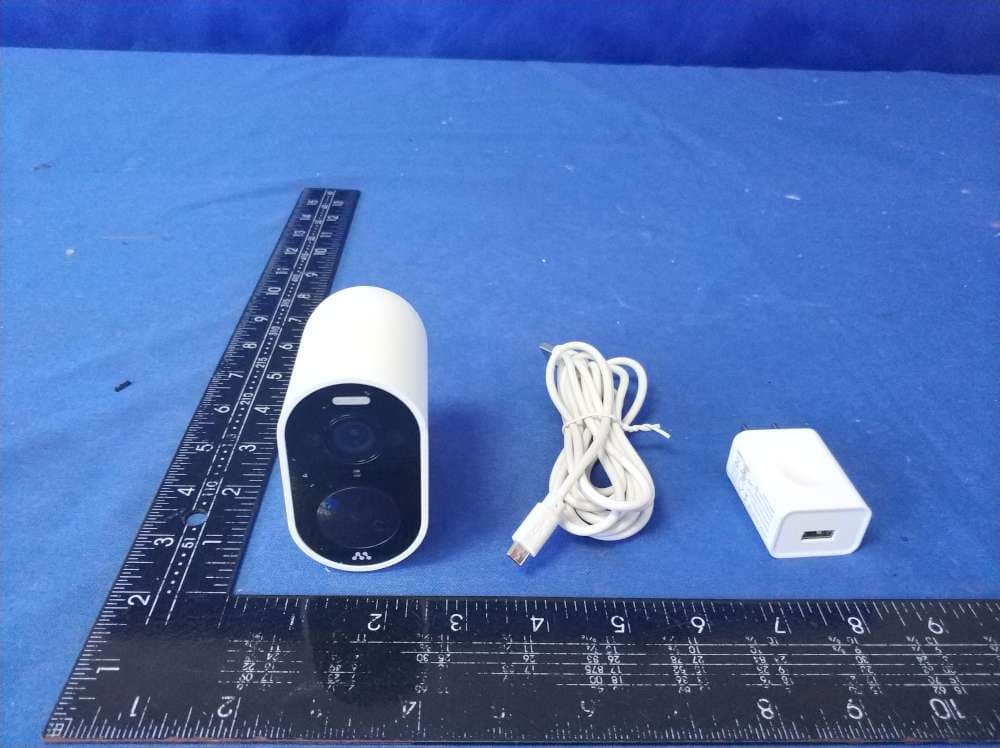
2AML4-MOCAMOUT
Aug 20, 20201080P HD WiFi Battery Camera
Equipment Class
DTS - Digital Transmission System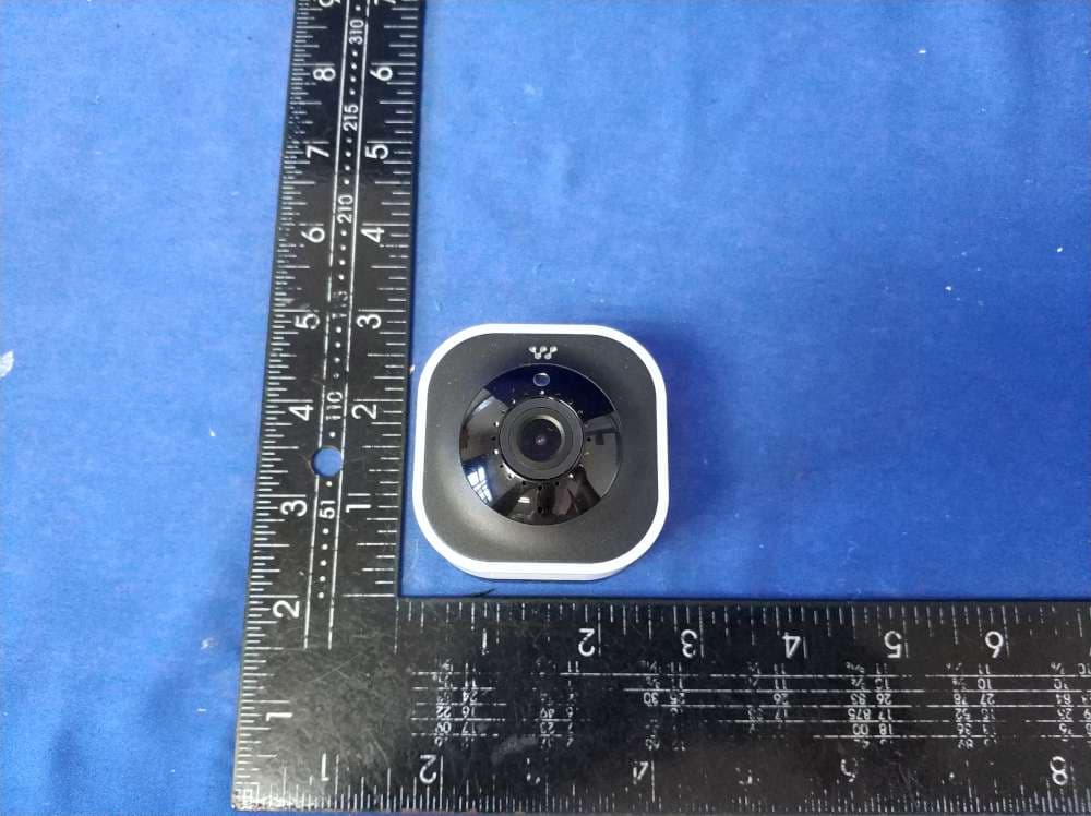
2AML4-CAMIND2K
Jun 07, 20202K HD WiFi Camera
Equipment Class
DTS - Digital Transmission System