2AML4-CAMIND2K2K HD WiFi Camera
Apollo Tech USA Inc.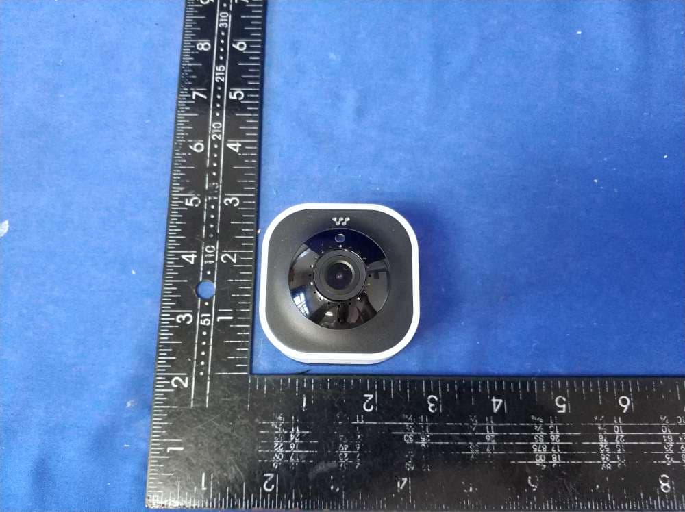
Click to zoom
Application Details
- Equipment Class
- DTS - Digital Transmission System
- Date of Grant
- Jun 07, 2020
- Application Purpose
- Original Equipment
- Date of Application
- Jun 07, 2020
- Equipment Note
- 2K HD WiFi Camera
- Frequency Range
- 2402.00000000 - 2480.00000000
- Company
- Apollo Tech USA Inc.
- Country
- United States
Documents & Files
Document Text
Text extracted from the exhibit documents filed with the FCC. Open a document above to read the original.
Users Manual
1 Codi ™ 2K WiFi Video Camera QUICK START GUIDE Features What’s in the box Momentum Secure App Pairing Instructions Troubleshooting Device Information Frequently Asked Questions 4 5 6 7 9 14 16 TABLE OF CONTENTS 4 WHAT’S IN THE BOX Metal Mounting Plate Power Adapter Codi CameraPower Cable Double-Sided Sticker Screws (x2) Wall Anchors (x2) 5 DEVICE INFORMATION Microphone Light Sensor Speaker Camera Lens LED Indicator Micro SD Card Slot Reset Button Power Port 6 MOMENTUM SECURE APP Download the Momentum Secure app on your mobile device in order to use the camera. Make sure the logo you download matches the one shown below. Creating an Account If you don’t already have a Momentum Secure account, you will need to create one. You can follow the in-app instructions to sign up for a new account. Note that you will need to have access to your email to complete the process. 7 PAIRING INSTRUCTIONS Step 1 - Power the Camera • Connect the power adapter and power cable to the camera’s power port. • Plug the power adapter into a wall socket. • You should now see the LED indicator in the front of the camera light up. • Wait for the camera to say “The camera is ready to be paired.” 8 PAIRING INSTRUCTIONS • Tap the + icon to add a new device. • Select the Codi camera option. • Follow the on-screen app instructions to complete the pairing process. Step 2 - Connect to the Camera 9 FEATURES Step 3 - Test it Out! • After the pairing is complete, tap on the camera tile on the dashboard to see the live stream. • Customize the camera’s settings to your preferences from the Settings page. 10 FEATURES Dashboard Add Device Activity Counter Settings Menu Camera Preview Home Activity History 11 FEATURES Motion Zones Create and customize up to 3 motion zones so you can focus on the most important areas of your home. When motion is detected, you’ll get an alert instantly to your mobile device. 12 FEATURES Human Detection Have the camera only alert you based on human-shaped objects to help avoid false alerts due to shadows, lighting, plants, and others. 13 FEATURES Night Vision The Codi camera will make sure you stay protected day and night. The built-in infrared LEDs turn on automatically in low light and allows you see up to 30 feet in the dark. Free Cloud storage Every camera comes with FREE 24-hr video history that can be played back from the app. You can even download the recordings directly to your mobile device for permanent safe-keeping. 14 TROUBLESHOOTING The camera’s LED indicator light will let you know what it’s doing. Solid RedCamera is booting Disconnected from WiFi Camera is in pairing mode Live stream/recording in progress Blinking Red Blinking Red and Blue Solid Blue z LED ColorDescription 15 TROUBLESHOOTING If your camera is having app, streaming, or connection issues, try these steps to correct the issue. Force close the app If you’re experience issues with the app, many times it can be resolved by restarting the app. Completely close the app on your mobile device then open the app again. Power cycle the camera Unplug the camera, wait 10 seconds, then plug it back in. Reset the camera 1. To reset the camera, hold the Reset button on the back of the camera for about 10 seconds. During the reset sequence, the LED indicator display solid red, then blinking blue. 2. Once the camera is blinking red and blue, you will need to pair the camera again. 16 FAQs • Make sure your Bluetooth and location settings are turned on from your mobile device. Also make sure the camera is in pairing mode. • Make sure that you’ve downloaded the correct Momentum Secure app from the app store. Do I need a microSD card to record videos? • A microSD card is not necessary as every camera comes with free cloud storage that allows you to save recorded activity for 24 hours. Why can’t the camera read the microSD card? • The camera can only support up to 128GB cards and must be in FAT32 format. You can also try formatting the SD card from the camera’s General settings page. Why does my camera keep disconnecting? • The camera may have a poor internet connection with your router. Try moving the camera closer to your router and make sure the network is stable. • You can also try the ‘WiFi Network Test’ from the camera’s settings page to test your network speed. 17 FAQs Why does the stream keep failing to load? • There could be several reasons, but most commonly it may be due to poor internet connection from the mobile device you’re using to stream the camera. Make sure you have a strong internet connection while attempting to stream. Why is the video stream so slow? • This may be caused by a slow internet connection from the camera. You can try improving the video speed by lowering the video resolution from the camera settings. Do I need a microSD card to record videos? • This may be caused by a slow internet connection from the camera. You can try improving the video speed by lowering the video resolution from the camera settings. Why is there a big glare when I have the camera facing my window? • glass. You can mitigate this by turning off the night vision setting, however you will lose the ability to see in dark environments. How do I recover recordings that have expired from the cloud? • Cloud recordings that have already expired cannot be recovered. It is recommended to download the recordings directly to your mobile device before they expire. For further assistance, please see our help page at https://support.momentumcam.com. Disclaimers • Mobile device OS compatibility is subject to change as new versions are released. It is recommended to stay up-to-date with the latest OS versions to ensure the app will stay compatible. • App screens and functions may change overtime as we continue to improve our software. Please refer to our website for the latest guides available. FCC Statement This equipment has been tested and found to comply with the limits for a ClassB digital device, pursuant to part 15 of the FCC rules. These limits are…
Text truncated - open the document above for the full version.
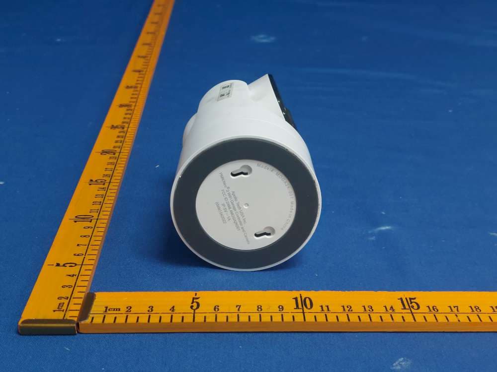
External Photos
FCC ID:2AML4-CAMIND2K
RF Exposure Info
1. Method of measurement 1.1. Applicable Standard According to §1.1307(b)(1), systems operating underthe provisions of this section shall be operated in a manner that ensures that the public is not exposed to radio frequency energy level in excess of the Commission’s guidelines. According to §1.1310 and §2.1091 RF exposure requirement KDB447498 v06: Mobile and Portable Devices RF Exposure Procedures and Equipment Authorization Policies. FCC ID:2AML4-CAMIND2K 1.2. Requirement According to KDB447498 D01 General RF Exposure Guidance v06 Section 4.3.1 Standalone SAR test exclusion considerations: “Unless specifically required by the published RF exposure KDB procedures, standalone 1-g head or body and 10-g extremity SAR evaluation for general population exposure conditions, by measurement or numerical simulation, is not required when the corresponding SAR Test Exclusion Threshold condition, listed below, is satisfied. These test exclusion conditions are based on source-based time-averaged maximum conducted output power of the RF channel requiring evaluation, adjusted for tune-up tolerance, and the minimum test separation distance required for the exposure conditions.22 The minimum test separation distance is determined by the smallestdistance from the antenna and radiating structures or outer surface of the device, according to the host form factor, exposure conditions and platform requirements, to any part of the body or extremity of a user or bystander (see 5) of section 4.1). To qualify for SAR test exclusion, the test separation distances applied must be fully explained and justified by the operating configurations and exposure conditions of the transmitter and applicable host platform requirements, typically in the SAR measurement or SAR analysis report, according to the required published RF exposure KDB procedures. When no other RF exposure testing or reporting is required, a statement of justification and compliance must be included in the equipment approval, in lieu of the SAR report, to qualify for the SAR test exclusion. When required, the device specific conditions described in the other published RF exposure KDB procedures must be satisfied before applying these SAR test exclusion provisions; for example, handheld PTT two-way radios, handsets, laptops & tablets etc.23 “ [(max. power of channel, including tune-up tolerance, mW)/ (min. test separation distance, mm)] · [√f(GHz)] ≤ 3.0 for 1-g SAR and ≤ 7.5 for 10-g extremity SAR, where: • f (GHz) is the RF channel transmit frequency in GHz • Power and distance are rounded to the nearest mW and mm before calculation • The result is rounded to one decimal place for comparison • 3.0 and 7.5 are referred to as the numeric thresholds in the step 2 below The test exclusions are applicable only when the minimum test separation distance is ≤ 50 mm and for transmission frequencies between 100 MHz and 6 GHz. When the minimum test separation distance is < 5 mm,adistanceof5mmaccordingto5)insection4.1isappliedtodetermineSARtestexclusion. Report No.: UNIA20042213-1FRPage 2 of 3 1.3. Limit Limits for Maximum Permissible Exposure (MPE)/Controlled Exposure Frequency Range(MHz) Electric Field Strength(V/m) Magnetic Field Strength(A/m) Power Density (mW/cm²) Averaging Time (minute) Limits fo rOccupational/Controlled Exposure 0.3–3.0 3.0–30 30 – 300 300 – 1500 1500 – 100,000 614 1842/f 61.4 / / 1.63 4.89/f 0.163 / / (100) * (900/f 2 )* 1.0 f/300 5 6 6 6 6 6 Limits for Maximum Permissible Exposure (MPE)/Uncontrolled Exposure Frequency Range(MHz) Electric Field Strength(V/m) Magnetic Field Strength(A/m) Power Density (mW/cm²) Averaging Time (minute) Limits fo rOccupational/Controlled Exposure 0.3–3.0 3.0–30 30 – 300 300 – 1500 1500 – 100,000 614 824/f 27.5 / / 1.63 2.19/f 0.073 / / (100) * (180/f 2 )* 0.2 f/1500 1.0 30 30 30 30 30 F=frequency in MHz *=Plane-wave equivalent power density 1.4. MPE Calculation Method Predication of MPE limit at a given distance Equation from page 18 of OET Bulletin 65, Edition 97-01 S=PG/4πR² Where: S=power density P=power input to antenna G=power gain of the antenna in the direction of interest relative to an isotropic radiator R=distance to the center of radiation of the antenna As declared by the Applicant, the EUT transmits with the maximum soure-baed Duty Cycle of 100%-see the User manual, and the EUT is a wireless device used in a mobile application, at least 20 cm from any body part of the user or nearby persons; from the maximum EUT RF output power, the minimum mobile separation distance, r =20cm, as well as the gain of the used antenna is 1.06dBi for WLAN, and the power drift from Turn-up Procedure provide by manufacturer as following states, the RF power density can be obtained.. Report No.: UNIA20042213-1FRPage 3 of 3 1.5. Antenna Information only use antennas certificated as follows provided by manufacturer ; Antenna Identification in Internal photos Antenna type and antenna number Operate frequency band Maximum antenna gain 2.4G Wifi +BLEInternal Antenna 2.412GHz – 2.462 GHz 2.402GHz- 2.480GHz 2.08 dBi Evaluation Results for Standalone WIFI Modulati on Type Target power W/ tolerance (dBm) Max tune up power tolerance(dB m) Max Output power to antenna (mW) Antenna Gain (Numeric) Power Density at R=20cm (mW/cm2) Limit (mW/cm2) Result 802.11b10±1.01112.5892.080.004041.0Pass 802.11g9±1.01010.0002.080.003211.0Pass 802.11n (HT20) 9±1.01010.0002.080.003211.0Pass 802.11n (HT40) 8±1.097.9432.080.002551.0Pass BLE Freq. (MHz) Output Power (dBm) Target power W/ tolerance (dBm) Max tune up power tolerance (dBm) Output power to antenna (mW) Ant Gain (dBi) Power Density at R=20cm (mW/cm2) Limit (mW/c m2) Result GFSK 2402 3.462 3±1.042.5122.08 0.000811Pass 2440 2.986 2±1.03 1.9952.08 0.00064 1Pass 2480 2.886 2±1.03 1.9952.08 0.00064 1Pass 2. Conclusion The measurement results comply with the FCC Limit per 47 CFR 2.1091 for the uncontrolled RF Exposure of mobile device. .....................End of Report........................…
Text truncated - open the document above for the full version.
Test Report
Page 1 of 54 Report No.: UNIA20042213FR-01 FCC RADIO TEST REPORT FCC ID: 2AML4-CAMIND2K Product: 2K HD WiFi Camera Trade Name: N/A Model Name: MOCAMIND2K-01 Serial Model: N/A Report No.: UNIA20042213FR-01 Prepared for Apollo Tech USA Inc. Tech USA Inc. 8608 Utica Ave #220, Rancho Cucamonga, California, United States Prepared by Shenzhen United Testing Technology Co., Ltd. 2F, Annex Bldg, Jiahuangyuan Tech Park, #365 Baotian 1 Rd, Tiegang Community, Xixiang Str, Bao'an District, Shenzhen, China Page 2 of 54 Report No.: UNIA20042213FR-01 TEST RESULT CERTIFICATION Applicant’s name .................... : Apollo Tech USA Inc. Address ...................................... : Tech USA Inc. 8608 Utica Ave #220, Rancho Cucamonga, California, United States Manufacture's Name .............. : Apollo Tech USA Inc. Address ...................................... : Tech USA Inc. 8608 Utica Ave #220, Rancho Cucamonga, California, United States Product description Product name ...............................: 2K HD WiFi Camera Trade Mark ................................. : N/A Model and/or type reference . : MOCAMIND2K-01 Standards .................................. : FCC Rules and Regulations Part 15 Subpart C Section 15.247 ANSI C63.10: 2013 This device described above has been tested by Shenzhen United Testing Technology Co., Ltd., and the test results show that the equipment under test (EUT) is in compliance with the FCC requirements. And it is applicableonly to the tested sample identified in the report. This report shall not be reproduced except infull, without the written approval of UNI, this document may be altered or revised by Shenzhen United Testing Technology Co., Ltd., personnel only, and shall be noted in the revision of the document. Date of Test ............................................... : Date (s) of performance of tests ............... : Apr. 10 ~ 22, 2020 Date of Issue .............................................. : Apr. 23, 2020 Test Result .................................................. :Pass Tested by: Kahn yang/Engineer Reviewer: Sherwin Qian/Supervisor Approved & Authorized Signer: Liuze/Manager Page 3 of 54 Report No.: UNIA20042213FR-01 Table of ContentsPage 1. TEST SUMMARY ................................................................................................................... 5 2. GENERAL INFORMATION ................................................................................................... 6 2.1 GENERAL DESCRIPTION OF EUT ......................................................................................... 6 2.2 Carrier Frequency of Channels ................................................................................................. 7 2.3 Operation of EUT during testing ................................................................................................ 7 2.4 DESCRIPTION OF TEST SETUP ............................................................................................. 7 2.5 MEASUREMENT INSTRUMENTS LIST .................................................................................. 8 3. CONDUCTED EMISSIONS TEST .................................................................................... 9 3.1 Conducted Power Line Emission Limit ..................................................................................... 9 3.2 Test Setup ..................................................................................................................................... 9 3.3 Test Procedure ............................................................................................................................. 9 3.4 Test Result .................................................................................................................................... 9 4. RADIATED EMISSION TEST ............................................................................................. 12 4.1 Radiation Limit ........................................................................................................................... 12 4.2 Test Setup ................................................................................................................................... 12 4.3 Test Procedure ........................................................................................................................... 13 4.4 Test Result .................................................................................................................................. 13 5. BAND EDGE ......................................................................................................................... 28 5.1 Limits ........................................................................................................................................... 28 5.2 Test Procedure ........................................................................................................................... 28 5.3 Test Result .................................................................................................................................. 28 6. OCCUPIED BANDWIDTH MEASUREMENT .................................................................. 31 6.1 Test Limit ..................................................................................................................................... 31 6.2 Test Procedure ........................................................................................................................... 31 6.3 Measurement Equipment Used ............................................................................................... 31 6.4 Test Result .................................................................................................................................. 31 7. POWER SPECTRAL DENSITY TEST .............................................................................. 38 7.1 Test Limit ....................................................................................…
Text truncated - open the document above for the full version.
Test Report
Page 1 of 35 Report No.: UNIA20042213FR-02 FCC RADIO TEST REPORT FCC ID: 2AML4-CAMIND2K Product: 2K HD WiFi Camera Trade Name: N/A Model Name: MOCAMIND2K-01 Serial Model: N/A Report No.: UNIA20042213FR-02 Prepared for Apollo Tech USA Inc. Tech USA Inc. 8608 Utica Ave #220, Rancho Cucamonga, California, United States Prepared by Shenzhen United Testing Technology Co., Ltd. 2F, Annex Bldg, Jiahuangyuan Tech Park, #365 Baotian 1 Rd, Tiegang Community, Xixiang Str, Bao'an District, Shenzhen, China Page 2 of 35 Report No.: UNIA20042213FR-02 TEST RESULT CERTIFICATION Applicant’s name....................: Apollo Tech USA Inc. Address ...................................... : Tech USA Inc. 8608 Utica Ave #220, Rancho Cucamonga, California, United States Manufacture's Name .............. : Apollo Tech USA Inc. Address ...................................... : Tech USA Inc. 8608 Utica Ave #220, Rancho Cucamonga, California, United States Product description Product name ............................... : 2K HD WiFi Camera Trade Mark ................................. : N/A Model and/or type reference . : MOCAMIND2K-01 Standards .................................. : FCC Rules and Regulations Part 15 Subpart C Section 15.247, ANSI C63.10: 2013 This device described above has been tested by Shenzhen United Testing Technology Co., Ltd., and the test results show that the equipment under test (EUT) is in compliance with the FCC requirements. And it is applicableonly to the tested sample identified in the report. This report shall not be reproduced except infull, without the written approval of UNI, this document may be altered or revised by Shenzhen United Testing Technology Co., Ltd., personnel only, and shall be noted in the revision of the document. Date of Test ............................................... : Date (s) of performance of tests...............: Apr. 10 ~ 22, 2020 Date of Issue .............................................. : Apr. 23, 2020 Test Result .................................................. :Pass Tested by: Kahn yang/Engineer Reviewer: Sherwin Qian/Supervisor Approved & Authorized Signer: Liuze/Manager Page 3 of 35 Report No.: UNIA20042213FR-02 Table of ContentsPage 1. TEST SUMMARY ................................................................................................................... 5 1.1 TEST PROCEDURES AND RESULTS .................................................................................. 5 1.2 TEST FACILITY .......................................................................................................................... 5 1.3 MEASUREMENT UNCERTAINTY .......................................................................................... 5 2. GENERAL INFORMATION ................................................................................................... 6 2.1 GENERAL DESCRIPTION OF EUT ....................................................................................... 6 2.2 Carrier Frequency of Channels ............................................................................................... 7 2.3 Operation of EUT during testing .............................................................................................. 7 2.4 DESCRIPTION OF TEST SETUP ........................................................................................... 7 2.5 MEASUREMENT INSTRUMENTS LIST ................................................................................ 8 3. CONDUCTED EMISSIONS TEST ....................................................................................... 9 3.1 Conducted Power Line Emission Limit ..................................................................................... 9 3.2 Test Setup ..................................................................................................................................... 9 3.3 Test Procedure ............................................................................................................................. 9 3.4 Test Result .................................................................................................................................... 9 4. RADIATED EMISSION TEST ............................................................................................. 10 4.1 Radiation Limit ........................................................................................................................... 12 4.2 Test Setup ................................................................................................................................... 12 4.3 Test Procedure ........................................................................................................................... 13 4.4 Test Result .................................................................................................................................. 13 5. BAND EDGE ......................................................................................................................... 19 5.1 Limits ........................................................................................................................................... 19 5.2 Test Procedure ........................................................................................................................... 19 5.3 Test Result .................................................................................................................................. 19 6. OCCUPIED BANDWIDTH MEASUREMENT .................................................................. 21 6.1 Test Limit ..................................................................................................................................... 21 6.2 Test Procedure ........................................................................................................................... 21 6.3 Measurement Equipment Used .........................................................................................…
Text truncated - open the document above for the full version.
Test Setup Photos
FCC ID:2AML4-CAMIND2K Radiated Emission (Below 1G) Radiated Emission (Above 1G) Conducted Emission
Contact Information
Applicant
Albert Ling
Test Firm
Shenzhen United Testing Technology Co., Ltd.Liu Ze
[email protected]86-755-86180996
Technical Specifications
| # | Rule Parts | Frequency Range | Power Output |
|---|---|---|---|
| 3 | 15C | 2.40 GHz - 2.48 GHz | 2.20 mW |
Other Applications from Apollo Tech USA Inc.
2AML4MOGA2K001
Sep 24, 2022Niro2 WiFi Garage Controller and Camera
Equipment Class
DTS - Digital Transmission System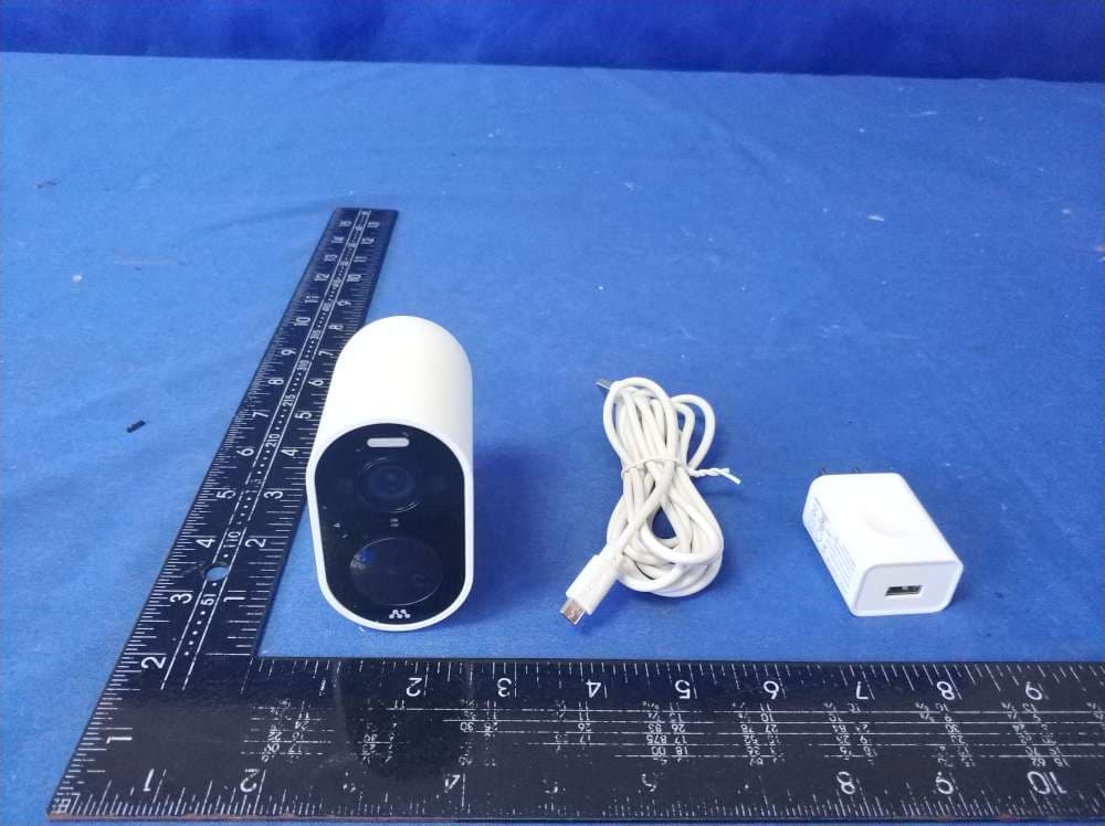
2AML4-MOCAMOUT
Aug 20, 20201080P HD WiFi Battery Camera
Equipment Class
DTS - Digital Transmission System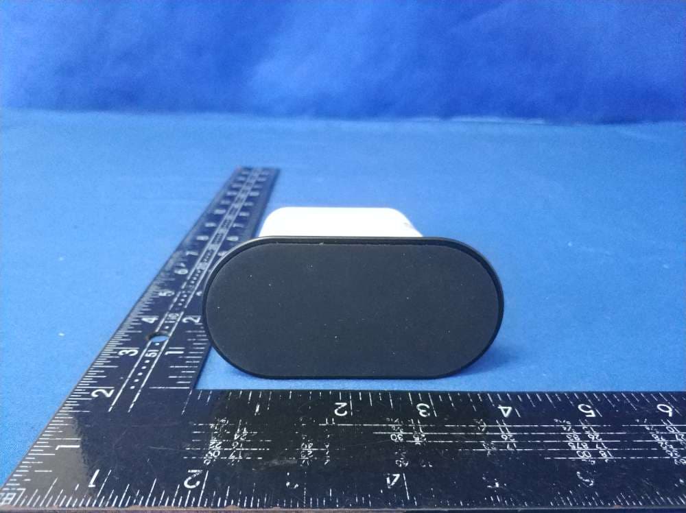
2AML4-CAM1080
Aug 20, 2020Battery Camera Hub
Equipment Class
DTS - Digital Transmission System