2AMPF-MX1902MX1902
MatchX GmbH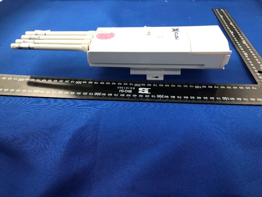
Click to zoom
Application Details
- Equipment Class
- DSS - Part 15 Spread Spectrum Transmitter
- Date of Grant
- Jan 05, 2021
- Application Purpose
- Original Equipment
- Date of Application
- Dec 29, 2020
- Equipment Note
- MX1902
- Frequency Range
- 902.30000000 - 927.70000000
- Company
- MatchX GmbH
- Country
- Germany
Documents & Files
Document Text
Text extracted from the exhibit documents filed with the FCC. Open a document above to read the original.
Users Manual
MatchX M2 Pro 16 Channels LPWAN Gateway User Guide Copyright © 2017 MatchX Inc./MatchX GmbH WWW.MATCHX.IO No part of the specifications may be reproduced in any form or by any means or used to make any derivative such as translation, transformation, or adaptation without permission from MatchX Inc./MatchX GmbH All rights reserved. Release 1.1, December 2020 Contents 1Introduction. . . . . . . . . . . . . . . . . . . . . . . . . . . . . . . . . . . . . . . . . . . . . . . . . . . . 5 1.1Product overview5 1.2Product overview6 1.2.1LoRa . . . . . . . . . . . . . . . . . . . . . . . . . . . . . . . . . . . . . . . . . . . . . . . . . . . . . . . . . . . . 6 1.2.2WiFi . . . . . . . . . . . . . . . . . . . . . . . . . . . . . . . . . . . . . . . . . . . . . . . . . . . . . . . . . . . . . 6 1.2.3GPS . . . . . . . . . . . . . . . . . . . . . . . . . . . . . . . . . . . . . . . . . . . . . . . . . . . . . . . . . . . . 6 1.2.4Processor Subsystem . . . . . . . . . . . . . . . . . . . . . . . . . . . . . . . . . . . . . . . . . . . . . . . 6 1.3Interface and Connectors7 1.3.1Connector panel of the Gateway . . . . . . . . . . . . . . . . . . . . . . . . . . . . . . . . . . . . 7 1.3.2Led status . . . . . . . . . . . . . . . . . . . . . . . . . . . . . . . . . . . . . . . . . . . . . . . . . . . . . . . . 7 1.3.3Console access . . . . . . . . . . . . . . . . . . . . . . . . . . . . . . . . . . . . . . . . . . . . . . . . . . . 8 1.3.4Antenna connectors . . . . . . . . . . . . . . . . . . . . . . . . . . . . . . . . . . . . . . . . . . . . . . . 8 2Quick Installation Guide. . . . . . . . . . . . . . . . . . . . . . . . . . . . . . . . . . . . . . . . 9 2.1Software requirements9 2.2Hardware requirements9 2.3Power connection10 2.3.1PoE power supply . . . . . . . . . . . . . . . . . . . . . . . . . . . . . . . . . . . . . . . . . . . . . . . . . 10 2.3.2USB-C power supply . . . . . . . . . . . . . . . . . . . . . . . . . . . . . . . . . . . . . . . . . . . . . . . 10 2.4Accessing the Gateway and Internet connection11 2.4.1Ethernet connection . . . . . . . . . . . . . . . . . . . . . . . . . . . . . . . . . . . . . . . . . . . . . . 11 2.4.2WiFi connection . . . . . . . . . . . . . . . . . . . . . . . . . . . . . . . . . . . . . . . . . . . . . . . . . . 11 2.4.33G/4G/LTE Option . . . . . . . . . . . . . . . . . . . . . . . . . . . . . . . . . . . . . . . . . . . . . . . . 11 4 2.5Mounting11 2.5.1Wall Mounting . . . . . . . . . . . . . . . . . . . . . . . . . . . . . . . . . . . . . . . . . . . . . . . . . . . 12 2.5.2Pole mounting . . . . . . . . . . . . . . . . . . . . . . . . . . . . . . . . . . . . . . . . . . . . . . . . . . . 12 2.6Surge protection and Shielded Ethernet cable13 3Product specification. . . . . . . . . . . . . . . . . . . . . . . . . . . . . . . . . . . . . . . . . . 14 3.1Hardware Specification14 3.2WiFi specification15 3.3LoRa Radio specification15 3.4GPS Antenna Performance16 3.5LoRa Antenna Performance16 3.6Operational frequencies16 4Package content. . . . . . . . . . . . . . . . . . . . . . . . . . . . . . . . . . . . . . . . . . . . . . 18 5Revision History. . . . . . . . . . . . . . . . . . . . . . . . . . . . . . . . . . . . . . . . . . . . . . . . 19 6Important Notice. . . . . . . . . . . . . . . . . . . . . . . . . . . . . . . . . . . . . . . . . . . . . . 20 6.1Legal notice20 6.2FCC regulatory conformance - applies to MX190220 6.3IC regulatory conformance - applies to MX190221 1.Introduction 1.1 Product overview MX190x is an outdoor LPWAN gateway equipped with dual LoRa radio capable of simultaneously receive on 16 frequency channels. It is based on the newest SX1302 LoRaWAN Gateway chip which allows it to use spreading factors from SF5 to SF12. This greatly improves the throughput and decreases the data collisions in dense networks with many sensor nodes compared with previous generation of gateways based on older SX1301. Improvement on performance comes together with significant reduction of power consumption which reduces the cost of operation and increases long time reliability of the devices. This guide covers the MX1901 and MX1902 version of MatchX M2 Pro Gateway, with the MatchX LPWAN controller version 1.0 or above. The main differences between them are listed in the Table 1.1: ItemMX1902MX1901 Band902-928MHz863-873MHz Maximum Conducted Power+27dBm+27dBm LBTYesYes No. of Channels1616 SF5-105-12 CertificationIEC 60950 -1EN 300200 FCC PART 15.247EN 301489 IP RatingIP66IP66 Table 1.1: Comparison of MX1901 and MX1902 6Chapter 1. Introduction 1.2 Product overview • Dual LoRa radio with 16 Rx channels • Half duplex LoRa communication with 2 Tx paths • 2 LoRa antenna connectors • Build in GNSS receiver with GNSS engine for GPS/QZSS, GLONASS • Build in WiFi module with full function of 802.11b/g/n over 2.4GHz • 100Mbase Ethernet connection with passive PoE 24V power supply • USB-C interface for debug with Power Delivery capability for power supply • USB-A general purpose interface • Internal storage on SD-Card or optional flash SSD • Secure element for key storage, secure boot and provisioning • Accelerometer and pressure sensor for temper detection • Auto diagnostic functions • IP66, outdoor enclosure • Industrial temperature range -40 ◦ C to +85 ◦ C 1.2.1 LoRa The MatchX M2 Pro fully supports LoRaWAN protocol, covering a massive vicinity of up to 20km+ in open spaces. Thanks to 16 frequencies channels and Spreading Factors as low as SF5 this gateway provides exceptionally good coverage in places with huge number of sensor devices. Based on the newest LoRa chipset SX1302 the Gateway is able to simultaneously demodulated more data packets then it was possible before reducing data collision and allowing for more dense sensor deployment in applications like smart farming, home automation or asset tracking. 1.2.2 WiFi The MX1901/2 Gateways provide build in WiFi connectivity according to 2.4GHz 802.11b/g/n specification. Thanks to build in antenna no extra installation is need…
Text truncated - open the document above for the full version.
Cover Letter(s)
Date: 21 December 2020 MatchX GmbH To: Federal Communications Commission, Authorization & Evaluation Division, 7435 Oakland Mills Road, Columbia, MD 21046 To Whom It May Concern: The MatchX GmbH, the undersigned, hereby authorizes Mr. Wu Xuewen from Shenzhen BALUN Technology Co., Ltd., to act on the behalf of the MatchX GmbH solely in matters relating to the application for an FCC equipment authorization for FCC ID: 2AMPF-MX1902 including the signing of documents in connection with this Application. Necessary acts carried out by Shenzhen BALUN Technology Co., Ltd. in connection with the Application shall have the same effect as acts of the MatchX GmbH. The MatchX GmbH also hereby certify that no party to this application is subject to a denial of benefits, including FCC benefits, pursuant to Section 5301 of the Anti-Drug Abuse Act of 1988, 21 U.S.C. Section 862. Yours Sincerely, _______ XinHu
Cover Letter(s)
Date: 21 December 2020 MatchX GmbH To: Federal Communications Commission, Authorization & Evaluation Division, 7435 Oakland Mills Road, Columbia, MD 21046 Re: MatchX GmbH FCC ID: 2AMPF-MX1902 FCC Certification Confidentiality Request Gentlemen: This letter is to comply with 47 CFR 0.457 and 0.459 pertaining to confidentiality material. MatchX GmbH requests that the following documents regarding this submission for FCC ID: 2AMPF-MX1902 be kept confidential: Exhibit Type File Name Block Diagram Block Diagram.pdf Schematics Schematics.pdf Operational Description Operational Description.pdf And below exhibit kept short-term confidential (180 days): External photos External photos.pdf Te s t setup photos test photo.pdf Internal photos Internal photos.pdf User manual User manual.pdf Those documents contain detailed system and equipment description and related information about the product which MatchX GmbH considers to be confidential proprietary, a custom design and, otherwise, not releasable to the general public. Since this design is a basis form which future technological products will evolve, MatchX GmbH considers this information would be of benefit to its competitors, and that the disclosure of the information in these documents would give competitors an unfair advantage in the market. Yours Sincerely, XinHu
External Photos
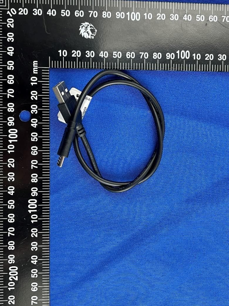
Annex No.: BL-SZ2080345-AW 1 / 5 EUT EXTERNAL PHOTOS FRONT VIEW OF EUT b REAR VIEW OF EUT Annex No.: BL-SZ2080345-AW 2 / 5 LEFT SIDE VIEW OF EUT RIGHT SIDE OF EUT X Annex No.: BL-SZ2080345-AW 3 / 5 TOP VIEW OF EUT c BOTTOM VIEW OF EUT Annex No.: BL-SZ2080345-AW 4 / 5 Accessory-Power Line CLOSE-UP Annex No.: BL-SZ2080345-AW 5 / 5 Accessory-Antenna
ID Label/Location Info
Label: Label location: Label
Internal Photos
Annex No.: BL-SZ2080345-AI 1 / 4 EUT INTERNAL PHOTOS EUT UNCOVER VIEW Close-up Annex No.: BL-SZ2080345-AI 2 / 4 EUT UNCOVER VIEW EUT UNCOVER VIEW Annex No.: BL-SZ2080345-AI 3 / 4 MAIN BOARD TOP VIEW (WITH SHIELDING) MAIN BOARD REAR VIEW Ceramic Chip ANTENNA Annex No.: BL-SZ2080345-AI 4 / 4 MAIN BOARD TOP VIEW (WITHOUT SHIELDING)
RF Exposure Info
RF Exposure Evaluation For FCC ID: 2AMPF-MX1902 Refer user manual this device is a MX1902, and this device was designed used in Mobile devices that the minimum distance between human’s body is 25cm. Based on the 47CFR 2.1091, this device belongs to Mobile device. The definition of the category as following: Mobile Derives: CFR Title 47 §2.1091(b) (b) For purposes of this section, a mobile device is defined as a transmitting device designed to be used in other than fixed locations and to generally be used in such a way that a separation distance of at least 20 centimeters is normally maintained between the transmitter’s radiating structure(s) and the body of the user or nearby persons. FCC KDB 447498 D01 General RF Exposure Guidance v06 Limit Devices operating in standalone mobile exposure conditions may contain a single transmitter or multiple transmitters that do not transmit simultaneously. A minimum test separation distance ≥ 20 cm is required between the antenna and radiating structures of the device and nearby persons to apply mobile device exposure limits. The distance must be fully supported by the operating and installation configurations of the transmitter and its antenna(s), according to the source-based time-averaged maximum power requirements of § 2.1091(d)(2). In cases where cable losses or other attenuations are applied to determine compliance, the most conservative operating configurations and exposure conditions must be evaluated. The minimum test separation distance required for a device to comply with mobile exposure conditions must be clearly identified in the installation and operating instructions, for all installation and exposure conditions, to enable users and installers to comply with RF exposure requirements. For mobile devices that have the potential to operate in portable device exposure conditions, similar to the configurations described in § 2.1091(d)(4), a KDB inquiry is required to determine the SAR test requirements for demonstrating compliance. When the categorical exclusion provision of § 2.1091(c) applies, the minimum test separation distance may be estimated, when applicable, by simple calculations according to plane-wave equivalent conditions, to ensure the transmitter and its antenna(s) can operate in manners that meet or exceed the estimated distance. The source-based time-averaged maximum radiated power, according to the maximum antenna gain, must be applied to calculate the field strength and power density required to establish the minimum test separation distance. When the estimated test separation distance becomes overly conservative and does not support compliance, MPE measurement or computational modeling may be used to determine the required minimum separation distance. According to FCC Part 1.1307, systems operating under the provisions of this section shall be operated in a manner the ensures that the public is not exposed to radio frequency energy level in excess of the commission’s guidelines. Limits for General Population/ Uncontrolled Exposure Frequency Range (MHz) Electric Field Strength(E)(V/m) Magnetic Field Strength (H)(A/m) Power Density (S)(mW/cm 2 ) 0.3-1.34 614 1.63 (100)* 1.34-30 824/f 2.19/f (180/f2)* 30-300 27.5 0.073 0.2 300-1500 f/1500 1500-100,000 1.0 MPE calculation formula Where: S = power density P = output power (mW) G = power gain of the antenna in the direction of interest relative to an isotropic radiator R = Separation distance between radiator and human body (cm) Test data 2.4G WIFI Mode 802.11b 802.11g 802.11n20 Low Middle High Low MiddleHigh Low MiddleHigh Peak power (dBm) 18.10 18.48 17.58 21.08 23.28 23.48 22.74 23.12 20.56 Note: This report listed the worst case EIRP/ERP value, please refer to RF test report for more details. LoRa 125KHz (Main Antenna) Mode Low Channel Middle Channel High Channel Peak Power (dBm) 26.11 24.54 23.72 125KHz (Aux. Antenna) Mode Low Channel Middle Channel High Channel Peak Power (dBm) 26.11 24.70 24.04 500KHz (Main Antenna) Mode Low Channel Middle Channel High Channel Peak Power (dBm) 26.19 24.44 23.50 500KHz (Aux. Antenna) Mode Low Channel Middle Channel High Channel Peak Power (dBm) 26.07 24.93 24.47 Note: This report listed the worst case peak power value, please refer to RF test report for more details. Turn-up power Mode Range (dBm) 2.4G WIFI 802.11b 17.50-18.50 802.11g 21.00-23.50 802.11n20 20.50-23.50 LoRa (125KHz) (Main Antenna) 23.50-26.50 LoRa (125KHz) (Aux. Antenna) 23.50-26.50 LoRa (500KHz) (Main Antenna) 23.50-26.50 LoRa (500KHz) (Aux. Antenna) 23.50-26.50 Test result Evolution mode Maximum peak output power (dBm) Antenna Gain (typical) (dBi) To t a l Power (mw) Distance (cm) Power Density (mW/cm²) Limit of Power Density (mW/cm²) Power Density / Limit Verdict 2.4G WIFI 23.50 2.0 223.87 25 0.045 1.00 0.045 Pass LoRa (Main) 26.50 2.1 724.44 25 0.092 0.6013 0.153 Pass LoRa (Aux.) 26.50 2.1 724.44 25 0.092 0.6013 0.153 Pass Collocated Power Density Calculation Evolution mode Frequency(MHz) Power Density/Limit Σ(Power Density / Limit) of WLAN + Lora Verdict 2.4G WIFI 2400 MHz ~ 2483.5 MHz 0.045 0.198 Pass Lora (Main) 902 MHz ~ 928 MHz 0.153 Pass Evolution mode Frequency(MHz) Power Density/Limit Σ(Power Density / Limit) of WLAN + Lora Verdict 2.4G WIFI 2400 MHz ~ 2483.5 MHz 0.045 0.198 Pass Lora (Aux.) 902 MHz ~ 928 MHz 0.153 Pass Note: 1. Σ(Power Density / Limit): This is a summation of [(power density for each transmitter/ antenna included in the simultaneous transmission)/ (corresponding MPE limit)]. 2. The formula of calculated the MPE is CPD1 / LPD1 + CPD2 / LPD2 + ......etc. < 1 CPD = Calculation power density LPD = Limit of power density 3. The worst-case situation is 0.198, which is less than “1”. This confirmed that the device comply with FCC 1.1310 MPE limit. 4. The MX1902 work frequency range used is 902 MHz ~ 928 MHz and 2400 MHz ~ 2483.5 MHz, the result close to the limit by the above formula, so we select 2400 MHz and 902MHz to calculate the exclusion power t…
Text truncated - open the document above for the full version.
Test Report
Report No.: BL-SZ2080345-602 2 / 145 TABLE OF CONTENTS 1 ADMINISTRATIVE DATA (GENERAL INFORMATION) .......................................................................... 7 1.1 Identification of the Testing Laboratory ....................................................................................... 7 1.2 Identification of the Responsible Testing Location ...................................................................... 7 1.3 Laboratory Condition ................................................................................................................... 7 1.4 Announce .................................................................................................................................... 8 2 PRODUCT INFORMATION ...................................................................................................................... 9 2.1 Applicant Information ................................................................................................................... 9 2.2 Manufacturer Information ............................................................................................................ 9 2.3 Factory Information ..................................................................................................................... 9 2.4 General Description for Equipment under Test (EUT) ................................................................ 9 2.5 Technical Information ................................................................................................................ 10 2.6 Additional Instructions ............................................................................................................... 13 3 SUMMARY OF TEST RESULTS ............................................................................................................ 14 3.1 Test Standards .......................................................................................................................... 14 3.2 Verdict ....................................................................................................................................... 15 4 GENERAL TEST CONFIGURATIONS ................................................................................................... 16 4.1 Test Environments .................................................................................................................... 16 4.2 Test Equipment List ................................................................................................................... 16 4.3 Measurement Uncertainty ......................................................................................................... 17 4.4 Description of Test Setup .......................................................................................................... 17 4.4.1 For Antenna Port Test ............................................................................................................... 17 4.4.2 For AC Power Supply Port Test ................................................................................................ 1 8 4.4.3 For Radiated Test (Below 30 MHz) ........................................................................................... 18 4.4.4 For Radiated Test (30 MHz-1 GHz) .......................................................................................... 19 4.4.5 For Radiated Test (Above 1 GHz) ............................................................................................. 19 4.5 Measurement Results Explanation Example ............................................................................. 20 Revision History Version Issue Date Revisions Content Rev. 01 Dec. 22, 2020 Initial Issue Report No.: BL-SZ2080345-602 3 / 145 4.5.1 For conducted test items: .......................................................................................................... 20 5 TEST ITEMS - Hybrid ............................................................................................................................. 21 5.1 Antenna Requirements .............................................................................................................. 21 5.1.1 Relevant Standards ................................................................................................................... 21 5.1.2 Antenna Anti-Replacement Construction .................................................................................. 21 5.1.3 Antenna Gain ............................................................................................................................ 21 5.2 Peak Output Power and E.I.R.P ................................................................................................ 2 2 5.2.1 Test Limit ................................................................................................................................... 22 5.2.2 Test Setup ................................................................................................................................. 22 5.2.3 Test Procedure .......................................................................................................................... 22 5.2.4 Test Result ................................................................................................................................ 22 5.3 Occupied Bandwidth ................................................................................................................. 23 5.3.1 Limit ........................................................................................................................................... 23 5.3.2 Test Setup ................................................................................................................................. 23 5.3.3 Test Procedure .......................................................................................................................... 23 5.3.4 Test Result ................................…
Text truncated - open the document above for the full version.
Test Setup Photos
Annex No.: BL-SZ2080345-AR 1 / 6 TEST SETUP PHOTOS 1 Radiated Test Photo Below 30MHz 30MHz-1 GHz-WiFi Annex No.: BL-SZ2080345-AR 2 / 6 Close-up-WiFi 30MHz-1 GHz-LoRa Annex No.: BL-SZ2080345-AR 3 / 6 Close-up-LoRa Above 1GHz Annex No.: BL-SZ2080345-AR 4 / 6 Close-up 2 Conducted Test Photo Conducted Test-WiFi Annex No.: BL-SZ2080345-AR 5 / 6 Conducted Test-LoRa 3 Conducted Emissions Test Photo 1 Annex No.: BL-SZ2080345-AR 6 / 6 Test Photo 2
Contact Information
Applicant
Xin Hu(Lead Hardware Engineer)
Technical Contact
Shenzhen BALUN Technology Co., Ltdxuewen wu
[email protected]86-755-66850100
Block B, FL 1, Baisha Science and Technology Park, · China
Non-Technical Contact
Shenzhen BALUN Technology Co., LtdTiffany Zhang
[email protected]86-755-66850100
Test Firm
Shenzhen BALUN Technology Co., Ltd.Hanson Lin
[email protected]86-755-66833830
Technical Specifications
| # | Rule Parts | Frequency Range | Power Output |
|---|---|---|---|
| 1 | 15C | 902.3 MHz - 927.7 MHz | 410.00 mW |
Other Applications from MatchX GmbH
2AMPF-MX2311
Apr 04, 2023NEO
Equipment Class
DTS - Digital Transmission System