2AMWOFSC-BT806ABluetooth Module
Shenzhen Feasycom Co.,Ltd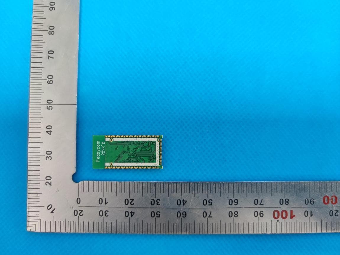
Click to zoom
Application Details
- Equipment Class
- DSS - Part 15 Spread Spectrum Transmitter
- Date of Grant
- May 20, 2021
- Application Purpose
- Original Equipment
- Date of Application
- May 20, 2021
- Equipment Note
- Bluetooth Module
- Frequency Range
- 2402.00000000 - 2480.00000000
- Company
- Shenzhen Feasycom Co.,Ltd
- Country
- China
Documents & Files
Document Text
Text extracted from the exhibit documents filed with the FCC. Open a document above to read the original.
Users Manual
FSC-BT806 Datasheet Shenzhen Feasycom Technology Co.,Ltd www.feasycom.com -1- FSC-BT806A 5.0 Dual Mode Bluetooth Module Datasheet Version 1.2 FSC-BT806 Datasheet Shenzhen Feasycom Technology Co.,Ltd www.feasycom.com -2- Copyright © 2013-2019 Feasycom Technology. All Rights Reserved. Feasycom Technology reserves the right to make corrections, modifications, and other changes to its products, documentation and services at anytime. Customers should obtain the newest relevant information before placing orders. To minimize customer product risks, customers should provide adequate design and operating safeguards. Without written permission from Feasycom Technology, reproduction, transfer, distribution or storage of part or all of the contents in this document in any form is prohibited. Revision History Version Data Notes 1.0 2018/05/25 Initial Version Devin Wan 1.1 2019/10/22 1. Add Ordering Information and modify some incorrect descriptions 2. Update General Specifications Devin Wan 1.2 2020/03/25 Update module picture, block diagram Devin Wan Contact Us Shenzhen Feasycom Technology Co.,LTD Email: [email protected] Address: Room 2004-2005,20th Floor,Huichao Technology Building,Jinhai Road, Xixiang ,Baoan District,Shenzhen,518100,China. Tel: 86-755-27924639, 86-755-23062695 FSC-BT806 Datasheet Shenzhen Feasycom Technology Co.,Ltd www.feasycom.com -3- Contents 1. INTRODUCTION ............................................................................................................................................................... 5 2. GENERAL SPECIFICATION ................................................................................................................................................. 7 3. HARDWARE SPECIFICATION .......................................................................................................................................... 8 3.1 PIN DEFINITION DESCRIPTIONS ................................................................................................................................................. 9 4. PHYSICAL INTERFACE ..................................................................................................................................................... 12 4.1 POWER MANAGEMENT .......................................................................................................................................................... 12 4.1.1 Power Supply ............................................................................................................................................................ 12 4.1.2 Battery Charger ........................................................................................................................................................ 12 4.1.2.1 Battery Charger Hardware Operating Modes ....................................................................................................... 12 4.1.2.2 Battery Charger Trimming and Calibration ........................................................................................................... 14 4.1.2.3 VM Battery Charger Control.................................................................................................................................. 14 4.1.2.4 Battery Charger Firmware and PS Keys ................................................................................................................. 14 4.2 RESET ................................................................................................................................................................................. 14 4.2.1 Digital Pin States on Reset........................................................................................................................................ 15 4.2.2 Status After Reset ..................................................................................................................................................... 15 4.2.3 Automatic Reset Protection ..................................................................................................................................... 15 4.3 GENERAL PURPOSE ANALOG IO ............................................................................................................................................... 16 4.4 GENERAL PURPOSE DIGITAL IO ................................................................................................................................................ 16 4.5 RF INTERFACE ...................................................................................................................................................................... 16 4.6 SERIAL INTERFACES ................................................................................................................................................................ 16 4.6.1 UART Interface ......................................................................................................................................................... 16 4.6.2 I 2 C Interface .............................................................................................................................................................. 18 4.6.3 USB Interface ............................................................................................................................................................ 18 4.7 LED DRIVERS ....................................................................................................................................................................... 19 4.8 AUDIO INTERFACES ................................................................................................................................................................ 20 4.8.1 Audio Input and Output ........................................................................................................................................... 21 4.8.2 Audio Codec Interface .............…
Text truncated - open the document above for the full version.
Cover Letter(s)
Shenzhen Feasycom Technology Co., LTD Room 2004A, 20th Floor, Huichao Technology Building, Jinhai Road, Xixiang, Baoan District, Shenzhen, China Agent Authorization Company: Shenzhen Feasycom Technology Co., LTD Address: Room 2004A, 20th Floor, Huichao Technology Building, Jinhai Road, Xixiang, Baoan District, Shenzhen, China Product Name: Bluetooth Module Model Number(s): FSC-BT806A Product Description: Bluetooth Module We authorize MiCOM Labs Inc., 575 Boulder Court, Pleasanton, California 94566, USA, to act on our behalf on all matters concerning the certification of above named equipment. We declare that MiCOM Labs Inc. is allowed to forward all information related to the approval and certification of equipment to the regulatory agencies as required and to discuss any issues concerning the approval application. Any and all acts carried out by MiCOM Labs on our behalf shall have the same effect as acts of our own. Signature: Date: Apr.30, 2021 Name: Wan Zhifu Title: General Manager Company: Shenzhen Feasycom Technology Co., LTD
Cover Letter(s)
Shenzhen Feasycom Technology Co., LTD Room 2004A, 20th Floor, Huichao Technology Building, Jinhai Road, Xixiang, Baoan District, Shenzhen, China RE FCC ID: 2AMWOFSC-BT806A To the certification reviewer: We are hereby applying for [full] modular approval of the above-referenced FCC ID, based on compliance with [all] of the criteria as detailed below. Sincerely, [Wan Zhifu] [General Manager] Part 15 Unlicensed Single Modular Transmitter Approval Justification per 15.212 Requirement per 15.212 reference (i) The radio elements of the modular transmitter must have their own RF shielding. Shielding is provided by a metal cover over the circuitry. (ii) The modular transmitter must have buffered modulation/data inputs (if such inputs are provided. All modulation and data inputs are buffered by circuitry on the transmitter chip. (iii) The modular transmitter must have its own power supply regulation. Power supply regulation is provided by circuitry on the transmitter chip. (iv) The modular transmitter must comply with the antenna and transmission system requirements of §§ 15.203, 15.204(b) and 15.204(c). The antenna is fixed. (v) The modular transmitter must be tested in a stand-alone configuration, i.e., the module must not be inside another device during testing for compliance with Part 15 parameters. Testing was performed in a stand-alone configuration as shown in the test setup photos. (vi) The modular transmitter must be equipped with either a permanently affixed label or must be capable of electronically displaying its FCC identification number. If the FCC ID is not visible when the module is installed inside another device, then the outside of the device into which the module is installed must also display a label referring to the enclosed module. The modular was labeled with its own FCC ID. The outside of device in to which the module is installed will labeled Contains TX FCC ID: 2AMWOFSC- BT806A, Please refer to User Manual. Shenzhen Feasycom Technology Co., LTD Room 2004A, 20th Floor, Huichao Technology Building, Jinhai Road, Xixiang, Baoan District, Shenzhen, China (vii) The modular transmitter must comply with any specific rules or operating requirements that ordinarily apply to a complete transmitter and the manufacturer must provide adequate instructions along with the module to explain any such requirements. A copy of these instructions must be included in the application for equipment authorization. The modular is comply with all applicable FCC rules. Any modifications, not expressly approved by the manufacturer could void the authority to operate in these regions. (viii) The modular transmitter must comply with any applicable RF exposure requirements in its final configuration. This module operates under Part 15 .247 which is exempt from RF exposure evaluation owing to the very low operating power.
External Photos
External Photos Test Model: FSC-BT806A TOP VIEW OF EUT BOTTOM VIEW OF EUT FRONT VIEW OF EUT BACK VIEW OF EUT LEFT VIEW OF EUT RIGHT VIEW OF EUT
ID Label/Location Info
FCC ID and IC Label Location 8mm*5mm FCC ID: 2AMWOFSC-BT806A IC: 23872-FSCBT806A FSC-BT806A
Internal Photos
Internal Photos Test Model: FSC-BT806A OPEN VIEW OF EUT INTERNAL VIEW OF EUT-1 BT Antenna INTERNAL VIEW OF EUT-2
RF Exposure Info
RF EXPOSURE EVALUATION 1. PRODUCT INFORMATION Product Description Bluetooth Module Model Name FSC-BT806A FCC ID 2AMWOFSC-BT806A 2. EVALUATION METHOD AND LIMIT Human exposure to RF emissions from mobile devices (47 CFR §2.1091) may be evaluated based on the MPE limits adopted by the FCC for electric and magnetic field strength and/or power density, as appropriate, since exposures are assumed to occur at distances of 20 cm or more from persons. LIMITS FOR GENERAL POPULATION / UNCONTROLLED EXPOSURE Frequency Range (MHz) E-field Strength (E) (V/m) Magnetic Field Strength (H) (A/m) Power Density (S) (mW/cm 2 ) Averaging Time |E| 2 , |H| 2 or S (Minutes) 0.3 -- 1.34 614 1.63 (100)* 30 1.34 -- 30 824/f 2.19/f (180/f 2 )* 30 30 -- 300 27.5 0.073 0.2 30 300 -- 1500 -- -- f/1500 30 1500 -- 100,000 -- -- 1.0 30 *Note: 1. f= Frequency in MHz * Plane-wave Equivalent Power Density 2. The averaging time for General Population/Uncontrolled exposure to fixed transmitters is not applicable for mobile and portable transmitters. See 47 CFR §§2.1091 and 2.1093 on source-based time-averaging requirement for mobile and portable transmitters. S=PG/4πR² Where: S=power density P=power input to antenna G=power gain of the antenna in the direction of interest relative to an isotropic radiator R=distance to the center of radiation of the antenna 3. CALCULATION A minimum test separation distance ≥ 20 cm is required between the antenna and radiating structures of the device and nearby persons to apply mobile device exposure limits. The distance must be at least 20 cm and fully supported by the operating and installation configurations of the transmitter and its antenna(s), according to the source-based time-averaged maximum power requirements of § 2.1091(d)(2). In cases where cable losses or other attenuations are applied to determine compliance, the most conservative operating configurations and exposure conditions must be evaluated. BT Antenna Gain=2dBi (Numeric 1.58), π=3.14 Note:Only the worst case recorded. 4. CONCLUSION Compliance the RF exposure requirement Frequency Output Power Output Power Power Density Power Density Limit MHz dBm mW mW/cm 2 mW/cm 2 2480(BR/EDR) 8.704 7.42 0.00233 1 2480(BLE) 8.521 7.11 0.00224 1
Test Report
Page 1 of 69 FCC Test Report Report No.: AGC03285210303FE03 FCC ID : 2AMWOFSC-BT806A APPLICATION PURPOSE : Original Equipment PRODUCT DESIGNATION : Bluetooth Module BRAND NAME : Feasycom MODEL NAME : FSC-BT806A APPLICANT : Shenzhen Feasycom Technology Co., LTD DATE OF ISSUE : Apr. 26, 2021 STANDARD(S) : FCC Part 15.247 REPORT VERSION : V1.0 Attestation of Global Compliance (Shenzhen) Co., Ltd Report No.: AGC03285210303FE03 Page 2 of 69 REPORT REVISE RECORD Report Version Revise Time Issued Date Valid Version Notes V1.0 / Apr. 26, 2021 Valid Initial Release Report No.: AGC03285210303FE03 Page 3 of 69 TABLE OF CONTENTS 1. VERIFICATION OF CONFORMITY .................................................................................................................. 5 2. GENERAL INFORMATION .............................................................................................................................. 6 2.1. PRODUCT DESCRIPTION ........................................................................................................................ 6 2.2. TABLE OF CARRIER FREQUENCYS ....................................................................................................... 6 2.3. RECEIVER INPUT BANDWIDTH .............................................................................................................. 7 2.4. EXAMPLE OF A HOPPING SEQUENCY IN DATA MODE ......................................................................... 7 2.5. EQUALLY AVERAGE USE OF FREQUENCIES AND BEHAVIOUR ......................................................... 7 2.6. RELATED SUBMITTAL(S) / GRANT (S) .................................................................................................... 8 2.7. TEST METHODOLOGY ............................................................................................................................. 8 2.8. SPECIAL ACCESSORIES ......................................................................................................................... 8 2.9. EQUIPMENT MODIFICATIONS ................................................................................................................. 8 2.10. ANTENNA REQUIREMENT..................................................................................................................... 8 3. MEASUREMENT UNCERTAINTY ................................................................................................................... 9 4. DESCRIPTION OF TEST MODES ................................................................................................................. 10 5. SYSTEM TEST CONFIGURATION ................................................................................................................ 11 5.1. CONFIGURATION OF EUT SYSTEM ...................................................................................................... 11 5.2. EQUIPMENT USED IN TESTED SYSTEM .............................................................................................. 11 5.3. SUMMARY OF TEST RESULTS .............................................................................................................. 11 6. TEST FACILITY .............................................................................................................................................. 12 7. PEAK OUTPUT POWER ................................................................................................................................ 13 7.1. MEASUREMENT PROCEDURE ............................................................................................................. 13 7.2. TEST SET-UP (BLOCK DIAGRAM OF CONFIGURATION) .................................................................... 13 7.3. LIMITS AND MEASUREMENT RESULT .................................................................................................. 14 8. 20DB BANDWIDTH ........................................................................................................................................ 20 8.1. MEASUREMENT PROCEDURE ............................................................................................................. 20 8.2. TEST SET-UP (BLOCK DIAGRAM OF CONFIGURATION) .................................................................... 20 8.3. LIMITS AND MEASUREMENT RESULTS ............................................................................................... 21 9. CONDUCTED SPURIOUS EMISSION........................................................................................................... 27 9.1. MEASUREMENT PROCEDURE ............................................................................................................. 27 Report No.: AGC03285210303FE03 Page 4 of 69 9.2. TEST SET-UP (BLOCK DIAGRAM OF CONFIGURATION) .................................................................... 27 9.3. MEASUREMENT EQUIPMENT USED .................................................................................................... 27 9.4. LIMITS AND MEASUREMENT RESULT .................................................................................................. 27 10. RADIATED EMISSION ................................................................................................................................. 40 10.1. MEASUREMENT PROCEDURE ........................................................................................................... 40 10.2. TEST SETUP ......................................................................................................................................... 42 10.3. LIMITS AND MEASUREMENT RESULT ............................................................................................... 43 10.4. TEST RESULT........................................................................................................................................ 43 11. NUMBER OF HOPPING FREQUENCY ...........................................................…
Text truncated - open the document above for the full version.
Test Report
Report No.: AGC03285210303FE03 Page 51 of 69 EUT Bluetooth Module Model Name FSC-BT806A Temperature 25°C Relative Humidity 55.4% Pressure 960hPa Test Voltage Normal Voltage Test Mode Mode 3 Antenna Horizontal PK AV RESULT: PASS Report No.: AGC03285210303FE03 Page 52 of 69 EUT Bluetooth Module Model Name FSC-BT806A Temperature 25°C Relative Humidity 55.4% Pressure 960hPa Test Voltage Normal Voltage Test Mode Mode 3 Antenna Vertical PK AV RESULT: PASS Note: The factor had been edited in the “Input Correction” of the Spectrum Analyzer. The GFSK modulation is the worst case and recorded in the report. Report No.: AGC03285210303FE03 Page 53 of 69 11. NUMBER OF HOPPING FREQUENCY 11.1. MEASUREMENT PROCEDURE The EUT shall have its hopping function enabled. Use the following spectrum analyzer settings: 1. Span: The frequency band of operation. Depending on the number of channels the device supports, it may be necessary to divide the frequency range of operation across multiple spans, to allow the individual channels to be clearly seen. 2. RBW: To identify clearly the individual channels, set the RBW to less than 30% of the channel spacing or the 20 dB bandwidth, whichever is smaller. 3. VBW ≥ RBW. Sweep: Auto. Detector function: Peak. Trace: Max hold. 4. Allow the trace to stabilize. 11.2. TEST SETUP (BLOCK DIAGRAM OF CONFIGURATION) Same as described in section 8.2 11.3. MEASUREMENT EQUIPMENT USED The same as described in section 6 11.4. LIMITS AND MEASUREMENT RESULT TOTAL NO. OF HOPPING CHANNEL LIMIT (NO. OF CH) MEASUREMENT (NO. OF CH) RESULT >=15 79 PASS TEST PLOT FOR NO. OF TOTAL CHANNELS Note: The GFSK modulation is the worst case and recorded in the report. Report No.: AGC03285210303FE03 Page 54 of 69 12. TIME OF OCCUPANCY (DWELL TIME) 12.1. MEASUREMENT PROCEDURE The EUT shall have its hopping function enabled. Use the following spectrum analyzer settings: 1. Span: Zero span, centered on a hopping channel. 2. RBW shall be≤channel spacing and where possible RBW should be set >> 1 / T, where T is the expected dwell time per channel. 3. Sweep: As necessary to capture the entire dwell time per hopping channel; where possible use a video trigger and trigger delay so that the transmitted signal starts a little to the right of the start of the plot. The trigger level might need slight adjustment to prevent triggering when the system hops on an adjacent channel; a second plot might be needed with a longer sweep time to show two successive hops on a channel. 4. Detector function: Peak. Trace: Max hold. 5. Use the marker-delta function to determine the transmit time per hop. 6. Repeat the measurement using a longer sweep time to determine the number of hops over the period specified in the requirements. The sweep time shall be equal to, or less than, the period specified in the requirements. Determine the number of hops over the sweep time and calculate the total number of hops in the period specified in the requirements, using the following equation: (Number of hops in the period specified in the requirements) = (number of hops on spectrum analyzer) × (period specified in the requirements / analyzer sweep time) 7. The average time of occupancy is calculated from the transmit time per hop multiplied by the number of hops in the period specified in the requirements. 12.2. TEST SETUP (BLOCK DIAGRAM OF CONFIGURATION) Same as described in section 8.2 12.3. MEASUREMENT EQUIPMENT USED The same as described in section 6 12.4. LIMITS AND MEASUREMENT RESULT Channel Time of Pulse for DH5 (ms) Number of hops in the period specified in the requirements Sweep Time (ms) Limit (ms) Low 2.896 27*4 312.811 400 Middle 2.897 27*4 312.879 400 High 2.897 27*4 312.855 400 Note: The GFSK modulation is the worst case and recorded in the report. Report No.: AGC03285210303FE03 Page 55 of 69 TEST PLOT OF LOW CHANNEL Report No.: AGC03285210303FE03 Page 56 of 69 TEST PLOT OF MIDDLE CHANNEL Report No.: AGC03285210303FE03 Page 57 of 69 TEST PLOT OF HIGH CHANNEL Report No.: AGC03285210303FE03 Page 58 of 69 13. FREQUENCY SEPARATION 13.1. MEASUREMENT PROCEDURE The EUT shall have its hopping function enabled. Use the following spectrum analyzer settings: 1. Span: Wide enough to capture the peaks of two adjacent channels. 2. RBW: Start with the RBW set to approximately 30% of the channel spacing; adjust as necessary to best identify the center of each individual channel. 3. Video (or average) bandwidth (VBW) ≥ RBW. 4. Sweep: Auto. e) Detector function: Peak. f) Trace: Max hold. g) Allow the trace to stabilize. Use the marker-delta function to determine the separation between the peaks of the adjacent channels. 13.2. TEST SETUP (BLOCK DIAGRAM OF CONFIGURATION) Same as described in section 6.2 13.3. MEASUREMENT EQUIPMENT USED The same as described in section 6.3 13.4. LIMITS AND MEASUREMENT RESULT TEST MODE CHANNEL SEPARATION LIMIT RESULT MHz Pass Hopping Mode 1.001 >= 2/3 20 dB BW TEST PLOT FOR FREQUENCY SEPARATION Note: The GFSK modulation is the worst case and recorded in the report. Report No.: AGC03285210303FE03 Page 59 of 69 14. FCC LINE CONDUCTED EMISSION TEST 14.1. LIMITS OF LINE CONDUCTED EMISSION TEST Frequency Maximum RF Line Voltage Q.P. (dBμV) Average (dBμV) 150kHz~500kHz 66-56 56-46 500kHz~5MHz 56 46 5MHz~30MHz 60 50 Note: 1. The lower limit shall apply at the transition frequency. 2. The limit decreases linearly with the logarithm of the frequency in the range 0.15 MHz to 0.50 MHz. 14.2. BLOCK DIAGRAM OF LINE CONDUCTED EMISSION TEST EUT & Support Units Report No.: AGC03285210303FE03 Page 60 of 69 14.3. PRELIMINARY PROCEDURE OF LINE CONDUCTED EMISSION TEST 1. The equipment was set up as per the test configuration to simulate typical actual usage per the user’s manual. When the EUT is a tabletop system, a wooden table with a height of 0.8 meters is used and is placed on the ground plane as per ANSI C63.10 (see Test Facility for the dimensions of the ground plane used). When the EUT is a floor-standing equipment, it is placed …
Text truncated - open the document above for the full version.
Test Setup Photos
Test Setup Photos Test Model: FSC-BT806A RADIATED EMISSION TEST SETUP BELOW 1GHZ RADIATED EMISSION TEST SETUP ABOVE 1GHZ CONDUCTED EMISSION TEST SETUP CONDUCTED TEST SETUP
Contact Information
Applicant
Wan Zhifu
Technical Contact
Test Firm
Attestation of Global Compliance (Shenzhen) Co., LDoris Li
[email protected]+86-755-25234088
Technical Specifications
| # | Rule Parts | Frequency Range | Power Output |
|---|---|---|---|
| 1 | 15C | 2.40 GHz - 2.48 GHz | 7.50 mW |
Other Applications from Shenzhen Feasycom Co.,Ltd

2AMWOFSC-BT1036C
Aug 31, 2023Bluetooth module
Equipment Class
DSS - Part 15 Spread Spectrum Transmitter
2AMWOFSC-BP108B
Aug 07, 2023Bluetooth Beacon
Equipment Class
DTS - Digital Transmission System
2AMWOFSC-BT909C
May 27, 2023Bluetooth module
Equipment Class
DSS - Part 15 Spread Spectrum Transmitter
2AMWOFSC-BT956B
Apr 06, 2022Bluetooth module
Equipment Class
DSS - Part 15 Spread Spectrum Transmitter
2AMWOFSC-BT958
Jan 19, 2022Bluetooth module
Equipment Class
DTS - Digital Transmission System