2AMYT-SCSmartCap
A-Safe HQ LTD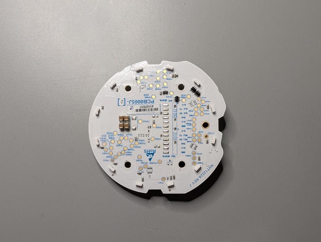
Click to zoom
Application Details
- Equipment Class
- PUB - Part 15 Unlicensed PCS Base Station
- Date of Grant
- May 05, 2026
- Application Purpose
- Original Equipment
- Equipment Note
- SmartCap
- Frequency Range
- 1921.53600000 - 1928.44800000
- Company
- A-Safe HQ LTD
- Country
- United Kingdom
Documents & Files
Document Text
Text extracted from the exhibit documents filed with the FCC. Open a document above to read the original.
Users Manual
User Stories Smart Cap Smart Cap User Stories | 1. Production | 1.1 Pre-Registering Smart Cap 1. Production 1.1 Pre-Registering Smart Cap (Alternative to Install new smart cap) 1. Fully assembled Smart Cap fitted into production jig. 2. Command sent to open registration through production interface. 3. Registration successful indicated by Command response. | 01 SMART CAP REGISTRATION ALERT OPEN REGISTRATION Help REGISTRATION SUCCESSFUL MODEL 03A01YYMMDDXXXXX Help Smart Cap User Stories | 2. Installation | 2.1 Install New Smart Cap 2. Installation 2.1 Install New Smart Cap 1. Holes drilled in floor for post and anchors to be fitted. 2. Post bolted to anchors. All posts must be fitted with Stripe Label facing same direction. 3. Universal Frame fitted to post. 4. Unpack Smart cap from packaging. | 02 Smart Cap User Stories | 2. Installation | 2.1 Install New Smart Cap 5. Smart Cap paired to post by scanning RFID tag on post and QR code on smart cap with App (smart cap in hand). 6. App indicates successful Pairing. 7. Smart Cap installed into frame with quarter turn feature. This automatically powers on the smart cap which will indicate power on using the LED Halo. 8. Smart Cap opens for DECT registration automatically if not already registered. This is indicated on the Halo. Skip to step 10 if already registered. SMART CAP SUCCESSFULLY PAIRED MODEL 03A01YYMMDDXXXXX Help SMART CAP EUROPE 03A01YYMMDDXXXXX 03A01YYMMDDXXXXX | 03 Smart Cap User Stories | 2. Installation | 2.1 Install New Smart Cap 9. Gateway opens for registration based on app navigation. 10. Successful registration indicated on Halo and app. 11. Successful boot up indicated on Halo.12. Smart cap activated (armed) ready for impact (halo lights off). DECT REGISTRATION MODEL REGISTER 03A01YYMMDDXXXXX Help DECT REGISTRATION MODEL 03A01YYMMDDXXXXX Help SUCCESSFULLY REGISTERED | 04 Smart Cap User Stories | 2. Installation | 2.2 Remove Smart Cap 2.2 Remove Smart Cap 1. Smart Cap removed from post using tool to overcome anti tamper latch. 2. Press and hold de-register button until indicated in step 6. 3. Smart cap powers on while de-register button is being pressed and sends a “De-register me” message to the cloud to initiate the cloud life cycle routines. 4. If there is no gateway connection then the smart cap completes a local de-registration. ATTENTION MODEL 03A01YYMMDDXXXXX Help DE REGISTRATION DEREGISTER ME | 05 Smart Cap User Stories | 2. Installation | 2.2 Remove Smart Cap 5. Halo indicates completion. 6. Release De-Registration button to power down smart cap. 7. Replace with new Smart cap as per Install process. | 06 Smart Cap User Stories | 2. Installation | 2.3 Replace Smart Cap 2.3 Replace Smart Cap 1. Follow Remove Smart Cap Process. 2. Follow Install Smart Cap Process SMART CAP EUROPE 03A01YYMMDDXXXXX 03A01YYMMDDXXXXX | 07 Smart Cap User Stories | 2. Installation | 2.4 Change Batteries 3. Drop whole battery cartridge out of smart cap into used battery container. 4. Insert new battery cartridge, pre-loaded with new batteries. 2.4 Change Batteries 1. Smart cap removed from universal frame using tool to overcome anti tamper latch. Smart cap automatically powers down and should not send any impact waveforms. 2. Battery cap removed from bottom of smart cap. | 08 Smart Cap User Stories | 2. Installation | 2.4 Change Batteries 7. Halo indicates normal boot up. Device activated (armed). 5. Replace battery cap.6. Reinsert cap into post. | 09 Smart Cap User Stories | 2. Installation | 2.5 Software Update 2.5 Software Update 3. Smart cap reboots on completion and will run through the normal boot up indication. 1. Smart Caps software update is initiated from the cloud service by an authorized user. 2. Smart Caps do not indicate the software update process on the LED halo. ATTENTION MODEL 03A01YYMMDDXXXXX UPDATE REQUIRED VERSION 1.2.3 UPDATE NOW | 10 Smart Cap User Stories | 3. Inspection | 3.1 Barrier Impact 3. Inspection 3.1 Barrier Impact 1. Vehicle impacts the barrier triggering the smart cap to record an acceleration waveform. 2. Waveform is sent up to the cloud for analysis. 3. Event Response is returned with event classification. Either Alert, Warning, or Null. If the event was not null then the smart cap will indicate with the halo indefinitely. The standard usage model indicates this will be on average 8 hours but this is dependent on regular attention by the customer. If not inspected with 8 hours this could be detrimental to the expected battery life. | 11 Smart Cap User Stories | 3. Inspection | 3.1 Barrier Impact 5. Warehouse inspector arrives at impact site guided by the flashing halo, and location information received via cloud service/app. 6. The inspector scans the RFID tag of the post to verify location. 4A. Notifications will have been sent to the relevant personnel stating that this barrier requires inspection. 4B. The Ping timing when the Halo is flashing should be increased. IMPACT NOTIFICATION Our system has detected an Impact. There could be damage, please inspect this as soon as possible. Time: 13:01 Date: 12/01/2021 Site: A SAFE UK Ltd Zone: Zone B Run: Run 21 Post: 023 IMPACT NOTIFICATION Our system has detected an Impact. There could be damage, please inspect this as soon as possible. Time: 13:01 Date: 12/01/2021 Site: A SAFE UK Ltd Zone: Zone B Run: Run 21 Post: 023 | 12 7. An inspection is completed and the impact event is marked with a resolution status. 8. The Halo indicator turns off. Irrespective of the resolution status. Smart Cap User Stories | 3. Inspection | 3.1 Barrier Impact FULL INSPECTION Is there any damage to X? Yes No | 13 1. If the resolution of an impact event requires removal or replacement of the barrier then this will be indicated and tracked on the cloud service/app. 2. When the maintenance is taking place the smart caps should be removed from the posts thus deactivating them, or a scheduled maintenance should have been created. (See next section). 3.2 Barrier Impact Resolution Smart C…
Text truncated - open the document above for the full version.
Users Manual
LDC-1005-ASF-25022025-V3 130 / 190 Installation Guide SmartCap 02 LDC-1005-ASF-25022025-V3 x1 Sign in to your AccountUsernamePassword Login Remember me Forgotten Password 9:41 03 LDC-1005-ASF-25022025-V3 04 LDC-1005-ASF-25022025-V3 1 2 3 4 6 5 7 8 05 LDC-1005-ASF-25022025-V3 9 10 11 12 14 13 15 16 06 LDC-1005-ASF-25022025-V3 17 18 19 LDC-1005-ASF-25022025-V3 07 Regulatory and compliance information - UK & Europe EU Compliance StatementA-SAFE hereby declares that this wireless device is in compliance with the essential requirements and other relevant provisions of the Directive 2014/53/EU. A copy of the EU Declaration of Conformity for SmartCap is available at www.asafe.com . This device may be operated in all member states of the EU. Observe national and local regulations where the device may be used. This device may be restricted for use, depending on the local network.ImportantChanges or modifications to this product not authorised by A-SAFE could void the electromagnetic compatibility (EMC) and wireless compliance and negate your authority to operate the product.Disposal and Recycling InformationThis symbol on the device, batteries, and/or the packaging, indicates that the device and its batteries should not be disposed of as general waste. SmartCap should not be disposed of as unsorted municipal waste and should be taken to a certified collection point for recycling or proper disposal.Disposal of the device and batteries is subject to WEEE Directive Recast (Directive 2012/19/EU) and Battery Directive (Directive 2006/66/EC). The purpose of separating WEEE and batteries from other waste is to minimise the potential environmental impacts and human health risk of any hazardous substances that may be present.Reduction of Hazardous SubstancesThis device is compliant with RoHS Directive Recast (Directive 2011/65/EU). Batteries are compliant with the Battery Directive (Directive 2006/66/EC). Información sobre cumplimiento de normativa – Europa y Reino Unido. Declaración de cumplimiento de la UE.A-SAFE declara por la presente que este dispositivo inalámbrico cumple los requisitos esenciales y demás disposiciones pertinentes de la Directiva 2014/53/UE. Encontrará una copia de la Declaración de conformidad de la UE para SmartCap en www.asafe.com. Este dispositivo puede utilizarse en todos los estados miembros de la UE. Respete las normativas nacionales y locales donde se utilice el dispositivo. El uso de este dispositivo puede estar restringido dependiendo de la red local.Importante.Los cambios o modificaciones no autorizados por A-SAFE de este producto pueden anular la compatibilidad electromagnética (EMC) y la conformidad inalámbrica y anular su autoridad de uso del producto.Información sobre reciclaje y deshecho.Este símbolo en el dispositivo, pilas y/o embalaje indica que el dispositivo y sus pilas no deben desecharse como residuos generales. SmartCap no debe desecharse como residuo municipal sin clasificar y debe llevarse a un punto de recogida certificado para su reciclaje o adecuada eliminación. La eliminación del dispositivo y las pilas está sujeta a la Directiva refundida RAEE (Directiva 2012/19/UE) y la Directiva sobre pilas (Directiva 2006/66/CE). El objetivo de separar los RAEE y las pilas del resto de residuos es minimizar el impacto medioambiental y el riesgo para la salud humana de cualquier sustancia peligrosa presente.Reducción de sustancias peligrosas.Este dispositivo cumple la Directiva refundida RoHS (Directiva 2011/65/UE). Las pilas cumplen la Directiva sobre pilas y acumuladores (Directiva 2006/66/CE). Risk of explosion if the battery is replaced by an incorrect type. Use only AA Batteries.Failure to observe the safety instructions can result in fire, electric shock and other injuries or damage to the device or other property. The housing is made of plastic with sensitive electronic components and batteries inside. Safety instructions: • Do not pierce, break, crush or cut the device or the battery • Do not expose the device or the battery to an open flame or extremely high temperatures• Do not expose the device or the battery to liquids or extremely low air pressure• Do not drop the device or the battery• Do not try to change or charge the battery in the device• The device or the battery must be recycled or disposed of separately from household waste CAUTION Utiliza únicamente pilas AA. Existe riesgo de explosión si la pila se usa una pila incorrecta. El incumplimiento de las instrucciones de seguridad puede p rovocar un incendio, una descarga eléctrica y/o otras lesiones o daños al dispositivo u otra propiedad. La carcasa está hecha de plástico y contiene componentes electrónicos sensibles y pilas/baterías en el interior. Instrucciones de seguridad: • No perfores, rompas, aplastes ni cortes el dispositivo o la pila o batería• No expongas el dispositivo o la pila o batería a una llama o a temperaturas extremadamente altas• No expongas el dispositivo o la pila o batería a líquidos ni a una presión de aire extremadamente baja• No dejes caer el dispositivo ni la pila o batería• No intentes cambiar o cargar la batería en el dispositivo• El dispositivo o la pila/batería deben reciclarse o eliminarse por separado de los residuos domésticos PRECAUCIÓN 08 LDC-1005-ASF-25022025-V3 Informationen über die gesetzlichen Vorgabenund deren Einhaltung – Großbritannien und Europa EU-KonformitätserklärungA-SAFE erklärt hiermit, dass dieses drahtlose Gerät mit den grundlegenden Anforderungen und anderen relevanten Regelungen der Richtlinie 2014/53/EU übereinstimmt. Eine Kopie der EU-Konformitätserklärung für SmartCap finden Sie unter www.asafe.com. Dieses Gerät darf in allen Mitgliedstaaten der EU betrieben werden. Beachten Sie dabei die nationalen und lokalen Bestimmungen, in denen das Gerät verwendet werden soll. Die Verwendung des Geräts kann je nach lokalem Netzwerk eingeschränkt sein.Wichtig!Änderungen oder Modifikationen an diesem Produkt, die nicht von A-SAFE genehmigt wurden, können …
Text truncated - open the document above for the full version.
Attestation Statements
A-SAFE HQ Ltd Habergham Works Ainley Industrial Estate Elland West Yorkshire HX59JP United Kingdom Federal Communication Commission Authorization and Evaluation Division 7435 Oakland Mills Road Columbia, MD 21046 USA 12/02/2024 Attestation Statement according to 2.911(d)(5)(i) and 2.911(d)(5)(ii) FCC ID: 2AMYT-SC TO WHOM IT MAY CONCERN: Hereby we certify that the equipment for which authorization is sought is not “covered” equipment prohibited from receiving an equipment authorization pursuant to section 2.903 of the FCC rules. Further we certify that, as of the date of the filing of the application A-SAFE HQ Ltd is not identified on the Covered List as an entity producing “covered” equipment. Sincerely, Matthew Wroe _______________ (signature & company stamp) A-SAFE HQ Ltd Habergham Works Ainley Industrial Estate Elland West Yorkshire HX59JP United Kingdom Matthew Wroe +44 (0)1422 344402 [email protected]
Attestation Statements
A-Safe HQ Ltd Habergham Works Ainley Industrial Estate Elland West Yorkshire UK HX5 9JP Federal Communication Commission Authorization and Evaluation Division 7435 Oakland Mills Road Columbia, MD 21046 USA 06/05/2025 Attestation Statement according to 2.911(d)(7) FCC ID: 2AMYT-SC TO WHOM IT MAY CONCERN: We, A-SAFE HQ Ltd designate A-SAFE Inc, to act as U.S. agent for service of process. A-SAFE Inc hereby acknowledges the obligation of the U.S. agent for service of process. Further A-SAFE HQ Ltd accepts to maintain an agent for no less than one year after the grantee has terminated all marketing and importation or the conclusion of any Commission- related proceeding involving the equipment. Sincerely __________________________________ A-SAFE HQ Ltd 0026691337 Habergham Works Ainley Industrial Estate Elland West Yorkshire HX5 9JP UK Matthew Wroe +44 (0)1422 344402 [email protected] __________________________________ A-SAFE Inc 0034885046 400 N Zarfoss Drive York PA17404 Suite A (West) Asad Afzal (717) 659-0619 [email protected] Docusign Envelope ID: 99A6E06A-2B96-46A5-8D75-2B29A8509F9F
Cover Letter(s)
Document Version 1.1 2020-10-30 LONG-TERM CONFIDENTIALITY REQUEST for Certification Service in the USA Federal Communication Commission Equipment Authorization Division, Application Processing Branch 7435 Oakland Mills Road Columbia, MD 21048 TO WHOM IT M AY CONCERN Pursuant to Paragraphs §0.457 and 0.459 of the Commission’s Rules (47 C.F.R.) and Section §552(b)(4) of the Freedom of Information Act, we request Long-Term Confidentiality for the following product: For the product stated above, we request Long-Term Confidentiality for exhibits which contain Block Diagram, Operational Description, Parts List/Tune Up Info, Schematics, SDR Software/Security Info. The above exhibits contain ou r trade secrets and proprietary information that could be of benefit to o ur competitors. This information will not be publicly available. If you have any questions, please feel free to contact us at the address shown below. Sincerely, Company Name: Phone: Company Address: Fax: E-mail: Contact Name: Signature: Signature Date: Check your GC here. Click Grantee Search. FCC I D: Grantee Code Equipment Product Code
External Photos
SmartCap 130 Photos Contents External Photos ................................................................................................................................................................ 2 Isometric Top ................................................................................................................................................................ 2 Isometric Bottom .......................................................................................................................................................... 2 Top ................................................................................................................................................................................ 3 Bottom .......................................................................................................................................................................... 3 Side ................................................................................................................................................................................ 4 Component Photos ........................................................................................................................................................... 5 Lower Housing Top ....................................................................................................................................................... 5 Lower Housing Bottom ................................................................................................................................................. 5 Upper Housing Top ....................................................................................................................................................... 6 Upper Housing Bottom ................................................................................................................................................. 6 Battery Cap Top ............................................................................................................................................................ 7 Battery Cap Bottom ...................................................................................................................................................... 7 Light Guide Top ............................................................................................................................................................. 8 Light Guide Bottom ....................................................................................................................................................... 8 Keypad Top ................................................................................................................................................................... 9 Keypad Bottom ............................................................................................................................................................. 9 PCB Top ....................................................................................................................................................................... 10 PCB Bottom ................................................................................................................................................................. 10 Assembly ......................................................................................................................................................................... 11 External Photos Isometric Top Isometric Bottom Top Bottom Side Component Photos Lower Housing Top Lower Housing Bottom Upper Housing Top Upper Housing Bottom Battery Cap Top Battery Cap Bottom Light Guide Top Light Guide Bottom Keypad Top Keypad Bottom PCB Top PCB Bottom Assembly Start with Lower Housing Add Keypad as shown Add PCB as shown. Add LightGuide over top of PCB, being careful to align LED pockets and screw tab Screw lightguide to lower housing., Add Upper housing ensuring all clips engage. Flip Smart Cap Insert Battery Cartridge ensuring contacts align Screw Battery Cap to lower housing and rotate fully
External Photos
SmartCap 190 Photos Contents External Photos ................................................................................................................................................................ 2 Isometric Top ................................................................................................................................................................ 2 Isometric Bottom .......................................................................................................................................................... 2 Top ................................................................................................................................................................................ 3 Bottom .......................................................................................................................................................................... 3 Side ................................................................................................................................................................................ 4 Component Photos ........................................................................................................................................................... 5 Lower Housing Top ....................................................................................................................................................... 5 Lower Housing Bottom ................................................................................................................................................. 5 Upper Housing Top ....................................................................................................................................................... 6 Upper Housing Bottom ................................................................................................................................................. 6 Battery Cap Top ............................................................................................................................................................ 7 Battery Cap Bottom ...................................................................................................................................................... 7 Light Guide Top ............................................................................................................................................................. 8 Light Guide Bottom ....................................................................................................................................................... 8 Keypad Top ................................................................................................................................................................... 9 Keypad Bottom ............................................................................................................................................................. 9 PCB Top ....................................................................................................................................................................... 10 PCB Bottom ................................................................................................................................................................. 10 Assembly ......................................................................................................................................................................... 11 External Photos Isometric Top Isometric Bottom Top Bottom Side Component Photos Lower Housing Top Lower Housing Bottom Upper Housing Top Upper Housing Bottom Battery Cap Top Battery Cap Bottom Light Guide Top Light Guide Bottom Keypad Top Keypad Bottom PCB Top PCB Bottom Assembly Start with Lower Housing Add Keypad as shown Add PCB as shown. Add LightGuide over top of PCB, being careful to align LED pockets and screw tab Screw lightguide to lower housing., Add Upper housing ensuring all clips engage. Flip Smart Cap Insert Battery Cartridge ensuring contacts align Screw Battery Cap to lower housing and rotate fully
External Photos
Annex A102 - Photographs No.1-7110/23-01-03_TR1-A102-R1 March 13, 2024 DescriptionExternal photographs of EUT This document is electronically signed and valid without handwritten signature. Public keys for verification of the electronic signatures can be requested at the testing laboratory. Authorized Alexander Becker Lab Manager Radio Labs cetecom advanced GmbH Untertürkheimer Str. 6-10, 66117 Saarbrücken Document No. 1-7110/23-01-03_TR1-A102-R1 Release 1 - Page 1 of 4 Photo 1 Photo 2 cetecom advanced GmbH Untertürkheimer Str. 6-10, 66117 Saarbrücken Document No. 1-7110/23-01-03_TR1-A102-R1 Release 1 - Page 2 of 4 Photo 3 Photo 4 cetecom advanced GmbH Untertürkheimer Str. 6-10, 66117 Saarbrücken Document No. 1-7110/23-01-03_TR1-A102-R1 Release 1 - Page 3 of 4 Photo 5 - END OF DOCUMENT - cetecom advanced GmbH Untertürkheimer Str. 6-10, 66117 Saarbrücken Document No. 1-7110/23-01-03_TR1-A102-R1 Release 1 - Page 4 of 4
ID Label/Location Info
Product Labelling SmartCap 130 North American variants will be labelled with this label: SmartCap 190 North American variants will be labelled with this label: SmartCap 130 European variants will be labelled with this label SmartCap 190 European variants will be labelled with this label Note that these labels show certification marks that have not yet been approved. No marks will be shown on the label of production parts if the certification has not been granted. Instead, a blank space will be left. The Label size is 60 x 20mm. All text is font Arial size 5pt or greater. All certification icons are 5mm tall and width matches original image ratio. The QR code encodes the device serial. Size Height 20mm, Width 60mm (up to 180mm) Material Polyester Adhesive type Permanent Label Colour Silver Matt Printing Type Thermal Transfer (indelible) Printing Colour Black Printer Compatibility 600dpi TSC TX600 Mounted Material PC-ABS Temperature Range -40°C to +85°C Humidity Range 20% – 95% Label Stock CILS TP6-TSSPET(HSE)-0.5-3C or equivalent Ribbon Stock CILS TTR-ARA1-110/300 or equivalent Label is affixed to the “stalk of the smart cap in a recessed pocket. The label is only visible when the SmartCap is not fitted to a Barrier post.
Internal Photos
Annex A101 - Photographs No.1-7110/23-01-03_TR1-A101-R1 March 13, 2024 DescriptionInternal photographs of EUT This document is electronically signed and valid without handwritten signature. Public keys for verification of the electronic signatures can be requested at the testing laboratory. Authorized Alexander Becker Lab Manager Radio Labs cetecom advanced GmbH Untertürkheimer Str. 6-10, 66117 Saarbrücken Document No. 1-7110/23-01-03_TR1-A101-R1 Release 1 - Page 1 of 3 Photo 1 Photo 2 cetecom advanced GmbH Untertürkheimer Str. 6-10, 66117 Saarbrücken Document No. 1-7110/23-01-03_TR1-A101-R1 Release 1 - Page 2 of 3 Photo 3 Photo 4 - END OF DOCUMENT - cetecom advanced GmbH Untertürkheimer Str. 6-10, 66117 Saarbrücken Document No. 1-7110/23-01-03_TR1-A101-R1 Release 1 - Page 3 of 3
RF Exposure Info
Test Report No. 1-7110-23-01-11_TR1-R01 April 30. 2026 ApplicantA-Safe HQ Ltd. ProductBarrier Impact Sensor ModelSmartCap 130 NA Tested TechnologyDECT Test StandardFCC 47 CFR Part 2 VerdictTEST EXEMPTION FULFILLED The test results apply only to the equipment specified in this document. This test report is electronically signed and valid without handwritten signature. Public keys for verification of the electronic signatures can be requested at the testing laboratory. Alexander Hnatovskiy Coordinator Area Regulatory Services Radio authorized by Eric Tuettmann Testing Manager Regulatory Services Radio created by cetecom advanced GmbH Untertuerkheimer Str. 6-10, 66117 Saarbruecken Document No. 1-7110-23-01-11_TR1-R01 Page 1 of 11 Table of Contents 1.Disclaimer....................................................................................................................................................3 2.Document history..........................................................................................................................................4 2.1.Current release.................................................................................................................................................................................4 2.2.Previous releases.............................................................................................................................................................................4 3.Test laboratory..............................................................................................................................................5 3.1.Contact information.........................................................................................................................................................................5 3.2.Involved test locations......................................................................................................................................................................5 3.3.Subcontracted laboratories...............................................................................................................................................................5 3.4.Laboratory listings and recognitions.................................................................................................................................................5 4.Client information.........................................................................................................................................6 4.1.Applicant..........................................................................................................................................................................................6 4.2.Manufacturer....................................................................................................................................................................................6 5.Test sample information...............................................................................................................................7 5.1.General Information.........................................................................................................................................................................7 5.1.1.General Data of Main EUT as Declared by Applicant...................................................................................................................7 6.Measurement details...................................................................…
Text truncated - open the document above for the full version.
Contact Information
Applicant
Matthew Wroe(Mr)
[email protected]Fax: +44 (0)14422323533
Technical Contact
A-Safe IncAsad Afzal
400N Zarfoss Drive Suite A (West) · York, Pennsylvania, 17404 · United States
Test Firm
cetecom advanced GmbHGerald Schmidt
[email protected]Fax: 49-681-598-8775
Technical Specifications
| # | Rule Parts | Frequency Range | Power Output | Tolerance |
|---|---|---|---|---|
| 1 | 15D | 1.92 GHz - 1.93 GHz | 43.00 mW | 2.1600000000ppm |