Text extracted from the exhibit documents filed with the FCC. Open a document above to read the original.
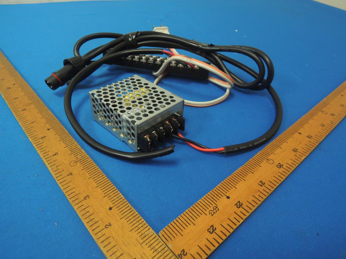
Product manual Product name: 2.4G Zigbee Model: PT-001-A1 A. Explanation: This temperature monitoring product can be applied to the temperature monitoring of various ice water hosts In addition, the temperature can be transmitted in real time through wireless, and the temperature can be returned to the cloud back-end database for temperature curve analysis. After the analysis, determine whether the ice water host is working properly! B. Power supply precautions: 1. The positive and negative polarities of the power supply have been locked to the terminals before leaving the factory (Figure 1). Or arbitrarily reinstall the power supply. If the product is damaged, please be responsible for the maintenance costs! 2. It must be noted that the external voltage input cannot be greater than DC24V, and it must not be smaller than DC15V. C. Rated voltage and current 1. You can use any type of DC power supply commercially available, but please refer to the voltage Only between + 15VDC-+ 24VDC! 2. The current must be greater than 0.35A D. The RF isolation wire and the RF antenna bracket are installed and calibrated before leaving the factory. Do not change or replace them at will! E. The temperature detection sensor is also calibrated by the laboratory before leaving the factory. Do not replace it randomly. If there is any problem Call Huakai Optoelectronics. F. If you have any technical problems, please call Huakai Optoelectronics Communication Company. G. RF frequency used: 2405MHZ ~ 2480MHZ Maximum current consumption DC15V / 0.2A H. In the end, please don't remove the cover of the wireless thermometer (Figure 2) without any need to avoid any dust, etc. Avoid damage! I. General equipment (Articles 12 and 14 of the Measures for the Administration of Low Power Radio Wave Radiated Motors) -Low-power RF motors that have passed the type approval are not allowed to change the frequency, increase the power, or change the characteristics and functions of the original design without permission. --- The use of low-power RF motors must not affect the safety of aviation and interfere with legal communications: When interference is found, it should be stopped immediately and improved to no interference before continued use. The legal communication in the preceding paragraph refers to radio communication low-power radio frequency motors operating in accordance with the provisions of the Telecommunications Law. C.Federal Communication Commission Interference Statement This equipment has been tested and found to comply with the limits for a Class B digital device, pursuant to Part 15 of the FCC Rules. These limits are designed to provide reasonable protection against harmful interference in a residential installation. This equipment generates, uses, and can radiate radio frequency energy and, if not installed and used in accordance with the instructions, may cause harmful interference to radio communications. However, there is no guarantee that interference will not occur in a particular installation. If this equipment does cause harmful interference to radio or television reception, which can be determined by turning the equipment off and on, the user is encouraged to try to correct the interference by one or more of the following measures: • Reorient or relocate the receiving antenna. • Increase the separation between the equipment and receiver. • Connect the equipment into an outlet on a circuit different from that to which the receiver is connected. • Consult the dealer or an experienced radio/TV technician for help. FCC Caution (15.19 statement) This device complies with Part 15 of the FCC Rules. Operation is subject to the following two conditions: (1) This device may not cause harmful interference, and (2) this device must accept any interference received, including interference that may cause undesired operation. Non-modification Statement: Changes or modifications not expressly approved by the party responsible for compliance could void the user's authority to operate the equipment. FCC Radiation Exposure Statement: This equipment complies with FCC radiation exposure limits set forth for an uncontrolled environment. This equipment should be installed and operated with minimum distance 20cm between the radiator & your body. Professional Installation Instructions This product is designed for specific application and needs to be installed by a qualified personal who has RF and related rule knowledge. The general user shall not attempt to install or change the setting. Installation Notes The installation method of PT-001-A1 is as follows 1. Generally, the ice water pipe or the ice water host will open the holes first. 2. Then insert PT-001-A1 into the hole. The front end of PT-001-A1 is a platinum high-precision sensor rod with a length of about 10-15 cm(Figure III).. Insert the sensor rod to the bottom of the hole. There must be no Gap, which will cause measurement errors 3. If the hole is less than 10-15 cm, the sensor rod must be cut to make it optimally installed. (Figure IV). 4. After installation, plug in the power supply and start measuring temperature Figure I Figure II Figure III Figure IV
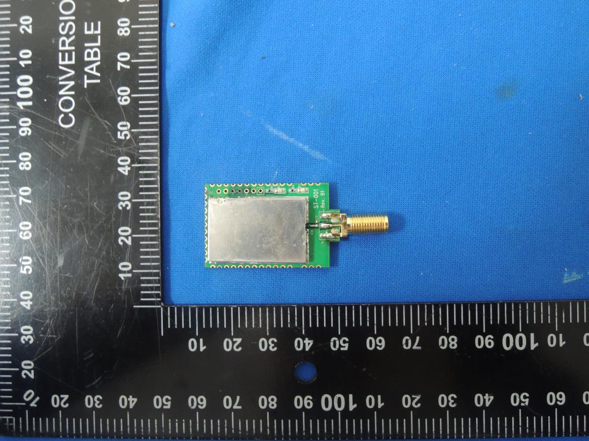
CERPASS TECHNOLOGY CORP. Report No.: 1911157 Cerpass Technology Corp. Issued Date : Jan. 08, 2020 Page No. : 1 of 4 Photographs of EUT Antenna position CERPASS TECHNOLOGY CORP. Report No.: 1911157 Cerpass Technology Corp. Issued Date : Jan. 08, 2020 Page No. : 2 of 4 CERPASS TECHNOLOGY CORP. Report No.: 1911157 Cerpass Technology Corp. Issued Date : Jan. 08, 2020 Page No. : 3 of 4 CERPASS TECHNOLOGY CORP. Report No.: 1911157 Cerpass Technology Corp. Issued Date : Jan. 08, 2020 Page No. : 4 of 4
Label & Location
CERPASS TECHNOLOGY CORP. Report No.: 1911157 Cerpass Technology Corp. Issued Date : Jan. 08, 2020 Page No. : 1 of 3 Photographs of EUT CERPASS TECHNOLOGY CORP. Report No.: 1911157 Cerpass Technology Corp. Issued Date : Jan. 08, 2020 Page No. : 2 of 3 Antenna Connect RF Chip CERPASS TECHNOLOGY CORP. Report No.: 1911157 Cerpass Technology Corp. Issued Date : Jan. 08, 2020 Page No. : 3 of 3
CERPASS TECHNOLOGY CORP. Report No.: TEFQ1911157 Cerpass Technology Corp. Issued Date : Jan. 08, 2020 T-FD-506-0 Ver 1.2 Page No. : 39 of 41 FCC ID. : 2AN3JPT001-A1 12. Radio Frequency Exposure 12.1 Applicable Standards The measurements shown in this test report were made in accordance with the procedures given in FCC Part 2 (Section 2.1091) 12.2 EUT Specification Frequency band (Operating) WLAN: 2412MHz ~ 2462MHz WLAN: 5150MHz ~ 5250MHz WLAN: 5250MHz ~ 5350MHz WLAN: 5470MHz ~ 5725MHz WLAN: 5725MHz ~ 5850MHz Zigbee: 2405MHz ~ 2475MHz Device category Portable (<20cm separation) Mobile (>20cm separation) Exposure classification Occupational/Controlled exposure (S = 5mW/cm 2 ) General Population/Uncontrolled exposure (S=1mW/cm 2 ) Antenna diversity Single antenna Multiple antennas Tx diversity Rx diversity Tx/Rx diversity Evaluation applied MPE Evaluation* SAR Evaluation N/A Remark: 1. The maximum conducted output power is 18.96dBm (78.705mW) at 2405MHz (with 2dBi antenna gain.) 2. DTS device is not subject to routine RF evaluation; MPE estimate is used to justify the compliance. 3. For mobile or fixed location transmitters, no SAR consideration applied. The maximum power density is 1.0 mW/cm 2 even if the calculation indicates that the power density would be larger. CERPASS TECHNOLOGY CORP. Report No.: TEFQ1911157 Cerpass Technology Corp. Issued Date : Jan. 08, 2020 T-FD-506-0 Ver 1.2 Page No. : 40 of 41 FCC ID. : 2AN3JPT001-A1 12.3 Test Results No non-compliance noted. 12.4 Calculation Given d GP E 30 & 3770 2 E S Where E = Field strength in Volts / meter P = Power in Watts G = Numeric antenna gain d = Distance in meters S = Power density in milliwatts / square centimeter Combining equations and re-arranging the terms to express the distance as a function of the remaining variables yields: 2 3770 30 d GP S Changing to units of mW and cm, using: P (mW) = P (W) / 1000 and d (cm) = d(m) / 100 Yields 2 2 0796.0 100/3770 1000/30 d GP d GP S Equation 1 Where d = Distance in cm P = Power in mW G = Numeric antenna gain S = Power density in mW / cm 2 CERPASS TECHNOLOGY CORP. Report No.: TEFQ1911157 Cerpass Technology Corp. Issued Date : Jan. 08, 2020 T-FD-506-0 Ver 1.2 Page No. : 41 of 41 FCC ID. : 2AN3JPT001-A1 12.5 Maximum Permissible Exposure Channel Frequency (MHz) Max. Conducted output power (dBm) Max. Tune up power (dBm) Antenna Gain (dBi) Distance (cm) Power Density (mW/cm 2 ) Limit (mW/cm 2 ) 2405-2475 18.96 20.96 2 20 0.039 1
CERPASS TECHNOLOGY CORP. Report No.: TEFQ1911157 Cerpass Technology Corp. Issued Date : Jan. 08, 2020 T-FD-506-0 Ver 1.2 Page No. : 1 of 41 FCC ID. : 2AN3JPT001-A1 FCC RADIO TEST REPORT Applicant : EverComm Opto Ltd. Address : 9F-5,No.880, Zhongzheng Rd., Zhonghe Dist.,New Taipei City 23586, Taiwan Equipment : 2.4G ZIGBEE wireless digital platinum resistance thermometer Model No. : PT-001-A1 Trade Name : FCC ID : 2AN3JPT001-A1 I HEREBY CERTIFY THAT : The sample was received on Nov. 21, 2019 and the testing was completed on Dec. 13, 2019 at Cerpass Technology Corp. The test result refers exclusively to the test presented test model / sample. Without written approval of Cerpass Technology Corp., the test report shall not be reproduced except in full. Approved by: Mark Liao / Supervisor Laboratory Accreditation: Cerpass Technology Corporation Test Laboratory CERPASS TECHNOLOGY CORP. Report No.: TEFQ1911157 Cerpass Technology Corp. Issued Date : Jan. 08, 2020 T-FD-506-0 Ver 1.2 Page No. : 2 of 41 FCC ID. : 2AN3JPT001-A1 Contents 1. Summary of Test Procedure and Test Results ................................................................................. 5 1.1 Applicable Standards ................................................................................................................. 5 2. Test Configuration of Equipment under Test ................................................................................... 6 2.1 Feature of Equipment under Test ............................................................................................... 6 2.2 Carrier Frequency of Channels .................................................................................................. 6 2.3 Test Mode and Test Software ..................................................................................................... 6 2.4 Description of Test System ......................................................................................................... 6 2.5 General Information of Test ........................................................................................................ 7 2.6 Measurement Uncertainty .......................................................................................................... 7 3. Test Equipment and Ancillaries Used for Tests ............................................................................... 8 4. Antenna Requirements ..................................................................................................................... 10 4.1 Standard Applicable ................................................................................................................. 10 4.2 Antenna Construction and Directional Gain ............................................................................. 10 5. Test of AC Power Line Conducted Emission ................................................................................. 11 5.1 Test Limit .................................................................................................................................. 11 5.2 Test Procedures ....................................................................................................................... 11 5.3 Typical Test Setup .................................................................................................................... 12 5.4 Test Result and Data ................................................................................................................ 13 5.5 Test Photographs ..................................................................................................................... 15 6. Test of Spurious Emission (Radiated) ............................................................................................ 16 6.1 Test Limit .................................................................................................................................. 16 6.2 Test Procedures ....................................................................................................................... 16 6.3 Typical Test Setup .................................................................................................................... 17 6.4 Test Result and Data (9kHz ~ 30MHz) ..................................................................................... 18 6.5 Test Result and Data (30MHz ~ 1GHz) .................................................................................... 18 6.6 Test Result and Data (1GHz ~ 25GHz) .................................................................................... 20 6.7 Restricted Bands of Operation ................................................................................................. 26 6.8 Test Photographs (30MHz ~ 1GHz) ......................................................................................... 27 6.9 Test Photographs (1GHz ~ 25GHz) ......................................................................................... 28 7. Test of Spurious Emission (Conducted) ......................................................................................... 29 7.1 Test Limit .................................................................................................................................. 29 7.2 Test Procedure ......................................................................................................................... 29 7.3 Test Setup Layout .................................................................................................................... 29 7.4 Test Result and Data ................................................................................................................ 29 8. On Time, Duty Cycle and Measurement methods ......................................................................... 32 8.1 Test Limit .................................................................................................................................. 32 8.2 Test Proc…
Text truncated - open the document above for the full version.
CERPASS TECHNOLOGY CORP. Report No.: TEFQ1911157 Cerpass Technology Corp. Issued Date : Jan. 08, 2020 T-FD-506-0 Ver 1.2 Page No. : 15 of 41 FCC ID. : 2AN3JPT001-A1 5.5 Test Photographs Front View Rear View CERPASS TECHNOLOGY CORP. Report No.: TEFQ1911157 Cerpass Technology Corp. Issued Date : Jan. 08, 2020 T-FD-506-0 Ver 1.2 Page No. : 27 of 41 FCC ID. : 2AN3JPT001-A1 6.8 Test Photographs (30MHz ~ 1GHz) Front View Rear View CERPASS TECHNOLOGY CORP. Report No.: TEFQ1911157 Cerpass Technology Corp. Issued Date : Jan. 08, 2020 T-FD-506-0 Ver 1.2 Page No. : 28 of 41 FCC ID. : 2AN3JPT001-A1 6.9 Test Photographs (1GHz ~ 25GHz) Front View Rear View
| # | Rule Parts | Frequency Range | Power Output |
|---|---|---|---|
| 1 | 15C | 2.40 GHz - 2.48 GHz | 79.00 mW |

CC2538 Zigbee wireless module
Equipment Class
DTS - Digital Transmission System