2AN3WM5NANOC6M5NanoC6
M5Stack Technology Co.,Ltd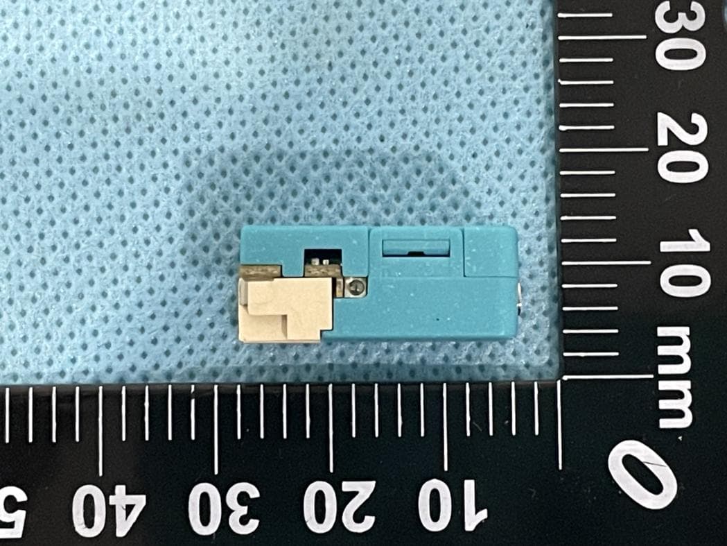
Click to zoom
Application Details
- Equipment Class
- DTS - Digital Transmission System
- Date of Grant
- Mar 12, 2024
- Application Purpose
- Original Equipment
- Date of Application
- Mar 12, 2024
- Equipment Note
- M5NanoC6
- Frequency Range
- 2405.00000000 - 2480.00000000
- Company
- M5Stack Technology Co.,Ltd
- Country
- China
Documents & Files
Document Text
Text extracted from the exhibit documents filed with the FCC. Open a document above to read the original.
Users Manual
M5STACK NanoC6 2023 CONTENTS 2. 3. SPECIFICATIONS.......................................................................................................4 QUICK START.............................................................................................................5 1.1. 3.1. 3.2. 3.3. 3.4. ESP32-C6 ...........................................................................................................3 1.OUTLINE .....................................................................................................................3 ARDUINO IED.....................................................................................................5 BLUETOOTH SERIAL.........................................................................................5 WIFI SCANNING.................................................................................................7 ZIGBEE...............................................................................................................8 1. OUTLINE M5NanoC6 is a miniature, low-power IoT development board within the M5Stack development kit series. Powered by the ESP32-C6 MCU, it boasts advanced wireless communication support, including Wi-Fi 6 and Zigbee, facilitating seamless control of infrared IoT devices through its built-in infrared transmitter. The onboard ceramic antenna ensures a stable wireless communication connection. Additionally, the device features programmable RGB LEDs, adding a personalized visual touch to projects. The inclusion of Grove interfaces allows M5NanoC6 to flexibly expand with various M5 devices, supporting the connection of different device types through protocols such as UART and I2C. This provides developers with abundant hardware expansion possibilities. Suitable for applications in smart homes, industrial automation, health monitoring, and IoT devices, M5NanoC6 delivers a comprehensive development solution for innovative projects. 1.1. ESP32-C6 Communication Capabilities:1. Supports 2.4 GHz Wi-Fi 6 (802.11 ax): Provides high-speed and efficient Wi-Fi communication. Bluetooth® 5 (LE): Incorporates Bluetooth 5.0 technology for extended wireless coverage and faster data transmission. Zigbee and Thread (802.15.4): Supports Zigbee and Thread communication protocols, offering flexible connectivity for IoT applications. Processor and Performance:2. RISC-V 32-bit single-core processor: Delivers a highly flexible and scalable processor architecture. Up to 160 MHz clock frequency: Ensures the device has fast and efficient data processing capabilities. Industry-leading low-power and RF performance: Achieves a leading position in both power consumption and RF performance. Memory:3. Built-in 320 KB ROM: Used for storing firmware or program code. 512 KB SRAM: Utilized for runtime data storage. 16 KB low-power SRAM: Specifically designed for low-power operations. Supports external Flash: Can extend the storage space for program code through an external memory. GPIO Pins and Programmable Interfaces:4. Supports SPI, UART, I2C, I2S, RMT, TWAI, and PWM: Multiple communication interfaces, enhancing flexibility for data exchange with other devices. 2. SPECIFICATIONS Communication mode Communication Protocol Input voltage Antenna type Specification Onboard ceramic antenna 5V 2.4 GHz Wi-Fi 6 (802.11 ax)、Zigbee And Thread (802.15.4)And other mainstream communication methods Support SPI、UART、I2C、I2S、RMT、TWAI And PWM Board infrared transmitter, programmable onboard control buttons ESP32-C6FH4@RISC-V 32-bit single-core processor 160 MHZ, 320 KB ROM, 512 KB SRAM, 16 KB low-power SRAM, supports external flash Parameter WS2812-2020 Programmable RGB Other peripherals Operating temperature 0-40°C MCU FCC Caution: Any changes or modifications not expressly approved by the party responsible for compliance could void the user's authority to operate the equipment. This device complies with part 15 of the FCC Rules. Operation is subject to the following two conditions: (1) This device may not cause harmful interference, and (2) this device must accept any interference received, including interference that may cause undesired operation. IMPORTANT NOTE: Note: This equipment has been tested and found to comply with the limits for a Class B digital device, pursuant to part 15 of the FCC Rules. These limits are designed to provide reasonable protection against harmful interference in a residential installation. This equipment generates, uses and can radiate radio frequency energy and, if not installed and used in accordance with the instructions, may cause harmful interference to radio communications. However, there is no guarantee that interference will not occur in a particular installation. If this equipment does cause harmful interference to radio or television reception, which can be determined by turning the equipment off and on, the user is encouraged to try to correct the interference by one or more of the following measures: • Reorient or relocate the receiving antenna. • Increase the separation between the equipment and receiver. • Connect the equipment into an outlet on a circuit different from that to which the receiver is connected. • Consult the dealer or an experienced radio/TV technician for help. FCC Radiation Exposure Statement : This equipment complies with FCC radiation exposure limits set forth for an uncontrolled environment. The SAR was tested for the device in thebody worn mode with 5mm distance. And it can meet the SAR limit of FCC. 3. QUICK START To access the Arduino official website (https://www.arduino.cc/en/Main/Software) and download the installation package for your operating system, follow these steps: Open the Arduino IDE and navigate to File -> Preferences -> Settings.1. Copy the following M5Stack Boards Manager URL and paste it into "Additional Boards Manager URLs": https://m5stack.oss-cn- shenzhen.aliyuncs.com/resource/arduino/package_m5stack_index.json 2. Go to: Tools -> Board: -> Boards Manager...3. Search for M…
Text truncated - open the document above for the full version.
Cover Letter(s)
M5Stack Technology Co.,Ltd Address: 5F,Tangwei Stock Commercial Building, Youli Road, Bao'an District, Shenzhen, Guangdong,China Tel.: 13509230623 E-Mail: [email protected] Date: 2024-02-21 FEDERAL COMMUNICATIONS COMMISSION Authorization and Evaluation Division 7435 Oakland Mills Road Columbia, MD 21046 Dear Sir/Madam, We, M5Stack Technology Co.,Ltd hereby authorize World Alliance Testing & Certification(Shenzhen) Co., Ltd. to act as a laboratory for testing and test report generation for the following project(s): (Product description: M5NanoC6, model name: NanoC6, FCC ID: 2AN3WM5NANOC6) For use in America this chip only support/enable BLE 1M/2M : 2402-2480MHz, Zigbee & Thread: 2405-2480MHz, 2.4G Wi-Fi: 2412-2472MHz: 802.11b/g/n20 & 802.11ax20(full RU), 2422-2462MHz: 802.11 n40, other functions have been shielded by the manufacturer using the software and the end user cannot activate. Sincerely, Signature: Contact person: Jimmy Lai Title: CEO
External Photos
Report No.: RWAO202400028 Page 1 of 3 EUT EXTERNAL PHOTOGRAPHS Report No.: RWAO202400028 Page 2 of 3 Report No.: RWAO202400028 Page 3 of 3
Internal Photos
Report No.: RWAO202400028 Page 1 of 3 EUT INTERNAL PHOTOGRAPHS Report No.: RWAO202400028 Page 2 of 3 Report No.: RWAO202400028 Page 3 of 3 ANT
RF Exposure Info
SAR TEST REPORT Applicant: M5Stack Technology Co., Ltd Address: 5F, Tangwei Stock Commercial Building Youli Road, Bao’an District, Shenzhen,Guangdong,China FCC ID: 2AN3WM5NANOC6 Product Name: M5NanoC6 Model Number: NanoC6 Standard(s): 47 CFR Part 2(2.1093) The above devicehas been tested and found compliant with the requirement of the relativestandards by China Certification ICT Co., Ltd (Dongguan) Report Number: CR231274561-SA Date Of Issue: 2024-02-27 Reviewed By: Ken Zong Title: SAR Project Engineer Approved By : Karl Gong Title: SAR Engineer Test Laboratory: China Certification ICT Co., Ltd (Dongguan) No. 113, Pingkang Road, Dalang Town, Dongguan, Guangdong, China Tel: +86-769-82016888 China Certification ICT Co., Ltd (Dongguan) Report No.: CR231274561-SA Page 2 of 37 SAR TEST RESULTSSUMMARY Operation Frequency Bands Highest Reported 1g SAR (W/kg) Limits (W/kg) Head SAR Body SAR (Gap 5mm) WLAN 2.4G NA 0.07 1.6 BLE NA 0.04 ZigBee/Thread NA 0.01 Maximum Simultaneous Transmission SAR Items Head SAR Body SAR (Gap 5mm) Hotspot (Gap 5mm) Limits Sum SAR(W/kg) NA NA NA 1.6 SPLSR NA NA NA 0.04 EUT Received Date: 2023/12/18 Tested Date: 2024/01/29 Tested Result: Pass China Certification ICT Co., Ltd (Dongguan) Report No.: CR231274561-SA Page 3 of 37 Test Facility The Test site used by China Certification ICT Co., Ltd (Dongguan) to collect test data is located on the No. 113, Pingkang Road, Dalang Town, Dongguan, Guangdong, China. The lab has been recognized as the FCC accredited lab under the KDB 974614 D01 and is listed in the FCC Public Access Link (PAL) database, FCC Registration No. : 442868, the FCC Designation No. : CN1314. Declarations China Certification ICT Co., Ltd (Dongguan) is not responsible for the authenticity of any test data provided by the applicant. Data included from the applicant that may affect test results are marked with a triangle symbol “▲”. Customer model name, addresses, names, trademarks etc. are not considered data. Unless otherwise stated the results shown in this test report refer only to the sample(s) tested. This report cannot be reproduced except in full, without prior written approval of the Company. This report is valid only with a valid digital signature. The digital signature may be available only under the Adobe software above version 7.0. This report may contain data that are not covered by the accreditation scope and shall be marked with an asterisk “★”. China Certification ICT Co., Ltd (Dongguan) Report No.: CR231274561-SA Page 4 of 37 CONTENTS DOCUMENT REVISION HISTORY .......................................................................................... 6 1. GENERAL INFORMATION .................................................................................................... 7 1.1 PRODUCT DESCRIPTION FOR DEVICE UNDER TEST (EUT) ............................................................... 7 1.2TEST SPECIFICATION, METHODS AND PROCEDURES ......................................................................... 8 1.3 SAR LIMITS .......................................................................................................................................... 9 1.4 FACILITIES ...................................................................................................................................... 10 2. SAR MEASUREMENTSYSTEM ........................................................................................... 11 3. EQUIPMENT LIST AND CALIBRATION .......................................................................... 18 3.1 EQUIPMENTS LIST & CALIBRATION INFORMATION ....................................................................... 18 4. SAR MEASUREMENT SYSTEM VERIFICATION ........................................................... 19 4.1 LIQUID VERIFICATION ...................................................................................................................... 19 4.2 SYSTEM ACCURACY VERIFICATION ................................................................................................. 20 4.3 SAR SYSTEM VALIDATION DATA ............................................................................................. 21 5. EUT TEST STRATEGY AND METHODOLOGY .............................................................. 22 5.1 SIMPLE DONGLE PROCEDURES ............................................................................................... 22 TEST DISTANCE FOR SAR EVALUATION ................................................................................................ 22 5.6 SAR EVALUATION PROCEDURE ....................................................................................................... 23 6. CONDUCTED OUTPUT POWER MEASUREMENT ........................................................ 24 6.1 TEST PROCEDURE .............................................................................................................................. 24 6.3 MAXIMUM TARGET OUTPUT POWER ............................................................................................... 24 6.4 TEST RESULTS: .................................................................................................................................. 25 7. Standalone SAR test exclusion considerations ....................................................................... 27 7.2STANDALONE SAR TEST EXCLUSION CONSIDERATIONS .................................................................. 27 8. SAR MEASUREMENT RESULTS ........................................................................................ 28 8.1 SAR TEST DATA ................................................................................................................................ 28 9. Measurement Variability ......................................................................................................... 31 10. SAR SIMULTANEOUS TRANSMISSION DESCRIPTION ............................................ 32 11. SAR Plots .................................…
Text truncated - open the document above for the full version.
RF Exposure Info
APPENDIX C CALIBRATION CERTIFICATES DIPOLE CALIBRATION CERTIFICATES
RF Exposure Info
China Certification ICT Co., Ltd (Dongguan) Report No.: CR231274561-SA Page 1 of 15 Test Plot 1# DUT: NanoC6; Type: M5NanoC6; Serial: 2FDS-1; Communication System: UID 0, 2.4G DTS (0); Frequency: 2442 MHz;Duty Cycle: 1:1 Medium parameters used (interpolated): f = 2442 MHz; σ = 1.778 S/m; ε r = 40.192; ρ = 1000 kg/m 3 Phantom section: Flat Section DASY5 Configuration: Probe: ES3DV3 - SN3157; ConvF(4.74, 4.74, 4.74) @ 2442 MHz; Calibrated: 2023/4/10 Sensor-Surface: 3mm (Mechanical Surface Detection) Electronics: DAE4 Sn1493; Calibrated: 2023/3/17 Phantom: Twin SAM; Type: Twin SAM V5.0; Serial: TP:1470 Measurement SW: DASY52, Version 52.8 (7); SEMCAD X Version 14.6.12 (7164) Horizontal-Up/WLAN 802.11b Mid/Area Scan (11x11x1): Measurement grid: dx=10mm, dy=10mm Maximum value of SAR (measured) = 0.0370 W/kg Horizontal-Up/WLAN 802.11b Mid/Zoom Scan (7x7x7)/Cube 0: Measurement grid: dx=5mm, dy=5mm, dz=5mm Reference Value = 1.472 V/m; Power Drift = 0.00 dB Peak SAR (extrapolated) = 0.0360 W/kg SAR(1 g) = 0.023 W/kg; SAR(10 g) = 0.014 W/kg Maximum value of SAR (measured) = 0.0317 W/kg 0 dB = 0.0317 W/kg = -14.99 dBW/kg China Certification ICT Co., Ltd (Dongguan) Report No.: CR231274561-SA Page 2 of 15 Test Plot 2# DUT: NanoC6; Type: M5NanoC6; Serial: 2FDS-1; Communication System: UID 0, 2.4G DTS (0); Frequency: 2442 MHz;Duty Cycle: 1:1 Medium parameters used (interpolated): f = 2442 MHz; σ = 1.778 S/m; ε r = 40.192; ρ = 1000 kg/m 3 Phantom section: Flat Section DASY5 Configuration: Probe: ES3DV3 - SN3157; ConvF(4.74, 4.74, 4.74) @ 2442 MHz; Calibrated: 2023/4/10 Sensor-Surface: 3mm (Mechanical Surface Detection) Electronics: DAE4 Sn1493; Calibrated: 2023/3/17 Phantom: Twin SAM; Type: Twin SAM V5.0; Serial: TP:1470 Measurement SW: DASY52, Version 52.8 (7); SEMCAD X Version 14.6.12 (7164) Horizontal-Down/WLAN 802.11b Mid/Area Scan (11x11x1): Measurement grid: dx=10mm, dy=10mm Maximum value of SAR (measured) = 0.0386 W/kg Horizontal-Down/WLAN 802.11b Mid/Zoom Scan (7x7x7)/Cube 0: Measurement grid: dx=5mm, dy=5mm, dz=5mm Reference Value = 1.785 V/m; Power Drift = 0.06 dB Peak SAR (extrapolated) = 0.0340 W/kg SAR(1 g) = 0.016 W/kg; SAR(10 g) = 0.010 W/kg Maximum value of SAR (measured) = 0.0242 W/kg 0 dB = 0.0242 W/kg = -16.16 dBW/kg China Certification ICT Co., Ltd (Dongguan) Report No.: CR231274561-SA Page 3 of 15 Test Plot 3# DUT: NanoC6; Type: M5NanoC6; Serial: 2FDS-1; Communication System: UID 0, 2.4G DTS (0); Frequency: 2442 MHz;Duty Cycle: 1:1 Medium parameters used (interpolated): f = 2442 MHz; σ = 1.778 S/m; ε r = 40.192; ρ = 1000 kg/m 3 Phantom section: Flat Section DASY5 Configuration: Probe: ES3DV3 - SN3157; ConvF(4.74, 4.74, 4.74) @ 2442 MHz; Calibrated: 2023/4/10 Sensor-Surface: 3mm (Mechanical Surface Detection) Electronics: DAE4 Sn1493; Calibrated: 2023/3/17 Phantom: Twin SAM; Type: Twin SAM V5.0; Serial: TP:1470 Measurement SW: DASY52, Version 52.8 (7); SEMCAD X Version 14.6.12 (7164) Vertical-Front/WLAN 802.11b Mid/Area Scan (11x11x1): Measurement grid: dx=10mm, dy=10mm Maximum value of SAR (measured) = 0.101 W/kg Vertical-Front/WLAN 802.11b Mid/Zoom Scan (7x7x7)/Cube 0: Measurement grid: dx=5mm, dy=5mm, dz=5mm Reference Value = 5.943 V/m; Power Drift = -0.02 dB Peak SAR (extrapolated) = 0.134 W/kg SAR(1 g) = 0.057 W/kg; SAR(10 g) = 0.027 W/kg Maximum value of SAR (measured) = 0.101 W/kg 0 dB = 0.101 W/kg = -9.96 dBW/kg China Certification ICT Co., Ltd (Dongguan) Report No.: CR231274561-SA Page 4 of 15 Test Plot 4# DUT: NanoC6; Type: M5NanoC6; Serial: 2FDS-1; Communication System: UID 0, 2.4G DTS (0); Frequency: 2442 MHz;Duty Cycle: 1:1 Medium parameters used (interpolated): f = 2442 MHz; σ = 1.778 S/m; ε r = 40.192; ρ = 1000 kg/m 3 Phantom section: Flat Section DASY5 Configuration: Probe: ES3DV3 - SN3157; ConvF(4.74, 4.74, 4.74) @ 2442 MHz; Calibrated: 2023/4/10 Sensor-Surface: 3mm (Mechanical Surface Detection) Electronics: DAE4 Sn1493; Calibrated: 2023/3/17 Phantom: Twin SAM; Type: Twin SAM V5.0; Serial: TP:1470 Measurement SW: DASY52, Version 52.8 (7); SEMCAD X Version 14.6.12 (7164) Vertical-Back/WLAN 802.11b Mid/Area Scan (11x11x1): Measurement grid: dx=10mm, dy=10mm Maximum value of SAR (measured) = 0.0587 W/kg Vertical-Back/WLAN 802.11b Mid/Zoom Scan (7x7x7)/Cube 0: Measurement grid: dx=5mm, dy=5mm, dz=5mm Reference Value = 3.558 V/m; Power Drift = 0.08 dB Peak SAR (extrapolated) = 0.0890 W/kg SAR(1 g) = 0.038 W/kg; SAR(10 g) = 0.018 W/kg Maximum value of SAR (measured) = 0.0650 W/kg 0 dB = 0.0650 W/kg = -11.87 dBW/kg China Certification ICT Co., Ltd (Dongguan) Report No.: CR231274561-SA Page 5 of 15 Test Plot 5# DUT: NanoC6; Type: M5NanoC6; Serial: 2FDS-1; Communication System: UID 0, 2.4G DTS (0); Frequency: 2442 MHz;Duty Cycle: 1:1 Medium parameters used (interpolated): f = 2442 MHz; σ = 1.778 S/m; ε r = 40.192; ρ = 1000 kg/m 3 Phantom section: Flat Section DASY5 Configuration: Probe: ES3DV3 - SN3157; ConvF(4.74, 4.74, 4.74) @ 2442 MHz; Calibrated: 2023/4/10 Sensor-Surface: 3mm (Mechanical Surface Detection) Electronics: DAE4 Sn1493; Calibrated: 2023/3/17 Phantom: Twin SAM; Type: Twin SAM V5.0; Serial: TP:1470 Measurement SW: DASY52, Version 52.8 (7); SEMCAD X Version 14.6.12 (7164) Tip/WLAN 802.11b Mid/Area Scan (11x11x1): Measurement grid: dx=10mm, dy=10mm Maximum value of SAR (measured) = 0.126 W/kg Tip/WLAN 802.11b Mid/Zoom Scan (7x7x7)/Cube 0: Measurement grid: dx=5mm, dy=5mm, dz=5mm Reference Value = 2.571 V/m; Power Drift = -0.03 dB Peak SAR (extrapolated) = 0.173 W/kg SAR(1 g) = 0.038 W/kg; SAR(10 g) = 0.019 W/kg Maximum value of SAR (measured) = 0.101 W/kg 0 dB = 0.101 W/kg = -9.96 dBW/kg China Certification ICT Co., Ltd (Dongguan) Report No.: CR231274561-SA Page 6 of 15 Test Plot 6# DUT: NanoC6; Type: M5NanoC6; Serial: 2FDS-1; Communication System: UID 0, BLE_1M (0); Frequency: 2440 MHz;Duty Cycle: 1:1 Medium parameters used (interpolated): f = 2440 MHz; σ = 1.777 S/m; ε r = 40.192; ρ = 1000 kg/m 3 Phantom section…
Text truncated - open the document above for the full version.
Test Report
OTA Antenna Performance Data Summary APPLICANT : M5Stack Technology Co., Ltd EQUIPMENT : M5NanoC6 BRAND NAME : M5Stack MODEL NAME : NanoC6 ANTENNA TYPE : Multilayer Antenna DEVICE RECEIVING DATE : Nov. 16, 2023 TEST DATE : Nov. 17, 2023 Tested by: Reviewed by: Jinshan Zheng / Senior Engineer Johnny Chen / Manager Sporton International Inc. (Shenzhen) 1/F, 2/F, Bldg 5, Shiling Industrial Zone, Xinwei Village, Xili, Nanshan, Shenzhen, 518055 People’s Republic of China Sporton International Inc. (Shenzhen) Page Number : 2 of 18 TEL : +86-755-8637-9589 Issued Date : Nov. 21, 2023 FAX : +86-755-8637-9595 Version : 1.0 OTA Antenna Performance Data Summary OQ3N0830 Table of Contents Revision History -------------------------------------------------------------------------------------------------------------------------------- 3 1. Administration Data ----------------------------------------------------------------------------------------------------------------------- 4 1.1 Testing Laboratory ----------------------------------------------------------------------------------------------------------------- 4 1.2 Applicant ----------------------------------------------------------------------------------------------------------------------------- 4 2. Product Photo ------------------------------------------------------------------------------------------------------------------------------- 5 3. Summary of Test Result of Antenna Gain ------------------------------------------------------------------------------------------ 6 4. Description for EUT Testing Position ------------------------------------------------------------------------------------------------ 7 5. Free Space Position Antenna Gain Patterns -------------------------------------------------------------------------------------- 8 Sporton International Inc. (Shenzhen) Page Number : 3 of 18 TEL : +86-755-8637-9589 Issued Date : Nov. 21, 2023 FAX : +86-755-8637-9595 Version : 1.0 OTA Antenna Performance Data Summary OQ3N0830 Revision History DATA NO. VERSION DESCRIPTION ISSUED DATE OQ3N0830 1.0 Initial issue of data summary Nov. 21, 2023 Sporton International Inc. (Shenzhen) Page Number : 4 of 18 TEL : +86-755-8637-9589 Issued Date : Nov. 21, 2023 FAX : +86-755-8637-9595 Version : 1.0 OTA Antenna Performance Data Summary OQ3N0830 1. Administration Data 1.1 Testing Laboratory Test Site Sporton International Inc. (Shenzhen) Test Site Location 1/F, 2/F, Bldg 5, Shiling Industrial Zone, Xinwei Village, Xili, Nanshan, Shenzhen, 518055, People’s Republic of China TEL: +86-755-86379589 FAX: +86-755-86379595 Chamber □ OTA01-SZ ■ OTA02-SZ □ OTA03-SZ ■: Indicates the chamber(s) used in this data summary. 1.2 Applicant Company Name M5Stack Technology Co., Ltd Address 5F, Tangwei Stock Commercial Building Youli Road, Bao'an District, Shenzhen, Guangdong, China Sporton International Inc. (Shenzhen) Page Number : 5 of 18 TEL : +86-755 -8637-9589 Issued Date : Nov. 21, 2023 FAX : +86-755 -8637-9595 Version : 1.0 OTA Antenna Performance Data Summary OQ3N0830 2. Product Photo SHAPES AND DIMENSIONS 1.60±0.10 ( 0.1 ) ( 0.1 ) 0.40max. 0.80±0.10 0.63±0.10 0.215±0.100.25±0.10 0.20±0.10 Dimensions in mm [Top view] [Bottom view] 1 Radiator electrode 2 Dummy pad 3 Dummy pad 4 Feed point 5 Dummy pad 6 Dummy pad Terminal functions ( 1 ) ( 4 ) ( 5 )( 6 ) ( 2 )( 3 ) Sporton International Inc. (Shenzhen) Page Number : 6 of 18 TEL : +86-755-8637-9589 Issued Date : Nov. 21, 2023 FAX : +86-755-8637-9595 Version : 1.0 OTA Antenna Performance Data Summary OQ3N0830 3. Summary of Test Result of Antenna Gain Test / Position Antenna Gain / Free Space Frequency (MHz) 2400 2410 2420 2430 2440 2450 2460 2470 2480 2490 2500 Directivity (dBi) 6.38 6.19 5.89 5.68 5.54 5.24 5.16 5.09 5.12 4.98 5.18 Avg Gain(dBi) -12.88 -12.32 -12.01 -12.02 -11.84 -11.82 -11.74 -11.91 -12.21 -12.43 -12.76 Efficiency (%) 5.16 5.86 6.30 6.28 6.55 6.57 6.71 6.44 6.02 5.72 5.29 Peak Gain(dBi) -6.50 -6.13 -6.11 -6.35 -6.29 -6.59 -6.58 -6.83 -7.09 -7.45 -7.58 Sporton International Inc. (Shenzhen) Page Number : 7 of 18 TEL : +86-755-8637-9589 Issued Date : Nov. 21, 2023 FAX : +86-755-8637-9595 Version : 1.0 OTA Antenna Performance Data Summary OQ3N0830 4. Description for EUT Testing Position Placed and fixed with tape shown as below. Free Space Sporton International Inc. (Shenzhen) Page Number : 8 of 18 TEL : +86-755-8637-9589 Issued Date : Nov. 21, 2023 FAX : +86-755-8637-9595 Version : 1.0 OTA Antenna Performance Data Summary OQ3N0830 5. Free Space Position Antenna Gain Patterns Please refer to as below. Free Space for 2400MHz Total Gain (dBi) -30 -5 -25 -20 -15 -10 X Y Z Azimuth = 0.0 Elevation = 0.0 Roll = 0.0 Total Gain (dBi) -30 -5 -25 -20 -15 -10 ZX Y Azimuth = 0.0 Elevation = 0.0 Roll = -180.0 Sporton International Inc. (Shenzhen) Page Number : 9 of 18 TEL : +86-755-8637-9589 Issued Date : Nov. 21, 2023 FAX : +86-755-8637-9595 Version : 1.0 OTA Antenna Performance Data Summary OQ3N0830 Free Space for 2410MHz Total Gain (dBi) -30 -5 -25 -20 -15 -10 X Y Z Azimuth = 0.0 Elevation = 0.0 Roll = 0.0 Theta Gain (dBi) -30 -5 -25 -20 -15 -10 ZX Y Azimuth = 0.0 Elevation = 0.0 Roll = -180.0 Sporton International Inc. (Shenzhen) Page Number : 10 of 18 TEL : +86-755-8637-9589 Issued Date : Nov. 21, 2023 FAX : +86-755-8637-9595 Version : 1.0 OTA Antenna Performance Data Summary OQ3N0830 Free Space for 2420MHz Total Gain (dBi) -30 -5 -25 -20 -15 -10 Y XZ Azimuth = 0.0 Elevation = 0.0 Roll = 0.0 Total Gain (dBi) -30 -5 -25 -20 -15 -10 Z Y X Azimuth = 0.0 Elevation = 0.0 Roll = -180.0 Sporton International Inc. (Shenzhen) Page Number : 11 of 18 TEL : +86-755-8637-9589 Issued Date : Nov. 21, 2023 FAX : +86-755-8637-9595 Version : 1.0 OTA Antenna Performance Data Summary OQ3N0830 Free Space for 2430MHz Total Gain (dBi) -28 -6 -24 -20 -16 -12 X Y Z Azimuth = 0.0 Elevation = 0.0 Roll = 0.0 Total Gain (dBi) -30 -5 -25 -20 -15 -10 ZX Y Azimuth = 0.0 Elevation = 0.0 Roll = -180.0 Sporton International Inc. (Shenzhen) Page…
Text truncated - open the document above for the full version.
Test Report
Report No.: RWAO202400028A Report Template: TR-4-E-008/V1 Page 1 of 32 FCC Test Report Report No.: RWAO202400028A Applicant: M5Stack Technology Co., Ltd Address: 5F, Tangwei Stock Commercial Building Youli Road, Bao'an District, Shenzhen,Guangdong,China Product Name: M5NanoC6 Product Model: NanoC6 Multiple Models: N/A Trade Mark: FCC ID: 2AN3WM5NANOC6 Standards: FCC CFR Title 47 Part 15C (§15.247) Test Date: 2024-01-16 to 2024-02-18 Test Result: Complied Report Date: 2024-02-22 Reviewed by: Approved by: Abel Chen Project Engineer Jacob Kong Manager Prepared by: World Alliance Testing and Certification (Shenzhen) Co., Ltd No. 1002, East Block, Laobing Building, Xingye Road 3012, Xixiang street, Bao'an District, Shenzhen, Guangdong, People’s Republic of China This report may contain data that are not covered by the NVLAP accreditation and shall be marked with an asterisk “★” Report No.: RWAO202400028A Report Template: TR-4-E-008/V1 Page 2 of 32 Announcement 1.This test report shall not be reproduced in full or partial, without the written approval of World Alliance Testing and Certification (Shenzhen) Co., Ltd 2. The results in this report apply only to the sample tested. 3. This sample tested is in compliance with the limits of the above regulation. 4. This report must not be used by the client to claim product certification, approval, or endorsement by NVLAP, NIST, or any agency of the U.S. Government. 5. The information marked “#” is provided by the applicant, the laboratory is not responsible for its authenticity and this information can affect the validity of the result in the test report. Customer model name, addresses, names, trademarks etc. are included. Revision History Version No. Issued Date Description 00 2024-02-22 Original Report No.: RWAO202400028A Report Template: TR-4-E-008/V1 Page 3 of 32 Contents 1 General Information ............................................................................................................................ 4 1.1 Client Information ...................................................................................................................... 4 1.2 Product Description of EUT ....................................................................................................... 4 1.3 Antenna information .................................................................................................................. 4 1.4 Related Submittal(s)/Grant(s) .................................................................................................... 5 1.5 Measurement Uncertainty ......................................................................................................... 5 1.6 Laboratory Location ................................................................................................................... 5 1.7 Test Methodology ...................................................................................................................... 5 2 Description of Measurement .............................................................................................................. 6 2.1 Test Configuration ...................................................................................................................... 6 2.2 Test Auxiliary Equipment ........................................................................................................... 6 2.3 Test Setup .................................................................................................................................. 7 2.4 Test Procedure .......................................................................................................................... 9 2.5 Measurement Method.............................................................................................................. 10 2.6 Measurement Equipment ........................................................................................................ 10 3 Test Results ....................................................................................................................................... 12 3.1 Test Summary .......................................................................................................................... 12 3.2 Limit ......................................................................................................................................... 13 3.3 AC Line Conducted Emissions Test Data ................................................................................ 14 3.4 Radiated emission Test Data ................................................................................................... 16 3.5 RF Conducted Test Dat…
Text truncated - open the document above for the full version.
Contact Information
Applicant
Jimmy Lai
Test Firm
World Alliance Testing & Certification (Shenzhen)Stefani Hu
[email protected]0755-29691511
Technical Specifications
| # | Rule Parts | Frequency Range | Power Output |
|---|---|---|---|
| 3 | 15C | 2.40 GHz - 2.48 GHz | 9.90 mW |
Other Applications from M5Stack Technology Co.,Ltd
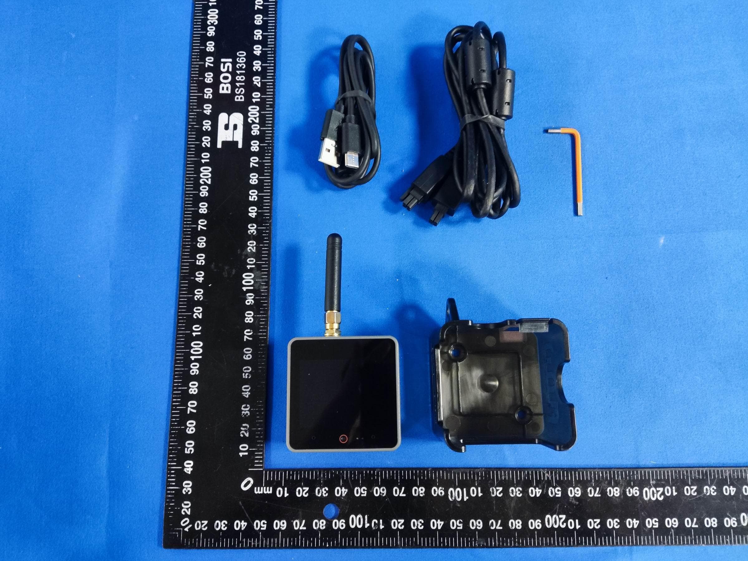
2AN3WM5FGV4
Sep 29, 2024Flow Gateway v4
Equipment Class
DTS - Digital Transmission System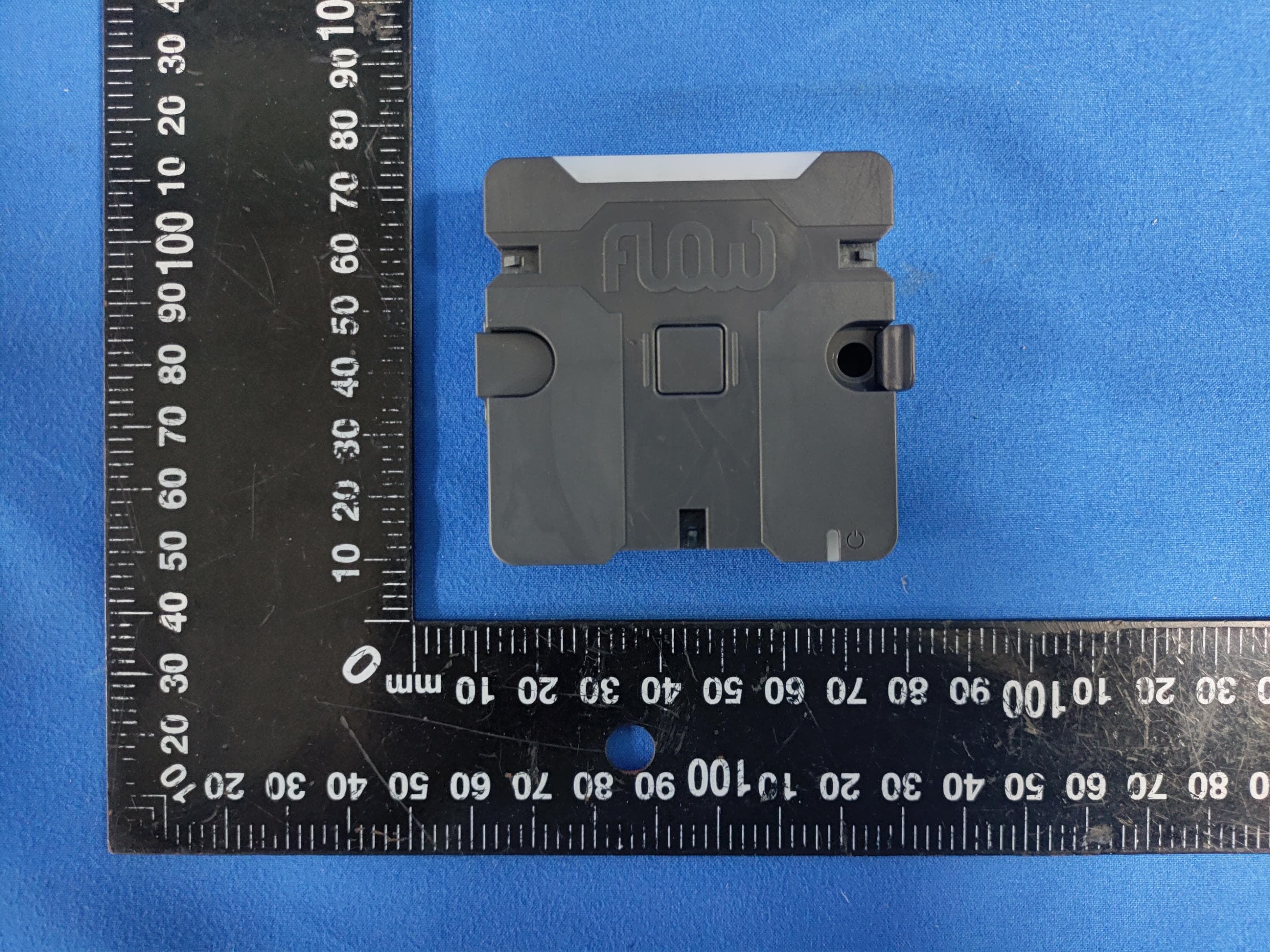
2AN3WM5FCV1
Sep 17, 2024Flow Connect
Equipment Class
DTS - Digital Transmission System
2AN3WM5DINMETER
Jul 22, 2024M5DinMeter
Equipment Class
DTS - Digital Transmission System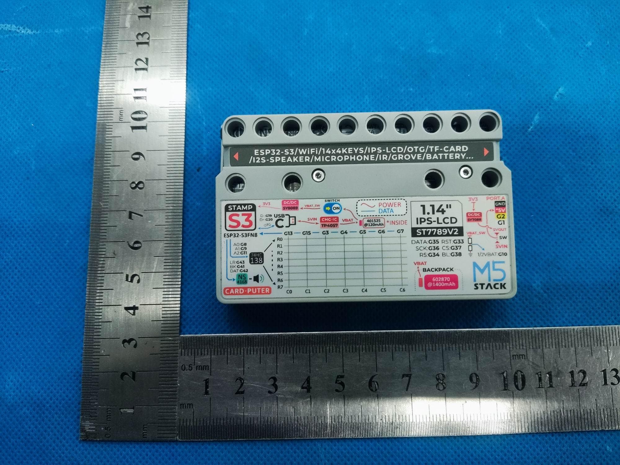
2AN3WM5CARDPUTER
Jul 21, 2024M5Cardputer
Equipment Class
DTS - Digital Transmission System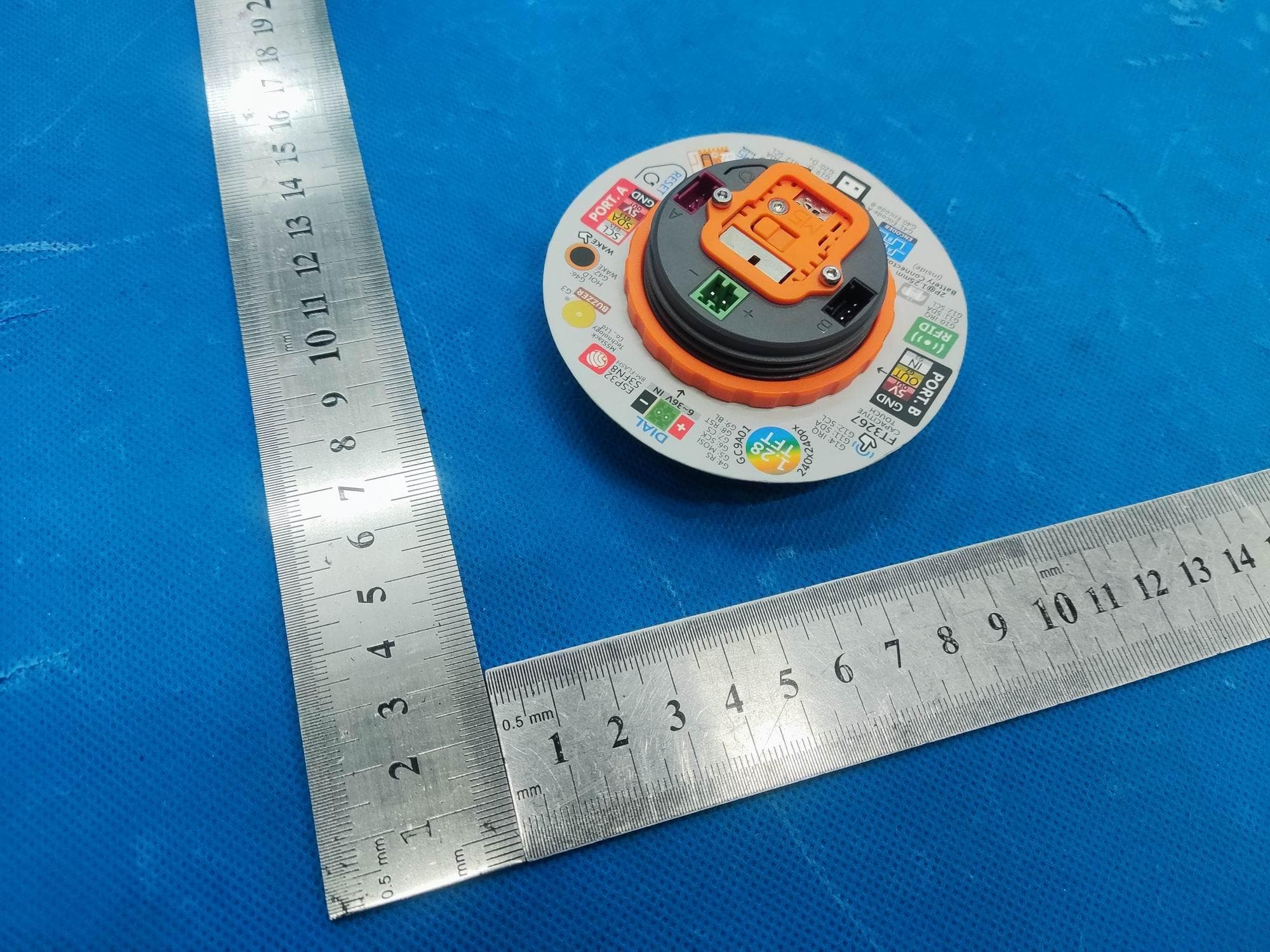
2AN3WM5DIAL
Jul 21, 2024M5Dial
Equipment Class
DTS - Digital Transmission System