2AN3WM5PAPERM5Paper
M5Stack Technology Co.,Ltd
Click to zoom
Application Details
- Equipment Class
- DSS - Part 15 Spread Spectrum Transmitter
- Date of Grant
- Nov 16, 2020
- Application Purpose
- Original Equipment
- Date of Application
- Nov 16, 2020
- Equipment Note
- M5Paper
- Frequency Range
- 2402.00000000 - 2480.00000000
- Company
- M5Stack Technology Co.,Ltd
- Country
- China
Documents & Files
Document Text
Text extracted from the exhibit documents filed with the FCC. Open a document above to read the original.
Users Manual
M5Paper 2020 V0 .0.1 Overview M5 Paper is a touchable ink screen controller device. This document will demonstrate how to use the device to test basic WIFI and Bluetooth functions. Development environment Arduino IDE Go to https://www.arduino.cc/en/main/software to download the Arduino IDE corresponding to your operating system and install it. Open the Arduino IDE and add the management address of the M5Stack board to the preferences https://m5stack.oss-cn- shenzhen.aliyuncs.com/resource/arduino/package_m5stack_index.json Search for "M5Stack" in the board management and download it. WiFi Use the official WIFI scanning case provided by ESP32 in the Example list to test Af ter uploading the program to the development board, open the serial monitor to view the WiFi scan results Bluetooth Demonstrate how to use classic Bluetooth to send messages through Bluetooth and transmit them to the serial port for printing. After uploading the program to the development board, use any Bluetooth serial debugging tool to pair and connect, and send messages. (The following will use the mobile phone Bluetooth serial port debugging app for demonstration) After the debugging tool sends a message, the device will receive the message and print it to the serial port. Overview M5 Paper is a touchable ink screen controller device, the controller adopts ESP32-D0WD. An electronic ink screen with a resolution of 540*960 @4.7" is embedded on the front, supporting 16-level grayscale display. With GT911 capacitive touch panel, it supports two-point touch and multiple gesture operations. Integrated dial wheel encoder, SD card slot, and physical buttons. An additional FM24C02 storage chip (256KB-EEPROM) is mounted for power-off storage of data. Built-in 1150mAh lithium battery, combined with the internal RTC (BM8563) can achieve sleep and wake-up functions, The device provides strong endurance. The opening of 3 sets of HY2.0-4P peripheral interfaces can expand more sensor devices. Product Features Embedded ESP32, support WiFi, Bluetooth Built-in 16MB Flash Low-power display panel Support two-point touch Nearly 180 degree viewing angle Human-computer interaction interface Built-in 1150mAh large capacity lithium battery Rich expansion interface Main Hardware ESP32-D0WD ESP32-D0WD is a System-in-Package (SiP) module that is based on ESP32, providing complete Wi-Fi and Bluetooth functionalities. The module integrates a 16MB SPI flash. ESP32-D0WD integrates all peripheral components seamlessly, including a crystal oscillator, flash, filter capacitors and RF matching links in one single package. 4.7” Ink screen modelEPD-ED047TC1 Resolution540 * 940 Display area58.32 * 103.68mm Grayscale16 Level Display driver chipIT8951 Pixel Pitch 0.108 * 0.108 mm GT911 Touch panel Built-in capacitive sensing circuit and high-performance MPU Report rate: 100Hz Outputs touch coordinates in real time Unified software applicable to capacitive touch screens of various sizes Single power supply, internal 1.8V LDO Flash embedded; In-system reprogrammable HotKnot integrated Interface M5Paper is equipped with Type-C USB interface and supports USB2.0 standard Pin map : The three sets of HY2.0-4P interfaces provided are connected to G25, G32, G26, G33, G18, G19 of ESP32 respectively InterfacePIN PORT.AG25, G32 PORT.BG26, G33 PORT.CG18, G19 FCC Statement: Any Changes or modifications not expressly approved by the party responsible for compliance could void the user’s authority to operate the equipment. This device complies with part 15 of the FCC Rules. Operation is subject to the following two conditions: (1) This device may not cause harmful interference,and (2) This device must accept any interference received, including interference that may cause undesired operation. Note: This equipment has been tested and found to comply with the limits for a Class B digital device,pursuant to part 15 of the FCC Rules. These limits are designed to provide reasonable protection against harmful interference in a residential installation. This equipment generates, uses and can radiate radio frequency energy and, if not installed and used in accordance with the instructions, may cause harmful interference to radio communications. However, there is no guarantee that interference will not occur in a particular installation. If this equipment does cause harmful interference to radio or television reception, which can be determined by turning the equipment off and on, the user is encouraged to try to correct the interference by one or more of the following measures: —Reorient or relocate the receiving antenna. —Increase the separation between the equipment and receiver. —Connect the equipment into an outlet on a circuit different from that to which the receiver is connected. —Consult the dealer or an experienced radio/TV technician for help. FCC Radiation Exposure Statement: This equipment complies with FCC radiation exposure limits set forth for an uncontrolled environment .This equipment should be installed and operated with minimum distance 20cm between the radiator& your body.
Cover Letter(s)
QA-FR-170-B Company: M5Stack Technology Co.,Ltd Add: 106,1st Floor,Building 1,Bright Technology Park,88 Zhuguang North Road,XiliTaoyuan Street,Nanshan District,Shenzhen,Guangdong,China Tel: 13509230623 Fax: 0755-69815195 FCC Authorization Date: 2020-09-01 FEDERAL COMMUNICATIONS COMMISSION Authorization and Evaluation Division 7435 Oakland Mills Road Columbia, MD 21046 Subject: Agent Authorization To whom it may concern: We, M5Stack Technology Co.,Ltd, the undersigned, Hereby authorizes Bay Area Compliance Laboratories Corporation to act on its behalf in all matters relating to application for Equipment authorization, including the signing of all documents relating to these matters. All acts carried out by Bay Area Compliance Laboratories Corp. on our behalf shall have the same effect as our own action. We, the undersigned, hereby certify that we are not subject to a denial of federal benefits, that includes FCC benefits, pursuant to Section 5301 of the Anti-Drug Abuse Act of 1988, 21 U.S.C. 862. This authorization is valid until further written notice from the applicant. Sincerely Yours, Signature: Typed or Printed Name: Jimmy Lai Title: CEO
External Photos
EXHIBIT A - EUT EXTERNAL PHOTOGRAPHS
Internal Photos
EXHIBIT B - EUT INTERNAL PHOTOGRAPHS Wi-Fi &BT Antenna
RF Exposure Info
Bay Area Compliance Laboratories Corp. (Kunshan) Report No.: RSHD200901002-00B FCC Part 15.247 Page 11 of 75 FCC §1.1310 & §2.1091- MAXIMUM PERMISSIBLE EXPOSURE (MPE) Applicable Standard According to subpart 15.247 (i) and subpart 1.1310, 2.1091 systems operating under the provisions of this section shall be operated in a manner that ensures the public is not exposed to RF energy level in excess of the communication guidelines. Limits for General Population/Uncontrolled Exposure Frequency Range (MHz) Electric Field Strength (V/m) Magnetic Field Strength (A/m) Power Density (mW/cm 2 ) Averaging Time (minutes) 0.3-1.34 614 1.63 *(100) 30 1.34-30 824/f 2.19/f *(180/f²) 30 30-300 27.5 0.073 0.2 30 300-1500 / f/1500 30 1500-100,000 / 1.0 30 f = frequency in MHz; * = Plane-wave equivalent power density Calculated Formulary: Predication of MPE limit at a given distance S = PG/4πR² = power density (in appropriate units, e.g. mW/cm 2 ); P = power input to the antenna (in appropriate units, e.g., mW); G = power gain of the antenna in the direction of interest relative to an isotropic radiator, the power gain factor, is normally numeric gain; R = distance to the center of radiation of the antenna (appropriate units, e.g., cm); Calculated Data (worst case): Mode Frequency Range (MHz) Maximum Antenna Gain Tune-up Conducted Power Evaluation Distance (cm) Power Density (mW/cm 2 ) MPE Limit (mW/cm 2 ) (dBi) (numeric)(dBm) (mW) 802.11b 2412-2462 2.00 1.58 23.00 199.53 20 0.0627 1.0 802.11g 2.00 1.58 25.00 316.23 20 0.0994 1.0 802.11n- HT20 2.00 1.58 25.00 316.23 20 0.0994 1.0 802.11n- HT40 2422-2452 2.00 1.58 23.00 199.53 20 0.0627 1.0 BLE 2402-2480 2.00 1.58 7.50 5.62 20 0.0018 1.0 BT3.0 2402-2480 2.00 1.58 9.00 7.94 20 0.0025 1.0 Note: 1. For the above tune up power were declared by the manufacturer. 2. Wi-Fi and BT/BLE can't transmit simultaneously. Result: The device meet FCC MPE at 20 cm distance.
Test Report
FCC PART 15.247 TEST REPORT For M5Stack Technology Co., Ltd 106, 1st Floor, Building 1, Bright Technology Park, 88 Zhuguang North Road, Xili Taoyuan Street, Nanshan District, Shenzhen, Guangdong, China FCC ID: 2AN3WM5PAPER Report Type: Original Report Product Type: M5Paper Test Engineer: CK Huang Re port Number: RSHD200901002-00B Re port Date: 2020-11-05 Reviewed B y: Oscar Ye EMC Manager Prepared By: Bay Area Compliance Laboratories Corp. (Kunshan) No.248 Chenghu Road,Kunshan,Jiangsu province,China Tel: +86-0512-86175000 Fax: +86-0512-88934268 www.baclcorp.com.cn Bay Area Compliance Laboratories Corp. (Kunshan) Report No.: RSHD200901002-00B FCC Part 15.247 Page 2 of 75 TABLE OF CONTENTS GENERAL INFORMATION ....................................................................................................................................... 4 PRODUCT DESCRIPTION FOR EQUIPMENT UNDER TEST (EUT) ..................................................................................... 4 OBJECTIVE ................................................................................................................................................................... 4 RELATED SUBMITTAL(S)/GRANT(S) ............................................................................................................................. 4 TEST METHODOLOGY .................................................................................................................................................. 4 MEASUREMENT UNCERTAINTY .................................................................................................................................... 5 TEST FACILITY ............................................................................................................................................................. 5 SYSTEM TEST CONFIGURATION .......................................................................................................................... 6 DESCRIPTION OF TEST CONFIGURATION ...................................................................................................................... 6 EUT EXERCISE SOFTWARE .......................................................................................................................................... 6 SPECIAL ACCESSORIES ................................................................................................................................................. 6 EQUIPMENT MODIFICATIONS ....................................................................................................................................... 6 SUPPORT EQUIPMENT LIST AND DETAILS .................................................................................................................... 7 EXTERNAL I/O CABLE .................................................................................................................................................. 7 BLOCK DIAGRAM OF TEST SETUP ................................................................................................................................ 7 SUMMARY OF TEST RESULTS ............................................................................................................................... 9 TEST EQUIPMENT LIST ......................................................................................................................................... 10 FCC §1.1310 & §2.1091- MAXIMUM PERMISSIBLE EXPOSURE (MPE) ............................................................ 11 APPLICABLE STANDARD ............................................................................................................................................ 11 CALCULATED FORMULARY: ....................................................................................................................................... 11 CALCULATED DATA (WORST CASE): .......................................................................................................................... 11 FCC §15.203 – ANTENNA REQUIREMENT .......................................................................................................... 12 APPLICABLE STANDARD ............................................................................................................................................ 12 ANTENNA CONNECTOR CONSTRUCTION .................................................................................................................... 12 FCC §15.207 (a) – AC LINE CONDUCTED EMISSIONS ..................................................................................... 13 APPLICABLE STANDARD ............................................................................................................................................ 13 EUT SETUP ................................................................................................................................................................ 13 EMI TEST RECEIVER SETUP ....................................................................................................................................... 13 TEST PROCEDURE ...................................................................................................................................................... 14 FACTOR & MARGIN CALCULATION ........................................................................................................................... 14 TEST RESULTS SUMMARY .......................................................................................................................................... 14 TEST DATA ................................................................................................................................................................ 14 FCC §15.205, §15.209 & §15.247(d) – RADIATED EMISSIONS ........................................................................... 17 APPLICABLE STANDARD .................................................................…
Text truncated - open the document above for the full version.
Test Setup Photos
EXHIBIT C - TEST SETUP PHOTOGRAPHS Conducted Emissions (Front View) Conducted Emissions (Side View) Radiated Emissions (Below 1GHz) Radiated Emissions (Above 1GHz)
Contact Information
Applicant
Jimmy Lai
Test Firm
Bay Area Compliance Laboratories Corp. (Kunshan)Mr. John Chan
[email protected]+86 0512 86175000
Technical Specifications
| # | Rule Parts | Frequency Range | Power Output |
|---|---|---|---|
| 1 | 15C | 2.40 GHz - 2.48 GHz | 7.00 mW |
Other Applications from M5Stack Technology Co.,Ltd
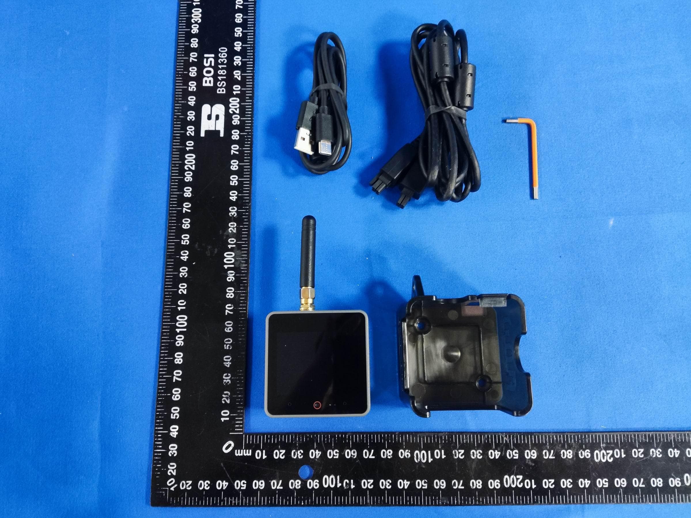
2AN3WM5FGV4
Sep 29, 2024Flow Gateway v4
Equipment Class
DTS - Digital Transmission System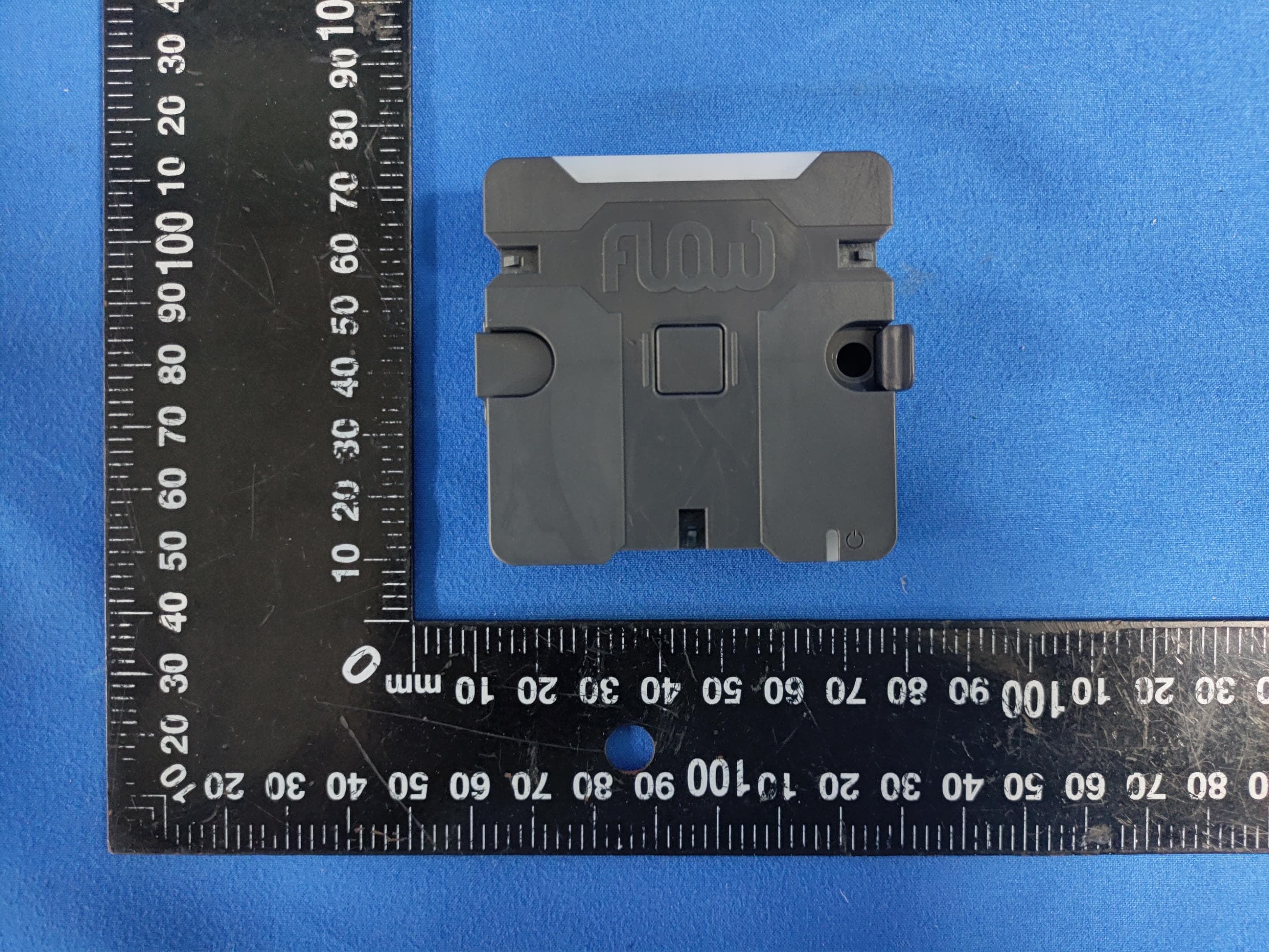
2AN3WM5FCV1
Sep 17, 2024Flow Connect
Equipment Class
DTS - Digital Transmission System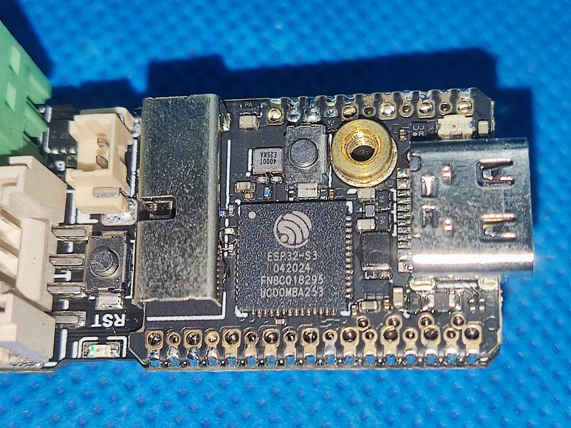
2AN3WM5DINMETER
Jul 22, 2024M5DinMeter
Equipment Class
DTS - Digital Transmission System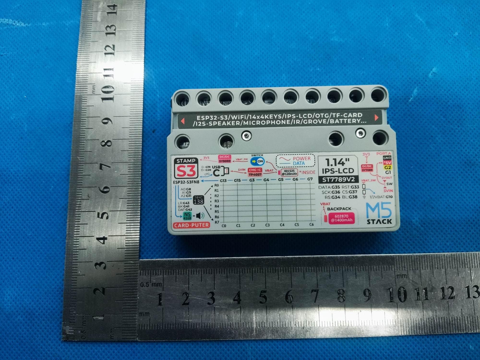
2AN3WM5CARDPUTER
Jul 21, 2024M5Cardputer
Equipment Class
DTS - Digital Transmission System
2AN3WM5DIAL
Jul 21, 2024M5Dial
Equipment Class
DTS - Digital Transmission System