2AN3WM5STACK-CORE2M5Stack-CORE2
M5Stack Technology Co.,Ltd
Click to zoom
Application Details
- Equipment Class
- DTS - Digital Transmission System
- Date of Grant
- Aug 19, 2020
- Application Purpose
- Original Equipment
- Date of Application
- Aug 19, 2020
- Equipment Note
- M5Stack-CORE2
- Frequency Range
- 2412.00000000 - 2462.00000000
- Company
- M5Stack Technology Co.,Ltd
- Country
- China
Documents & Files
Document Text
Text extracted from the exhibit documents filed with the FCC. Open a document above to read the original.
Users Manual
M5STACK- CORE2 2020 V0.01 1. OUTLINE M5Stick CORE2 is ESP32 board which based on ESP32-D0WDQ6-V3 chip, contained 2-inch TFT screen. The board is made of PC+ABC. 1.1 Hardware Composition The hardware of CORE2: ESP32-D0WDQ6-V3 chip, TFT screen, Green LED, Button, GROVE interface, TypeC-to-USB interface, Power Management chip and battery. ESP32-D0WDQ6-V3 The ESP32 is a dual-core system with two Harvard Architecture Xtensa LX6 CPUs. All embedded memory,external memory and peripherals are located on the data bus and/or the instruction bus of these CPUs.With some minor exceptions (see below), the address mapping of two CPUs is symmetric, meaning that they usethe same addresses to access the same memory. Multiple peripherals in the system can access embeddedmemory via DMA. TFT Screen is a 2-inch color screen driven ILI9342C with a resolution of 320 x 240. Operating voltage range is 2.6~3.3V, working temperature range is -25~55°C. Power Management chip is X-Powers's AXP192. The operating voltage range is 2.9V~6.3V and the charging current is 1.4A. CORE2 equips ESP32 with everything needed for programming, everything needed for operation and development 2. PIN DESCRIPTION 2.1. USB INTERFACE M5CAMREA Configuration Type-C type USB interface, support USB2.0 standard communication protocol. 2.2. GROVE INTERFACE 4p disposed pitch of 2.0mm M5CAMREA GROVE interfaces, internal wiring and GND, 5V, GPIO32, GPIO33 connected. 3. FUNCTIONAL DESCRIPTION This chapter describes the ESP32-D0WDQ6-V3 various modules and functions. 3.1. CPU AND MEMORY Xtensa®single-/dual-core32-bitLX6microprocessor(s), upto600MIPS (200MIPSforESP32-S0WD/ESP32-U4WDH, 400 MIPS for ESP32-D2WD): ⚫448 KB ROM ⚫520 KB SRAM ⚫16 KB SRAM in RTC ⚫QSPI supports multiple flash/SRAM chips 3.2. STORAGE DESCRIPTION 3.2.1. External Flash and SRAM ESP32 support multiple external QSPI flash and static random access memory (SRAM), having a hardware-based AES encryption to protect the user programs and data. ⚫ESP32 access external QSPI Flash and SRAM by caching. Up to 16 MB external Flash code space is mapped into the CPU, supports 8-bit, 16-bit and 32-bit access, and can execute code. ⚫Up to 8 MB external Flash and SRAM mapped to the CPU data space, support for 8-bit, 16-bit and 32-bit access. Flash supports only read operations, SRAM supports read and write operations. 3.3. CRYSTAL External 2 MHz~60 MHz crystal oscillator (40 MHz only for Wi-Fi/BT functionality) 3.4. RTC MANAGEMENT AND LOW POWER CONSUMPTION ESP32 uses advanced power management techniques may be switched between different power saving modes. (See Table 5). •Power saving mode - Active Mode: RF chip is operating. Chip may receive and transmit a sounding signal. - Modem-sleep mode: CPU can run, the clock may be configured. Wi-Fi / Bluetooth baseband and RF - Light-sleep mode: CPU suspended. RTC and memory and peripherals ULP coprocessor operation. Any wake-up event (MAC, host, RTC timer or external interrupt) will wake up the chip. - Deep-sleep mode: only the RTC memory and peripherals in a working state. Wi- Fi and Bluetooth connectivity data stored in the RTC. ULP coprocessor can work. - Hibernation Mode: 8 MHz oscillator and a built-in coprocessor ULP are disabled. RTC memory to restore the power supply is cut off. Only one RTC clock timer located on the slow clock and some RTC GPIO at work. RTC RTC clock or timer can wake up from the GPIO Hibernation mode. •Deep-sleep mode - related sleep mode: power save mode switching between Active, Modem-sleep, Light-sleep mode. CPU, Wi-Fi, Bluetooth, and radio preset time interval to be awakened, to ensure connection Wi-Fi / Bluetooth. - Ultra Low-power sensor monitoring methods: the main system is Deep-sleep mode, ULP coprocessor is periodically opened or closed to measure sensor data. The sensor measures data, ULP coprocessor decide whether to wake up the main system. Functions in different power consumption modes: TABLE 5 4. ELECTRICAL CHARACTERISTICS 4.1. LIMIT PARAMETERS Table 8: Limiting values 1.V IO to the power supply pad, Refer ESP32 Technical Specification Appendix IO_MUX, as SD_CLK of Power supply for VDD_SDIO. Press and hold the side power button for two seconds to start the device.Press and hold for more than 6 seconds to turn off the device. Switch to the photo mode through the Home screen, and the avatar that can be obtained through the camera is displayed on the tft screen.The USB cable must be connected when working, and the lithium battery is used for short-term storage to prevent power failure. FCC Statement: Any Changes or modifications not expressly approved by the party responsible for compliance could void the user's authority to operate the equipment. This device complies with part 15 of the FCC Rules. Operation is subject to the following two conditions: (1) This device may not cause harmful interference, and (2) This device must accept any interference received, including interference that may cause undesired operation. FCC Radiation Exposure Statement: This equipment complies with FCC radiation exposure limits set forth for an uncontrolled environment .This equipment should be installed and operated with minimum distance 20cm between the radiator& your body. Note: This equipment has been tested and found to comply with the limits for a Class B digital device, pursuant to part 15 of the FCC Rules. These limits are designed to provide reasonable protection against harmful interference in a residential installation. This equipment generates, uses and can radiate radio frequency energy and, if not installed and used in accordance with the instructions, may cause harmful interference to radio communications. However, there is no guarantee that interference will not occur in a particular installation. If this equipment does cause harmful interference to radio or television reception, which can be determined by turning the equipment off and on, the user is encouraged to try to correct the interference by one or more of the fol…
Text truncated - open the document above for the full version.
External Photos
EXHIBIT A - EUT EXTERNAL PHOTOGRAPHS
Internal Photos
EXHIBIT B - EUT INTERNAL PHOTOGRAPHS Wi-Fi &BLE&BT Antenna
RF Exposure Info
Bay Area Compliance Laboratories Corp. (Kunshan) Report No.: RSHD200716003-00A FCC Part 15.247 Page 14 of 84 FCC §15.247 (I) & §1.1310 & §2.1091 - MAXIMUM PERMISSIBLE EXPOSURE (MPE) Applicable Standard According to subpart 15.247 (i) and subpart 1.1310, 2.1091 systems operating under the provisions of this section shall be operated in a manner that ensures the public is not exposed to RF energy level in excess of the communication guidelines. Limits for General Population/Uncontrolled Exposure Frequency Range (MHz) Electric Field Strength (V/m) Magnetic Field Strength (A/m) Power Density (mW/cm 2 ) Averaging Time (minutes) 0.3-1.34 614 1.63 *(100) 30 1.34-30 824/f 2.19/f *(180/f²) 30 30-300 27.5 0.073 0.2 30 300-1500 / f/1500 30 1500-100,000 / 1.0 30 f = frequency in MHz; * = Plane-wave equivalent power density Calculated Formulary: Predication of MPE limit at a given distance S = PG/4πR² = power density (in appropriate units, e.g. mW/cm 2 ); P = power input to the antenna (in appropriate units, e.g., mW); G = power gain of the antenna in the direction of interest relative to an isotropic radiator, the power gain factor, is normally numeric gain; R = distance to the center of radiation of the antenna (appropriate units, e.g., cm); Calculated Data: Mode Frequency Range (MHz) Maximum Antenna Gain Tune-up Conducted Power Evaluation Distance (cm) Power Density (mW/cm 2 ) MPE Limit (mW/cm 2 ) (dBi) (numeric)(dBm) (mW) 802.11b 2412-2462 2.00 1.58 22.50 177.83 20 0.0559 1.0 802.11g 2.00 1.58 21.50 141.25 20 0.0444 1.0 802.11n- HT20 2.00 1.58 22.00 158.49 20 0.0498 1.0 802.11n- HT40 2422-2452 2.00 1.58 22.50 177.83 20 0.0559 1.0 BLE 2402-2480 2.00 1.58 4.50 2.82 20 0.0009 1.0 BT 2402-2480 2.00 1.58 7.00 5.01 20 0.0016 1.0 Note: 1. For the above tune up power were declared by the manufacturer. 2. Wi-Fi and BT/BLE can't transmit simultaneously. Result: The device meet FCC MPE at 20 cm distance.
Test Report
FCC PART 15.247 TEST REPORT For M5Stack Technology Co., Ltd 106, 1st Floor, Building 1, Bright Technology Park, 88 Zhuguang North Road, Xili Taoyuan Street, Nanshan District, Shenzhen, Guangdong, China FCC ID: 2AN3WM5STACK-CORE2 Report Type: Original Report Product Type: M5Stack-CORE2 Test Engineer: Lee Li Re port Number: RSHD200716003-00A Re port Date: 2020-08-04 Reviewed B y: Oscar Ye EMC Manager Prepared By: Bay Area Compliance Laboratories Corp. (Kunshan) No.248 Chenghu Road, Kunshan, Jiangsu province, China Tel: +86-0512-86175000 Fax: +86-0512-88934268 www.baclcorp.com.cn Bay Area Compliance Laboratories Corp. (Kunshan) Report No.: RSHD200716003-00A FCC Part 15.247 Page 2 of 84 1 TABLE OF CONTENTS GENERAL INFORMATION ....................................................................................................................................... 4 PRODUCT DESCRIPTION FOR EQUIPMENT UNDER TEST (EUT) ..................................................................................... 4 OBJECTIVE ................................................................................................................................................................... 4 RELATED SUBMITTAL(S)/GRANT(S) ............................................................................................................................. 4 TEST METHODOLOGY .................................................................................................................................................. 4 MEASUREMENT UNCERTAINTY .................................................................................................................................... 5 TEST FACILITY ............................................................................................................................................................. 5 SYSTEM TEST CONFIGURATION .......................................................................................................................... 6 DESCRIPTION OF TEST CONFIGURATION ...................................................................................................................... 6 EQUIPMENT MODIFICATIONS ....................................................................................................................................... 6 EUT EXERCISE SOFTWARE .......................................................................................................................................... 7 SUPPORT EQUIPMENT LIST AND DETAILS .................................................................................................................. 10 EXTERNAL I/O CABLE ................................................................................................................................................ 10 BLOCK DIAGRAM OF TEST SETUP .............................................................................................................................. 10 SUMMARY OF TEST RESULTS ............................................................................................................................. 12 TEST EQUIPMENT LIST ......................................................................................................................................... 13 FCC §15.247 (I) & §1.1310 & §2.1091 - MAXIMUM PERMISSIBLE EXPOSURE (MPE) .................................. 14 APPLICABLE STANDARD ............................................................................................................................................ 14 CALCULATED FORMULARY: ....................................................................................................................................... 14 CALCULATED DATA: .................................................................................................................................................. 14 FCC §15.203 - ANTENNA REQUIREMENT ........................................................................................................... 15 APPLICABLE STANDARD ............................................................................................................................................ 15 ANTENNA CONNECTOR CONSTRUCTION .................................................................................................................... 15 FCC §15.207 (a) – AC LINE CONDUCTED EMISSIONS ..................................................................................... 16 APPLICABLE STANDARD ............................................................................................................................................ 16 EUT SETUP ................................................................................................................................................................ 16 EMI TEST RECEIVER SETUP ....................................................................................................................................... 16 TEST PROCEDURE ...................................................................................................................................................... 17 FACTOR & OVER LIMIT CALCULATION ...................................................................................................................... 17 TEST RESULTS SUMMARY .......................................................................................................................................... 17 TEST DATA ................................................................................................................................................................ 17 FCC §15.209, §15.205 & §15.247(d) - SPURIOUS EMISSIONS ............................................................................. 22 APPLICABLE STANDARD ............................................................................................................................................ 22 EUT SETUP ..................................................................…
Text truncated - open the document above for the full version.
Test Setup Photos
EXHIBIT C - TEST SETUP PHOTOGRAPHS Conducted Emissions (Front View) Conducted Emissions (Side View) Radiated Emissions (Below 1GHz) Radiated Emissions (Above 1GHz)
Contact Information
Applicant
Jimmy Lai
Test Firm
Bay Area Compliance Laboratories Corp. (Kunshan)Mr. John Chan
[email protected]+86 0512 86175000
Technical Specifications
| # | Rule Parts | Frequency Range | Power Output |
|---|---|---|---|
| 2 | 15C | 2.41 GHz - 2.46 GHz | 173.00 mW |
Other Applications from M5Stack Technology Co.,Ltd
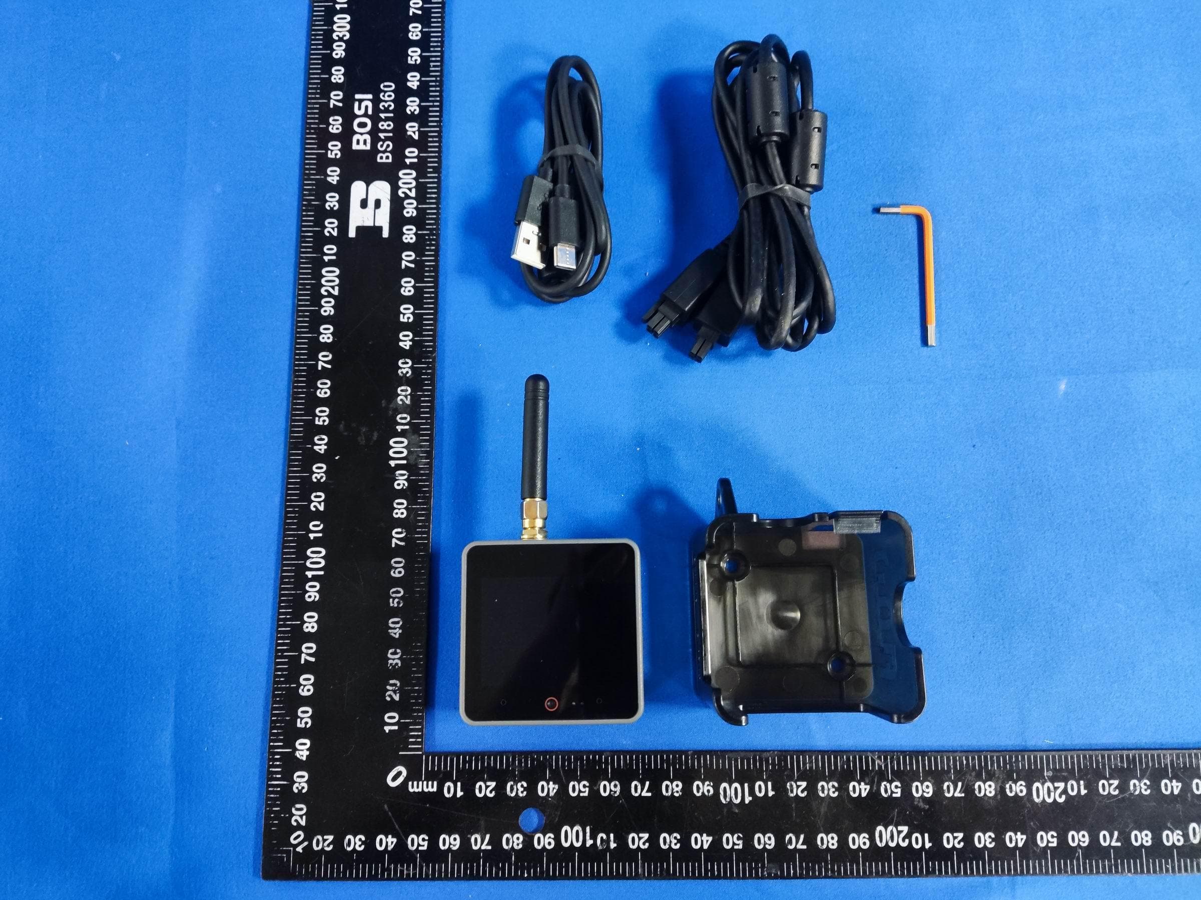
2AN3WM5FGV4
Sep 29, 2024Flow Gateway v4
Equipment Class
DTS - Digital Transmission System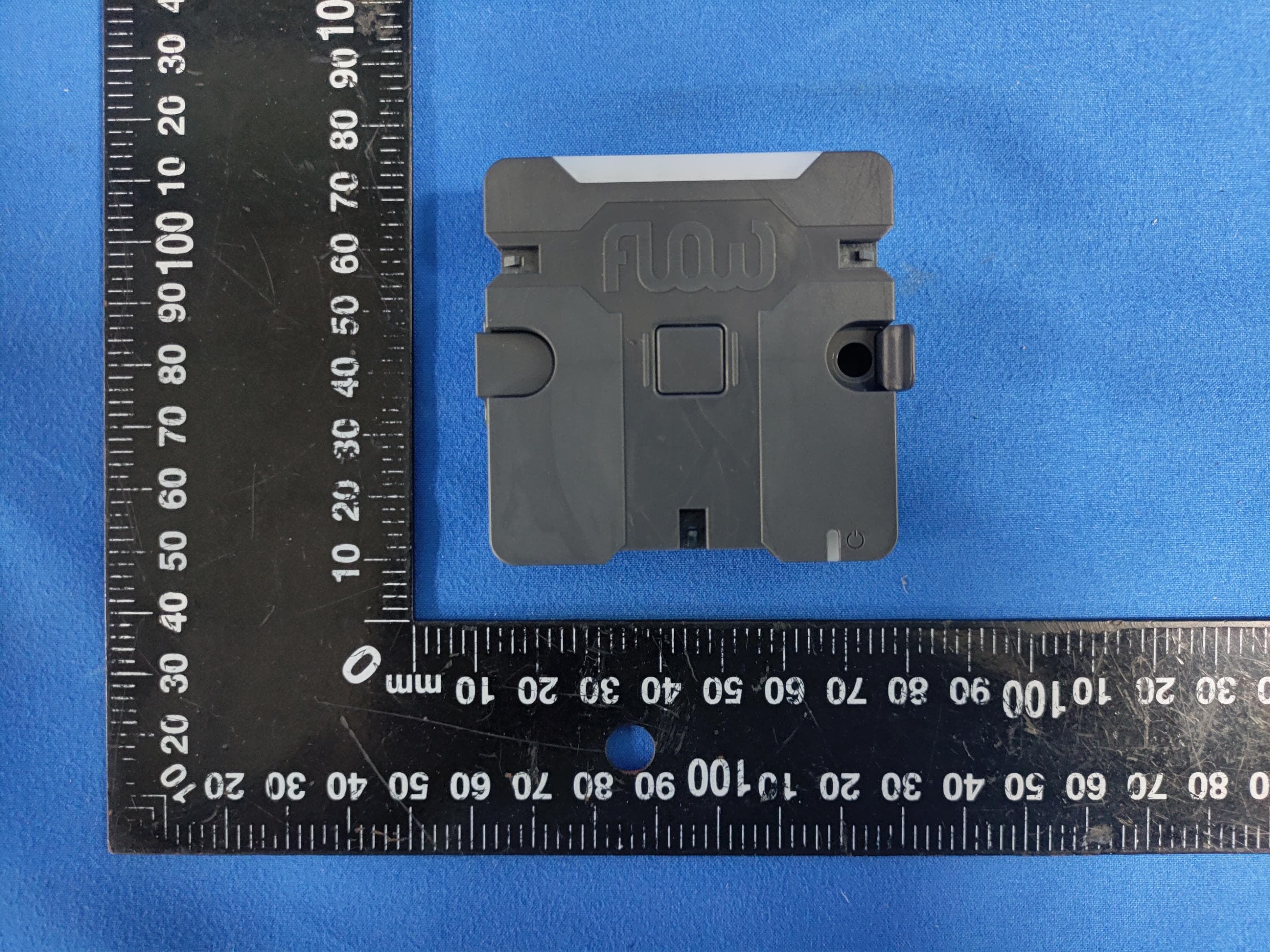
2AN3WM5FCV1
Sep 17, 2024Flow Connect
Equipment Class
DTS - Digital Transmission System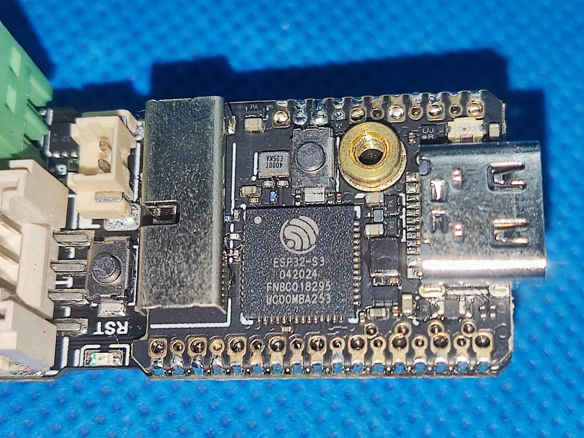
2AN3WM5DINMETER
Jul 22, 2024M5DinMeter
Equipment Class
DTS - Digital Transmission System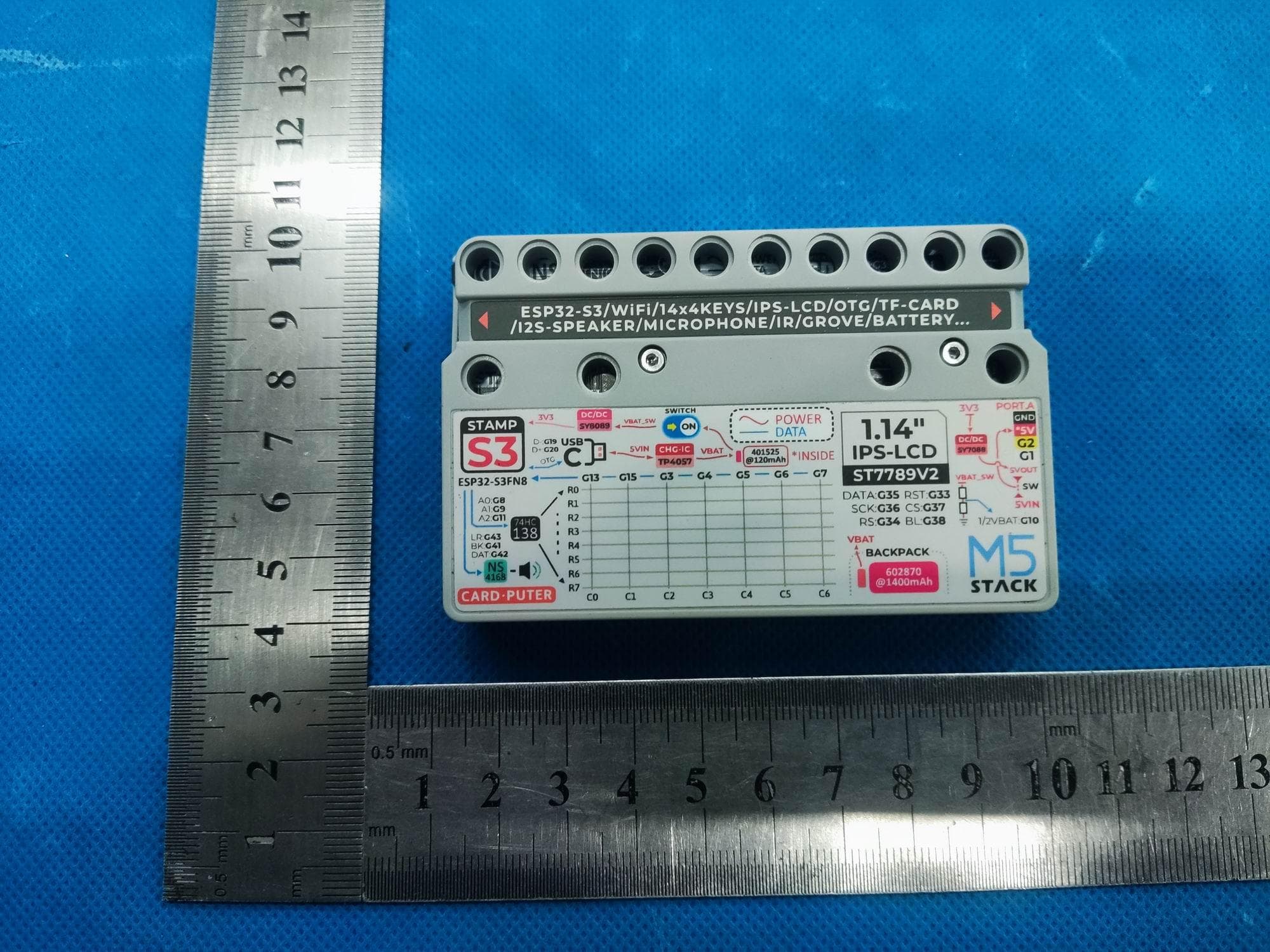
2AN3WM5CARDPUTER
Jul 21, 2024M5Cardputer
Equipment Class
DTS - Digital Transmission System
2AN3WM5DIAL
Jul 21, 2024M5Dial
Equipment Class
DTS - Digital Transmission System