2AN3WM5STAMP-PICOM5STAMP
M5Stack Technology Co.,Ltd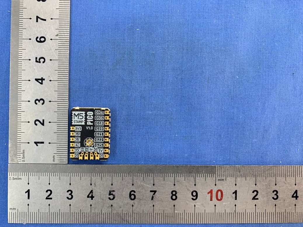
Click to zoom
Application Details
- Equipment Class
- DSS - Part 15 Spread Spectrum Transmitter
- Date of Grant
- Jul 26, 2021
- Application Purpose
- Original Equipment
- Date of Application
- Jul 26, 2021
- Equipment Note
- M5STAMP
- Frequency Range
- 2402.00000000 - 2480.00000000
- Company
- M5Stack Technology Co.,Ltd
- Country
- China
Documents & Files
Document Text
Text extracted from the exhibit documents filed with the FCC. Open a document above to read the original.
Users Manual
M5STACK PICO 2021 CONTENTS 1.OUTLINE ............................................................................................................................. 3 2.SPECIFICATIONS ............................................................................................................. 4 3.QUICK START .................................................................................................................... 5 3.1. ARDUINO IDE ............................................................................................................................ 5 3.2. BLUETOOTH SERIAL ....................................................................................................................... 6 3.3. WIFI SCANNING ............................................................................................................................ 7 1. OUTLINE S TAMP-PICO is the smallest ESP32 system board launched by M5Stack. It focuses on cost-effectiveness and simplification. It embeds an ESP32-PICO-D4 IoT control on a small and exquisite PCB board as small as a stamp (STAMP). core. With the support of ESP32, this development board integrates 2.4GHz Wi-Fi and Bluetooth dual-mode solutions. Provide 12 IO expansion pins and a programmable RGB LED, combined with ESP32 internal interface resources (UART, I2C, SPI, etc.), can expand various peripheral sensors. It can be embedded in all kinds of IoT devices as the control core. 2.SPECIFICATIONS Resources Parameter Processor ESP32- PICO-D4 240MHz dual core, 600 DMIPS, 520KB SRAM, Wi-Fi, dual mode Bluetooth Flash 4MB Input voltage 5V @ 500mA button Programmable buttons x 1 Programmable RGB LED SK6812 x 1 Antenna PIFA Antenna IO x12 G0, G1, G3, G26, G36, G18, G19, G21, G22, G25, G32, G33 Operating temperature 32°F to 104°F ( 0°C to 40°C ) 3. QUICK START S TAMP-PICO adopts the most streamlined circuit design, so it does not include a program download circuit. When users use it, they can download the program through a USB-TTL burner. The wiring method is shown in the figure below. 3.1. ARDUINO IDE Visit Arduino's official website(https://www.arduino.cc/en/Main/Software),Select the installation package for your own operating system to download. >1.Open up Arduino IDE, navigate to `File`->`Peferences`->`Settings` >2.Copy the following M5Stack Boards Manager url to `Additional Boards Manager URLs:` https://m5stack.oss-cn-shenzhen.aliyuncs.com/resource/arduino/package_m5stack_index.json > 3.Navigate to `Tools`->`Board:`->`Boards Manager...` >4.Search `M5Stack` in the pop-up window, find it and click `Install` >5.select `Tools`->`Board:`->`M5Stack-M5StickC (ESP32-PI CO-D4 used the same as STAMP- PICO)` 3.2. BLUETOOTH SERIAL O pen the Arduino IDE and open the example program `File`->`Examples`->`BluetoothSerial`->`SerialToSerialBT`. Connect the device to the computer and select the corresponding port to burn. After completion, the device will automatically run Bluetooth, and the device name is `ESP32test`. At this time, use the Bluetooth serial port sending tool on the PC to realize the transparent transmission of Bluetooth serial data. #include "BluetoothSerial.h" #if !defined(CONFIG_BT_ENABLED) || !defined(CONFIG_BLUEDROID_ENABLED) #error Bluetooth is not enabled! Please run `make menuconfig` to and en able it #endif BluetoothSerial SerialBT; void setup() { S erial.begin(115200); S erialBT.begin("ESP32test"); //Bluetooth device name S erial.println("The device started, now you can pair it with bluetoot h!"); } void loop() { i f (Serial.available()) { S erialBT.write(Serial.read()); } i f (SerialBT.available()) { S erial.write(SerialBT.read()); } d elay(20); } 3.3. WIFI SCANNING O pen the Arduino IDE and open the example program `File`->`Examples`->`WiFi`->`WiFiScan`. Connect the device to the computer and select the corresponding port to burn. After completion, the device will automatically run the WiFi scan, and the current WiFi scan result can be obtained through the serial port monitor that comes with the Arduino. #include "WiFi.h" void setup() { Serial.begin(115200); // Set WiFi to station mode and disconnect from an AP if it was pre viously connected WiFi .mode (WIFI_STA); WiFi .disconnect(); delay(100 ); Serial.println(" Setup done "); } void loop () { Serial.println(" scan start"); // WiFi.scanNetworks will return the number of networks found int n = WiFi .scanNetworks(); Serial.println(" scan done "); if (n == 0) { Serial.println(" no networks found"); } else { Serial.print(n); Serial.println(" networks found"); for (int i = 0; i < n; ++ i) { // Print SSID and RSSI for each network found Serial.print(i + 1); Serial.print(" : "); Serial.print(WiFi .SSID (i)); Serial.print(" ("); Serial.print(WiFi .RSSI (i)); Serial.print(" )"); Serial.println(( WiFi .encryptionType(i) == WIFI_AUTH_OPEN)?" ":"*"); delay(10 ); } } Serial.println(""); // Wait a bit before scanning again delay(5000 ); } FCC Statement: Any Changes or modifications not expressly approved by the party responsible for compliance could void the user’s authority to operate the equipment. This device complies with part 15 of the FCC Rules. Operation is subject to the following two conditions: (1) This device may not cause harmful interference, and (2) This device must accept any interference received, including interference that may cause undesired operation. FCC Radiation Exposure Statement: This equipment complies with FCC radiation exposure limits set forth for an uncontrolled environment .This equipment should be installed and operated with minimum distance 20cm between the radiator& your body. Note: This equipment has been tested and found to comply with the limits for a Class B digital device, pursuant to part 15 of the FCC Rules. These limits are designed to provide reasonable protection against harmful interference in a residential installation. This equipment generates uses and can radiate radio frequency energy and, if not installed and used in accordance with the instructions,…
Text truncated - open the document above for the full version.
Cover Letter(s)
Q A-FR-171-A Company: M5Stack Technology Co., Ltd Add: 106,1st Floor,Building 1,Bright Technology Park 88 Zhuguang North Road,XiliTaoyuan Street,Nanshan District,Shenzhen,Guangdong,China Tel: 13509230623 Fax: 0755-69815195 E-mail: [email protected] FCC Confidential Authorization Da te: 2021-04-29 FEDERAL COMMUNICATIONS COMMISSIONS Authorization and Evaluation Division 7435 Oakland Mills Road Columbia, MD 21046 Subject: Confidentiality Request regarding application for certification of FCC ID: 2AN3WM5STAMP-PICO In accordance with Sections 0.457 and 0.459 of the Commission’s Rules, M5Stack Technology Co., Ltd hereby requests long-term confidential treatment of information accompanying this application as outlined below: Block Diagram Schemati cs Operation Description Th e above materials contain proprietary and confidential information not customarily released to the public. The public disclosure of these materials provides unjustified benefits to its competitors in the market. Sincerely, Signature: Printer Name: Jimmy Lai Title : CEO
External Photos
EXHIBIT A - EUT EXTERNAL PHOTOGRAPHS 2 3
ID Label/Location Info
Model: PICO FCC ID: 2AN3WM5STAMP-PICO
Internal Photos
EXHIBIT B - EUT INTERNAL PHOTOGRAPHS Antenna
RF Exposure Info
Bay Area Compliance Laboratories Corp. (Kunshan) Report No.: RSHD210429002-00C FCC Part 15.247 Page 11 of 76 FCC §1.1310 & §2.1091- MAXIMUM PERMISSIBLE EXPOSURE (MPE) Applicable Standard According to subpart 15.247 (i) and subpart 1.1310, 2.1091 systems operating under the provisions of this section shall be operated in a manner that ensures the public is not exposed to RF energy level in excess of the communication guidelines. Limits for General Population/Uncontrolled Exposure Frequency Range (MHz) Electric Field Strength (V/m) Magnetic Field Strength (A/m) Power Density (mW/cm 2 ) Averaging Time (minutes) 0.3-1.34 614 1.63 *(100) 30 1.34-30 824/f 2.19/f *(180/f²) 30 30-300 27.5 0.073 0.2 30 300-1500 / f/1500 30 1500-100,000 / 1.0 30 f = frequency in MHz; * = Plane-wave equivalent power density Calculated Formulary: Predication of MPE limit at a given distance S = PG/4πR² = power density (in appropriate units, e.g. mW/cm 2 ); P = power input to the antenna (in appropriate units, e.g., mW); G = power gain of the antenna in the direction of interest relative to an isotropic radiator, the power gain factor, is normally numeric gain; R = distance to the center of radiation of the antenna (appropriate units, e.g., cm); Bay Area Compliance Laboratories Corp. (Kunshan) Report No.: RSHD210429002-00C FCC Part 15.247 Page 12 of 76 Calculated Data (worst case): Mode Frequency Range (MHz) Maximum Antenna Gain Tune-up Conducted Power Evaluation Distance (cm) Power Density (mW/cm 2 ) MPE Limit (mW/cm 2 ) (dBi) (numeric) (dBm) (mW) Wi-Fi 802.11b 2412-2462 2.0 1.58 20.00 100.00 20 0.0314 1.0 Wi-Fi 802.11g 2.0 1.58 23.00 199.53 20 0.0627 1.0 Wi-Fi 802.11n- HT20 2.0 1.58 23.00 199.53 20 0.0627 1.0 Wi-Fi 802.11n- HT40 2422-2452 2.0 1.58 23.00 199.53 20 0.0627 1.0 BLE 2402-2480 2.0 1.58 13.00 19.95 20 0.0063 1.0 BT 2402-2480 2.0 1.58 12.50 17.78 20 0.0056 1.0 Note 1:Wi-Fi and BT /BLE cannot transmit simultaneously. Note 2: The tune-up power is declared by manufacturer. Conclusion: The device meets MPE at distance 20cm.
Test Report
FCC PART 15.247 TEST REPORT For M5Stack Technology Co., Ltd 106,1st Floor,Building 1,Bright Technology Park 88 Zhuguang North Road,XiliTaoyuan Street,Nanshan District,Shenzhen,Guangdong,China FCC ID: 2AN3WM5STAMP-PICO Report Type: Original Report Product Type: M5STAMP Project Engineer: Stone Zhang Report Number: RSHD210429002-00C Report Date: 2021-06-28 Reviewed By: Oscar Ye EMC Manager Prepared By: Bay Area Compliance Laboratories Corp. (Kunshan) No.248 Chenghu Road,Kunshan,Jiangsu province,China Tel: +86-0512-86175000 Fax: +86-0512-88934268 www.baclcorp.com.cn Bay Area Compliance Laboratories Corp. (Kunshan) Report No.: RSHD210429002-00C FCC Part 15.247 Page 2 of 76 TABLE OF CONTENTS GENERAL INFORMATION ....................................................................................................................................... 4 PRODUCT DESCRIPTION FOR EQUIPMENT UNDER TEST (EUT) ..................................................................................... 4 OBJECTIVE ................................................................................................................................................................... 4 RELATED SUBMITTAL(S)/GRANT(S) ............................................................................................................................. 4 TEST METHODOLOGY .................................................................................................................................................. 5 MEASUREMENT UNCERTAINTY .................................................................................................................................... 5 TEST FACILITY ............................................................................................................................................................. 5 SYSTEM TEST CONFIGURATION .......................................................................................................................... 6 DESCRIPTION OF TEST CONFIGURATION ...................................................................................................................... 6 EUT EXERCISE SOFTWARE .......................................................................................................................................... 6 SPECIAL ACCESSORIES ................................................................................................................................................. 6 EQUIPMENT MODIFICATIONS ....................................................................................................................................... 6 SUPPORT EQUIPMENT LIST AND DETAILS .................................................................................................................... 7 EXTERNAL I/O CABLE .................................................................................................................................................. 7 BLOCK DIAGRAM OF TEST SETUP ................................................................................................................................ 7 SUMMARY OF TEST RESULTS ............................................................................................................................... 9 TEST EQUIPMENT LIST ......................................................................................................................................... 10 FCC §1.1310 & §2.1091- MAXIMUM PERMISSIBLE EXPOSURE (MPE) ............................................................ 11 FCC §15.203 – ANTENNA REQUIREMENT .......................................................................................................... 13 APPLICABLE STANDARD ............................................................................................................................................ 13 ANTENNA CONNECTOR CONSTRUCTION .................................................................................................................... 13 FCC §15.207 (a) – AC LINE CONDUCTED EMISSIONS ..................................................................................... 14 APPLICABLE STANDARD ............................................................................................................................................ 14 EUT SETUP ................................................................................................................................................................ 14 EMI TEST RECEIVER SETUP ....................................................................................................................................... 14 TEST PROCEDURE ...................................................................................................................................................... 15 FACTOR & MARGIN CALCULATION ........................................................................................................................... 15 TEST RESULTS SUMMARY .......................................................................................................................................... 15 TEST DATA ................................................................................................................................................................ 15 FCC §15.205, §15.209 & §15.247(d) – RADIATED EMISSIONS ........................................................................... 18 APPLICABLE STANDARD ............................................................................................................................................ 18 EUT SETUP ................................................................................................................................................................ 18 EMI TEST RECEIVER SETUP ....................................................................................................................................... 19 TEST PROCEDURE ....................................................…
Text truncated - open the document above for the full version.
Test Setup Photos
EXHIBIT C - TEST SETUP PHOTOGRAPHS Conducted Emissions (Front View) Conducted Emissions (Side View) Radiated Emissions (Below 1GHz) Radiated Emissions (Above 1GHz)
Contact Information
Applicant
Jimmy Lai
Test Firm
Bay Area Compliance Laboratories Corp. (Kunshan)Mr. John Chan
[email protected]+86 0512 86175000
Technical Specifications
| # | Rule Parts | Frequency Range | Power Output |
|---|---|---|---|
| 1 | 15C | 2.40 GHz - 2.48 GHz | 18.00 mW |
Other Applications from M5Stack Technology Co.,Ltd
2AN3WM5FGV4
Sep 29, 2024Flow Gateway v4
Equipment Class
DTS - Digital Transmission System
2AN3WM5FCV1
Sep 17, 2024Flow Connect
Equipment Class
DTS - Digital Transmission System
2AN3WM5DINMETER
Jul 22, 2024M5DinMeter
Equipment Class
DTS - Digital Transmission System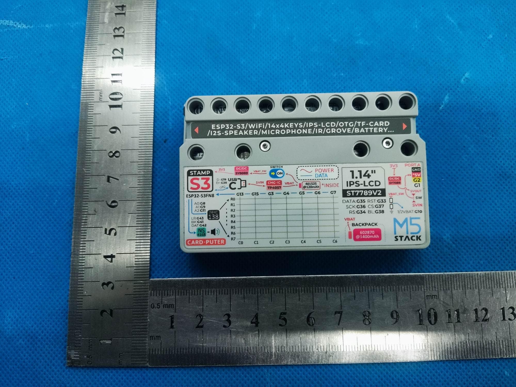
2AN3WM5CARDPUTER
Jul 21, 2024M5Cardputer
Equipment Class
DTS - Digital Transmission System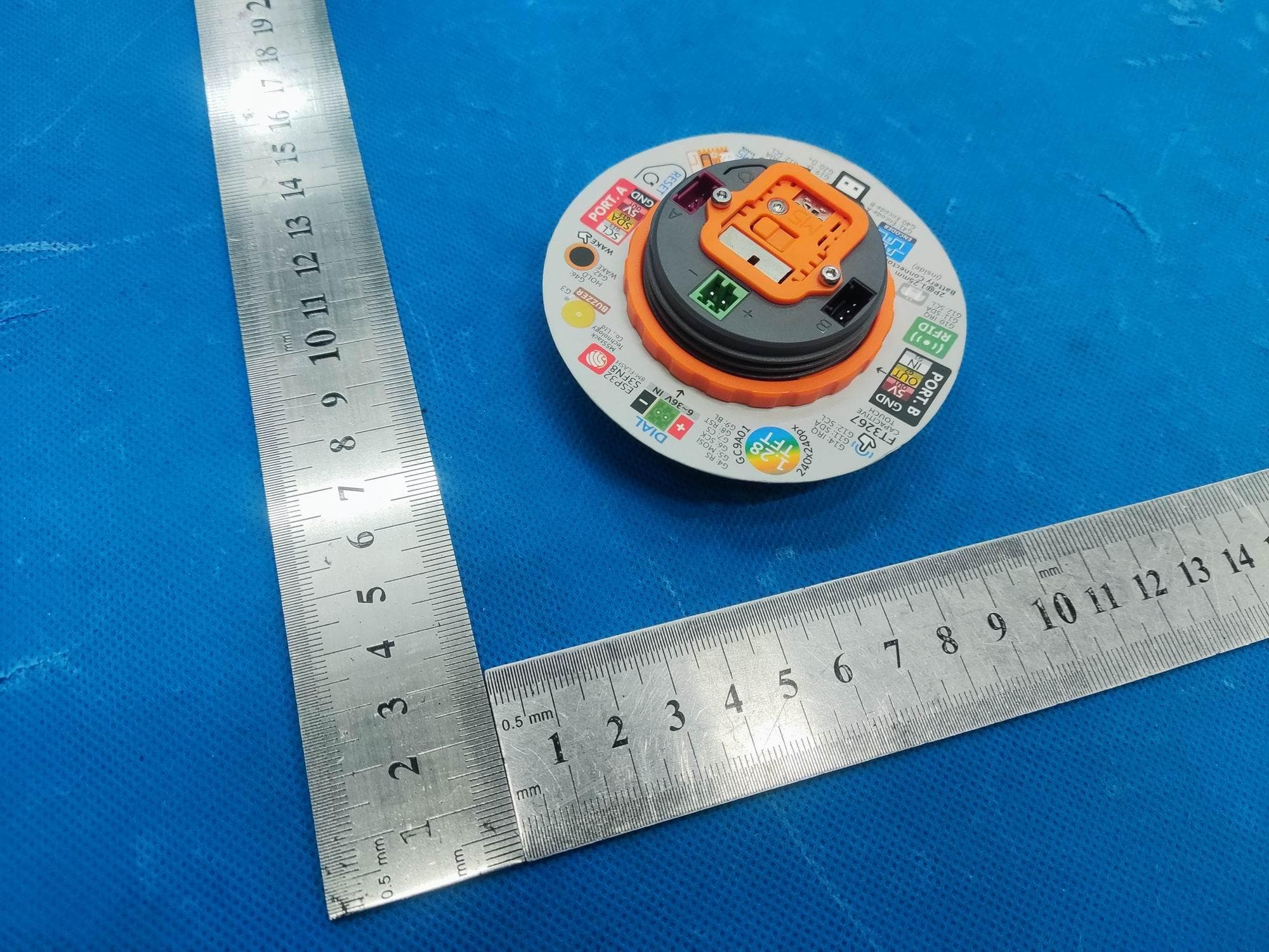
2AN3WM5DIAL
Jul 21, 2024M5Dial
Equipment Class
DTS - Digital Transmission System