2AN3WSTICKCPLUSV11M5StickC PLUS2
M5Stack Technology Co.,LtdApplication Details
- Equipment Class
- DTS - Digital Transmission System
- Date of Grant
- Jul 09, 2023
- Application Purpose
- Original Equipment
- Date of Application
- Jul 09, 2023
- Equipment Note
- M5StickC PLUS2
- Frequency Range
- 2402.00000000 - 2480.00000000
- Company
- M5Stack Technology Co.,Ltd
- Country
- China
Documents & Files
Document Text
Text extracted from the exhibit documents filed with the FCC. Open a document above to read the original.
Users Manual
M5STICKC Lite 2023 V0.01 User Manual 1. OUTLINE StickC PLUS is ESP32 board which based on ESP32-PICO-V3 module, with one LED and one button The board is made of PC+ABC. 1.1 Hardware Composition The hardware of M5StickC PLUS: ESP32-PICO-V3 module, TFT screen, IMU, IR transmitter, Red LED, Button, GROVE interface, TypeC-to -USB interface, Power Management chip and battery. StickT Add infrared camera. The product is connected to the computer, developed and used in the Desktop environment, and will contact people physically. ESP32-PICO-V3 is a System-in-Package (SiP) module that is based on ESP32, providing complete Wi-Fi and Bluetooth functionalities. The module integrates a 4-MB SPI flash. ESP32-PICO-V3 integrates all peripheral components seamlessly, including a crystal oscillator, flash, filter capacitors and RF matching links in one single package. TFT Screen is a 1.14-inch color screen driven by Sitronix's ST7789 with a resolution of 135 x 240. Operating voltage range is 2.5~3.3V IMU The MPU-6886 is a 6-axis MotionTracking device that combines a 3-axis gyroscope and a 3-axis accelerometer in a small 3 mm x 3 mm x 0.75 mm 24-pin LGA package. M5StickC Lite equips ESP32 with everything needed for programming, everything needed for operation and development 2. PIN DESCRIPTION 2.1. USB INTERFACE M5CAMREA Configuration Type-C type USB interface, support USB2.0 standard communication protocol. 2.2. GROVE INTERFACE 4p disposed pitch of 2.0mm M5CAMREA GROVE interfaces, internal wiring and GND, 5V, GPIO32, GPIO33 connected. 3. FUNCTIONAL DESCRIPTION This chapter describes the ESP32-PICO-V3 various modules and functions. 3.1. CPU AND MEMORY ESP32-PICO-V3 contains two low-power Xtensa ® 32-bit LX6 MCU. On-chip memory comprising: 448-KB of ROM, and the program starts for the kernel function calls For a 520 KB instruction and data storage chip SRAM (including flash memory 8 KB RTC) RTC flash memory of 8 KB SRAM, when the RTC can be started in Deep-sleep mode, and for storing data accessed by the main CPU RTC slow memory, of 8 KB SRAM, can be accessed by the coprocessor in Deep- sleep mode Of 1 kbit of eFuse, which is a 256 bit system-specific (MAC address and a chip set); the remaining 768 bit reserved for user program, these Flash program include encryption and chip ID 3.2. STORAGE DESCRIPTION 3.2.1. External Flash and SRAM ESP32 support multiple external QSPI flash and static random access memory (SRAM), having a hardware-based AES encryption to protect the user programs and data. ESP32 access external QSPI Flash and SRAM by caching. Up to 16 MB external Flash code space is mapped into the CPU, supports 8-bit, 16-bit and 32-bit access, and can execute code. Up to 8 MB external Flash and SRAM mapped to the CPU data space, support for 8-bit, 16-bit and 32-bit access. Flash supports only read operations, SRAM supports read and write operations. ESP32-PICO-V3 4 MB of integrated SPI Flash, the code can be mapped into CPU space, support for 8-bit, 16-bit and 32-bit access, and can execute code. Pin GPIO6 ESP32 of, GPIO7, GPIO8, GPIO9, GPIO10 and GPIO11 for connecting module integrated SPI Flash, not recommended for other functions. 3.3. CRYSTAL •ESP32-PICO-V3 integrates a 40 MHz crystal oscillator. 3.4. RTC MANAGEMENT AND LOW POWER CONSUMPTION ESP32 uses advanced power management techniques may be switched between different power saving modes. (See Table 5). •Power saving mode - Active Mode: RF chip is operating. Chip may receive and transmit a sounding signal. - Modem-sleep mode: CPU can run, the clock may be configured. Wi-Fi / Bluetooth baseband and RF - Light-sleep mode: CPU suspended. RTC and memory and peripherals ULP coprocessor operation. Any wake-up event (MAC, host, RTC timer or external interrupt) will wake up the chip. - Deep-sleep mode: only the RTC memory and peripherals in a working state. Wi- Fi and Bluetooth connectivity data stored in the RTC. ULP coprocessor can work. - Hibernation Mode: 8 MHz oscillator and a built-in coprocessor ULP are disabled. RTC memory to restore the power supply is cut off. Only one RTC clock timer located on the slow clock and some RTC GPIO at work. RTC RTC clock or timer can wake up from the GPIO Hibernation mode. •Deep-sleep mode - related sleep mode: power save mode switching between Active, Modem-sleep, Light-sleep mode. CPU, Wi-Fi, Bluetooth, and radio preset time interval to be awakened, to ensure connection Wi-Fi / Bluetooth. - Ultra Low-power sensor monitoring methods: the main system is Deep-sleep mode, ULP coprocessor is periodically opened or closed to measure sensor data. The sensor measures data, ULP coprocessor decide whether to wake up the main system. Functions in different power consumption modes: TABLE 5 Arduino IDE Development USB Driver Before the program is burned, M5Core host (including BASIC / GRAY / M5GO / FIRE / FACES) users please download the corresponding CP210X driver package according to the operating system you are using, click the button below. After decompressing the compressed package, select the installation package corresponding to the operating system value for installation. Note: M5StickC / M5StickT / ATOM Matrix / ATOM Lite support can be used without driver, users can skip this driver installation step. *Download CP2104 driver Arduino-IDE For Mac OS, make sure System preferences -> Security & Privacy -> General before installing, and allow the apps to be installed from the App Store and identified developers M5Stack Docs Product List Platform|API Cases FAQLanguage Boards Manager 1.Open up Arduino IDE, navigate to File->Peferences->Settings 2.Copy the following ESP32 Boards Manager url to Additional Boards Manager URLs: https://dl.espressif.com/dl/package_esp32_index.json M5Stack Docs Product List Platform|API Cases FAQLanguage 3.Navigate to Tools->Board:->Boards Manager... 4.Search ESP32 in the pop-up window, find it and click Install M5Stack Docs Product List Platform|API Cases FAQLanguage 5.select Tools-…
Text truncated - open the document above for the full version.
External Photos
EXHIBIT B - EUT EXTERNAL PHOTOGRAPHS port
Internal Photos
EXHIBIT C - EUT INTERNAL PHOTOGRAPHS Uncover Battery Chip Antenna
RF Exposure Info
China Certification ICT Co., Ltd (Dongguan) Report No.: CR230316126-00A Page 42 of 42 5. RF EXPOSURE EVALUATION 5.1 Applicable Standard According to§15.247(i) and §1.1310, systems operating under the provisions of this section shall be operated in a manner that ensure that the public is not exposed to radio frequency energy level in excess of the Commission’s guideline. According to KDB447498 D01 General RF Exposure Guidance v06: The 1-g and 10-g SAR test exclusion thresholds for 100 MHz to 6 GHz at test separation distances ≤ 50 mm are determined by: [(max. power of channel, including tune-up tolerance, mW)/(min. test separation distance, mm)] · [√f(GHz)] ≤ 3.0 for 1-g SAR and ≤ 7.5 for 10-g extremity SAR, where • f(GHz) is the RF channel transmit frequency in GHz • Power and distance are rounded to the nearest mW and mm before calculation • The result is rounded to one decimal place for comparison • 3.0 and 7.5 are referred to as the numeric thresholds in the step 2 below The test exclusions are applicable only when the minimum test separation distance is ≤ 50 mm and for transmission frequencies between 100 MHz and 6 GHz. When the minimum test separation distance is < 5 mm, a distance of 5 mm according to 5) in section 4.1 is applied to determine SAR test exclusion. 5.2 Measurement Result Radio Frequency (MHz) Conducted Output Power Including Tolerance Distance (mm) Calculated value Threshold (1-g) SAR Test Exclusion (dBm) (mW) BDR/EDR 2402-2480 9.6 9.12 5 2.9 3 Yes BLE 2402-2480 9 7.94 5 2.5 3 Yes WiFi 2412-2462 9.6 9.12 5 2.9 3 Yes Note: 1. The Bluetooth and WiFi can`t transmit simultenuously. 2. The Maximum Conducted Power including Tune-up Tolerance was declared by manufacturer. Result: Compliant. The stand-alone SAR test is not necessary. ===== END OF REPORT ====
RF Exposure Info
China Certification ICT Co., Ltd (Dongguan) Report No.: CR230316126-00C Page 59 of 59 5. RF EXPOSURE EVALUATION 5.1 Applicable Standard According to§15.247(i) and §1.1310, systems operating under the provisions of this section shall be operated in a manner that ensure that the public is not exposed to radio frequency energy level in excess of the Commission’s guideline. According to KDB447498 D01 General RF Exposure Guidance v06: The 1-g and 10-g SAR test exclusion thresholds for 100 MHz to 6 GHz at test separation distances ≤ 50 mm are determined by: [(max. power of channel, including tune-up tolerance, mW)/(min. test separation distance, mm)] · [√f(GHz)] ≤ 3.0 for 1-g SAR and ≤ 7.5 for 10-g extremity SAR, where • f(GHz) is the RF channel transmit frequency in GHz • Power and distance are rounded to the nearest mW and mm before calculation • The result is rounded to one decimal place for comparison • 3.0 and 7.5 are referred to as the numeric thresholds in the step 2 below The test exclusions are applicable only when the minimum test separation distance is ≤ 50 mm and for transmission frequencies between 100 MHz and 6 GHz. When the minimum test separation distance is < 5 mm, a distance of 5 mm according to 5) in section 4.1 is applied to determine SAR test exclusion. 5.2 Measurement Result Radio Frequency (MHz) Conducted Output Power Including Tolerance Distance (mm) Calculated value Threshold (1-g) SAR Test Exclusion (dBm) (mW) BDR/EDR 2402-2480 9.6 9.12 5 2.9 3 Yes BLE 2402-2480 9 7.94 5 2.5 3 Yes WiFi 2412-2462 9.6 9.12 5 2.9 3 Yes Note: 1. The Bluetooth and WiFi can`t transmit simultenuously. 2. The Maximum Conducted Power including Tune-up Tolerance was declared by manufacturer. Result: Compliant. The stand-alone SAR test is not necessary. ===== END OF REPORT ====
Test Report
TEST REPORT Applicant: M5Stack Technology Co.,Ltd Address: 5F, Tangwei Stock Commercial Building Youli Road, Bao'an District,Shenzhen, Guangdong,China FCC ID: 2AN3WSTICKCPLUSV11 Product Name: M5StickC PLUS2 Standard(s): 47 CFR Part 15, Subpart C(15.247) ANSI C63.10-2013 KDB 558074 D01 15.247 Meas Guidance v05r02 The above equipment has been tested and found compliant with the requirement of the relative standards by China Certification ICT Co., Ltd (Dongguan) Report Number: CR230316126-00A Date Of Issue: 2023/7/6 Reviewed By: Sun Zhong Title: Manager Test Laboratory: China Certification ICT Co., Ltd (Dongguan) No. 113, Pingkang Road, Dalang Town, Dongguan, Guangdong, China Tel: +86-769-82016888 China Certification ICT Co., Ltd (Dongguan) Report No.: CR230316126-00A Page 2 of 42 Test Facility The Test site used by China Certification ICT Co., Ltd (Dongguan) to collect test data is located on the No. 113, Pingkang Road, Dalang Town, Dongguan, Guangdong, China. The lab has been recognized as the FCC accredited lab under the KDB 974614 D01 and is listed in the FCC Public Access Link (PAL) database, FCC Registration No. : 442868, the FCC Designation No. : CN1314. The lab has been recognized by Innovation, Science and Economic Development Canada to test to Canadian radio equipment requirements, the CAB identifier: CN0123. Declarations China Certification ICT Co., Ltd (Dongguan) is not responsible for the authenticity of any test data provided by the applicant. Data included from the applicant that may affect test results are marked with a triangle symbol “▲”. Customer model name, addresses, names, trademarks etc. are not considered data. Unless otherwise stated the results shown in this test report refer only to the sample(s) tested. This report cannot be reproduced except in full, without prior written approval of the Company. This report is valid only with a valid digital signature. The digital signature may be available only under the Adobe software above version 7.0. This report may contain data that are not covered by the accreditation scope and shall be marked with an asterisk “★”. China Certification ICT Co., Ltd (Dongguan) Report No.: CR230316126-00A Page 3 of 42 CONTENTS T EST FACILITY .......................................................................................................................................... 2 DECLARATIONS .......................................................................................................................................... 2 DOCUMENT REVISION HISTORY .......................................................................................... 5 1. GENERAL INFORMATION .................................................................................................... 6 1.1 PRODUCT DESCRIPTION FOR EQUIPMENT UNDER TEST (EUT) ....................................................... 6 1.2 DESCRIPTION OF TEST CONFIGURATION ........................................................................................... 7 1.2.1 EUT Operation Condition: ............................................................................................................................. 7 1.2.2 Support Equipment List and Details .............................................................................................................. 7 1.2.3 Support Cable List and Details ...................................................................................................................... 7 1.2.4 Block Diagram of Test Setup ......................................................................................................................... 8 1.3 MEASUREMENT UNCERTAINTY .......................................................................................................... 9 2. SUMMARY OF TEST RESULTS .......................................................................................... 10 3. REQUIREMENTS AND TEST PROCEDURES .................................................................. 11 3.1 AC LINE CONDUCTED EMISSIONS .................................................................................................... 11 3.1.1 Applicable Standard ..................................................................................................................................... 11 3.1.2 EUT Setup.................................................................................................................................................... 12 3.1.3 EMI Test Receiver Setup ............................................................................................................................. 12 3.1.4 Test Procedure ............................................................................................................................................. 13 3.1.5 Corrected Amplitude & Margin Calculation ................................................................................................ 13 3.2 RADIATION SPURIOUS EMISSIONS .................................................................................................... 14 3.2.1 Applicable Standard ..................................................................................................................................... 14 3.2.2 EUT Setup.................................................................................................................................................... 14 3.2.3 EMI Test Receiver & Spectrum Analyzer Setup ......................................................................................... 15 3.2.4 Test Procedure ............................................................................................................................................. 15 3.2.5 Corrected Amplitude & Margin Calculation ................................................................................................ 15 3.3 6 DB EMISSION BANDWIDTH: ........................................................................................................…
Text truncated - open the document above for the full version.
Test Report
TEST REPORT Applicant: M5Stack Technology Co.,Ltd Address: 5F, Tangwei Stock Commercial Building Youli Road, Bao'an District,Shenzhen, Guangdong,China FCC ID: 2AN3WSTICKCPLUSV11 Product Name: M5StickC PLUS2 Standard(s): 47 CFR Part 15, Subpart C(15.247) ANSI C63.10-2013 KDB 558074 D01 15.247 Meas Guidance v05r02 The above equipment has been tested and found compliant with the requirement of the relative standards by China Certification ICT Co., Ltd (Dongguan) Report Number: CR230316126-00C Date Of Issue: 2023/7/6 Reviewed By: Sun Zhong Title: Manager Test Laboratory: China Certification ICT Co., Ltd (Dongguan) No. 113, Pingkang Road, Dalang Town, Dongguan, Guangdong, China Tel: +86-769-82016888 China Certification ICT Co., Ltd (Dongguan) Report No.: CR230316126-00C Page 2 of 59 Test Facility The Test site used by China Certification ICT Co., Ltd (Dongguan) to collect test data is located on the No. 113, Pingkang Road, Dalang Town, Dongguan, Guangdong, China. The lab has been recognized as the FCC accredited lab under the KDB 974614 D01 and is listed in the FCC Public Access Link (PAL) database, FCC Registration No. : 442868, the FCC Designation No. : CN1314. The lab has been recognized by Innovation, Science and Economic Development Canada to test to Canadian radio equipment requirements, the CAB identifier: CN0123. Declarations China Certification ICT Co., Ltd (Dongguan) is not responsible for the authenticity of any test data provided by the applicant. Data included from the applicant that may affect test results are marked with a triangle symbol “▲”. Customer model name, addresses, names, trademarks etc. are not considered data. Unless otherwise stated the results shown in this test report refer only to the sample(s) tested. This report cannot be reproduced except in full, without prior written approval of the Company. This report is valid only with a valid digital signature. The digital signature may be available only under the Adobe software above version 7.0. This report may contain data that are not covered by the accreditation scope and shall be marked with an asterisk “★”. China Certification ICT Co., Ltd (Dongguan) Report No.: CR230316126-00C Page 3 of 59 CONTENTS T EST FACILITY .......................................................................................................................................... 2 DECLARATIONS .......................................................................................................................................... 2 DOCUMENT REVISION HISTORY .......................................................................................... 5 1. GENERAL INFORMATION .................................................................................................... 6 1.1 PRODUCT DESCRIPTION FOR EQUIPMENT UNDER TEST (EUT) ....................................................... 6 1.2 DESCRIPTION OF TEST CONFIGURATION ........................................................................................... 8 1.2.1 EUT Operation Condition: ............................................................................................................................. 8 1.2.2 Support Equipment List and Details .............................................................................................................. 8 1.2.3 Support Cable List and Details ...................................................................................................................... 8 1.2.4 Block Diagram of Test Setup ......................................................................................................................... 9 1.3 MEASUREMENT UNCERTAINTY ........................................................................................................ 10 2. SUMMARY OF TEST RESULTS .......................................................................................... 11 3. REQUIREMENTS AND TEST PROCEDURES .................................................................. 12 3.1 AC LINE CONDUCTED EMISSIONS .................................................................................................... 12 3.1.1 Applicable Standard ..................................................................................................................................... 12 3.1.2 EUT Setup.................................................................................................................................................... 13 3.1.3 EMI Test Receiver Setup ............................................................................................................................. 13 3.1.4 Test Procedure ............................................................................................................................................. 14 3.1.5 Corrected Amplitude & Margin Calculation ................................................................................................ 14 3.2 RADIATION SPURIOUS EMISSIONS .................................................................................................... 15 3.2.1 Applicable Standard ..................................................................................................................................... 15 3.2.2 EUT Setup.................................................................................................................................................... 15 3.2.3 EMI Test Receiver & Spectrum Analyzer Setup ......................................................................................... 16 3.2.4 Test Procedure ............................................................................................................................................. 16 3.2.5 Corrected Amplitude & Margin Calculation ................................................................................................ 16 3.3 6 DB EMISSION BANDWIDTH: .........................................................................................................…
Text truncated - open the document above for the full version.
Test Setup Photos
EXHIBIT D - TEST SETUP PHOTOGRAPHS Conducted Emissions Front View Conducted Emissions Side View Radiated Emission Below 1GHz View Radiated Emission Below 1GHz View Radiated Emission Above 1GHz View Radiated Emission Above 1GHz View
Contact Information
Applicant
Jimmy Lai
Test Firm
CHINA CERTIFICATION ICT CO., LTD (DONGGUAN)Tanie Ou
[email protected]0086 0769 86858888
Technical Specifications
| # | Rule Parts | Frequency Range | Power Output |
|---|---|---|---|
| 2 | 15C | 2.40 GHz - 2.48 GHz | 7.00 mW |
Other Applications from M5Stack Technology Co.,Ltd
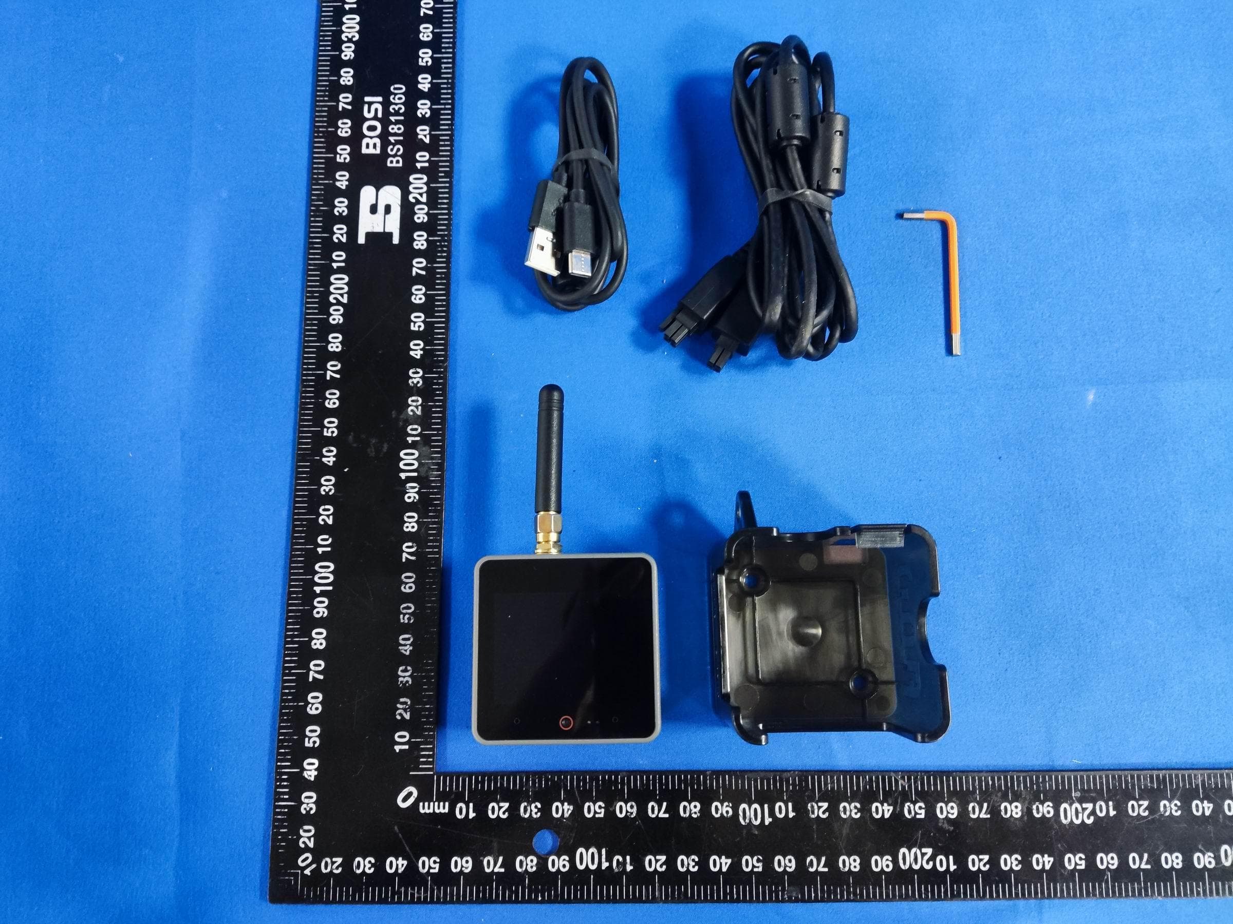
2AN3WM5FGV4
Sep 29, 2024Flow Gateway v4
Equipment Class
DTS - Digital Transmission System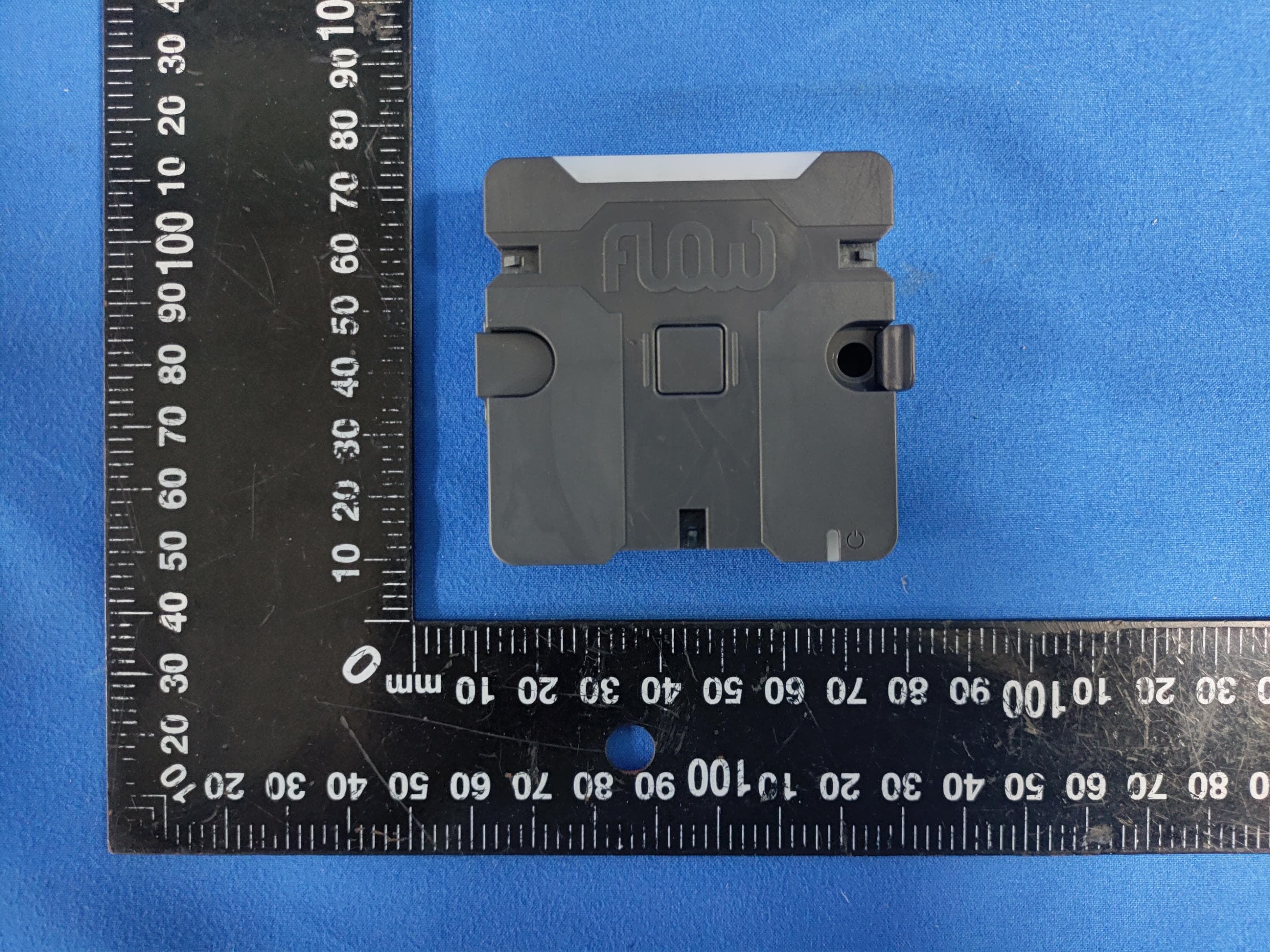
2AN3WM5FCV1
Sep 17, 2024Flow Connect
Equipment Class
DTS - Digital Transmission System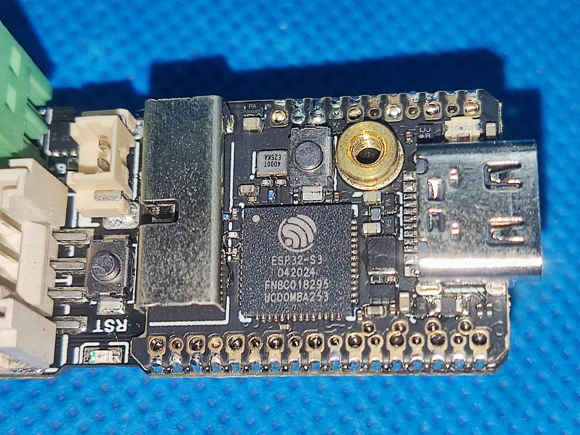
2AN3WM5DINMETER
Jul 22, 2024M5DinMeter
Equipment Class
DTS - Digital Transmission System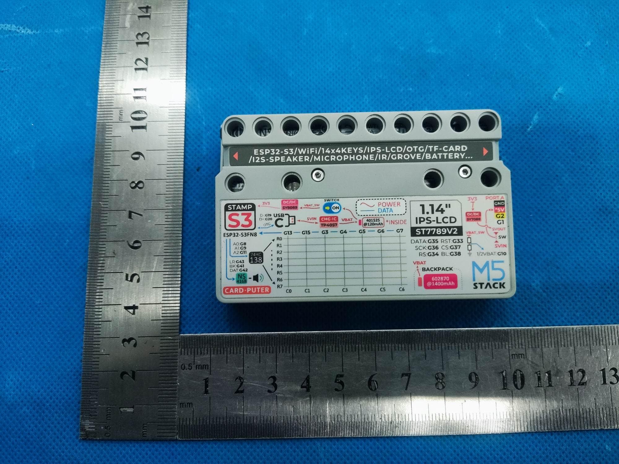
2AN3WM5CARDPUTER
Jul 21, 2024M5Cardputer
Equipment Class
DTS - Digital Transmission System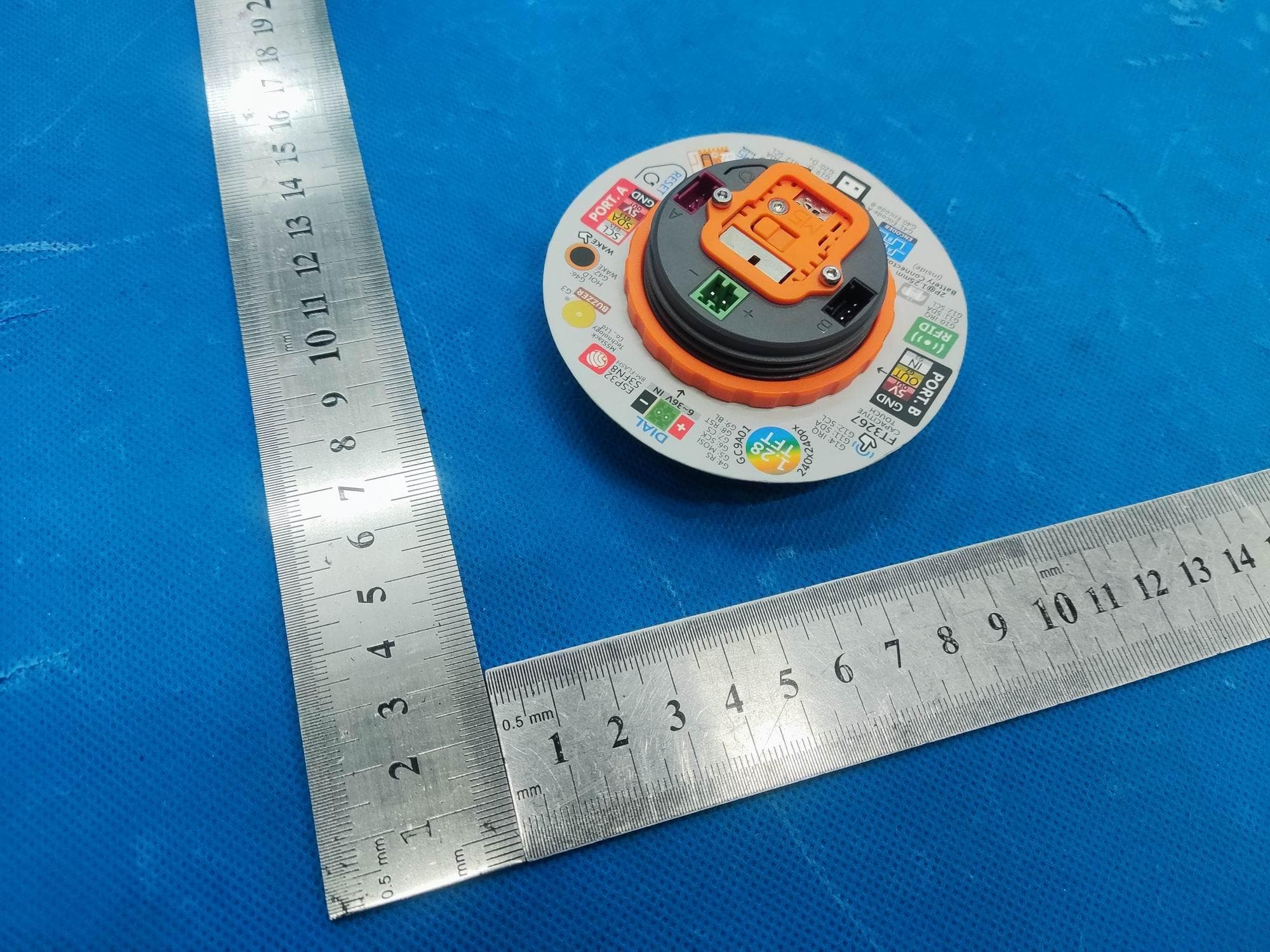
2AN3WM5DIAL
Jul 21, 2024M5Dial
Equipment Class
DTS - Digital Transmission System