2AN5RFSV2480Shark Byte TX5S.1
SHENZHEN FATSHARK ELECTRONIC CO., LTD
Click to zoom
Application Details
- Equipment Class
- NII - Unlicensed National Information Infrastructure TX
- Date of Grant
- Jan 24, 2021
- Application Purpose
- Original Equipment
- Date of Application
- Jan 24, 2021
- Equipment Note
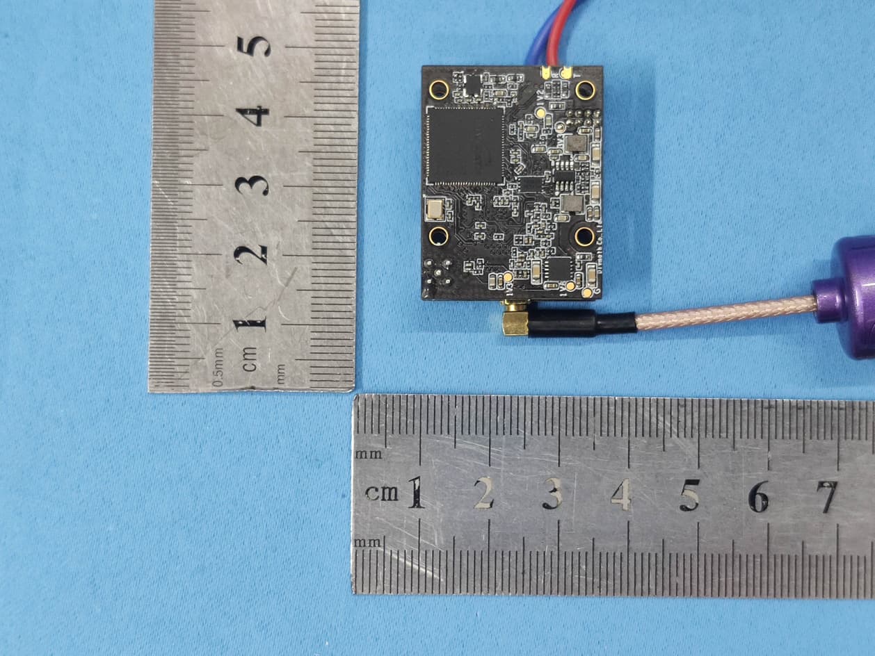
- Shark Byte TX5S.1
- Frequency Range
- 5770.00000000 - 5805.00000000
- Country
- China
Documents & Files
Document Text
Text extracted from the exhibit documents filed with the FCC. Open a document above to read the original.
Users Manual
Shark Byte Contents TX5M.1 Specifications ..................................................................................................................................5 Shark Byte Video Transmitter TX5S.1 .....................................................................................................6 TX5S.1 Connection Diagram ......................................................................................................................6 TX5S.1 Specifications ..................................................................................................................................7 Adjusting VTX and Camera Parameters with the Keypad ...............................................................7 Shark Byte 5 9 8 1 2 6 7 3 10 GND TX RX 7–26V 1Power/UART cable 2FW Update Connector 3UART (3.3V) 4MIPI Connector 5Power IN (7-26V) 6Power LED (red) 7u.FL Antenna Connector 8Status LED (blue) 9330 μF Capacitor 10Key Pad Connector Runcam Nano HD 1MIPI Camera 2MIPI cable 1 2 ! RC Transmitter RC Receiver Camera Flight Controller Video Transmitter VTX Antenna (u.FL) Battery Connector Capacitor SBUS/IBUS/UART MIPI TX RX GND 7–26V RX TX 50v 330 μF TX5S.1 CONNECTION DIAGRAM Refer to the diagram below to mount and connect the air unit to your chosen airframe. Shark Byte Video Transmitter TX5S.1 The Shark Byte TX5S.1 is a digital HD 720p 60fps short range video transmitter capable of delivering up to 200mw on 5.8GHz. The TX5S.1 works with the Shark Byte RX5.1 goggle module to transmit video, and a remote controller to control the parameters for transmitter and camera wirelessly. The Shark Byte TX5S.1 consists of a Runcam Nano HD camera and a video transmitter (VTX) made up of a single PCBs. Power input range is 7V – 26V (2S – 6S). A large capacitor (220+μF) is required to be mounted in parallel with the power input connector to avoid voltage spikes (and subsequent damage) to the VTX. DO NOT power the VTX without a capacitor on the power input. DO NOT power ON the VTX without an appropriate 5.8GHz antenna connected to the u.FL connector. If you power ON the VTX without an antenna connected, it may result in permanent damage. DO NOT touch the video transmitter during or immediately after operation, wait for it to cool down. It is normal for the VTX to become hot during or after operation. DO NOT use the VTX for an extended period when the temperature is high or if there is poor ventilation. If the VTX does not get adequate airflow for cooling during operation, it may overheat and enter overheat protection mode, which will reduce range performance. Shark Byte CHFCC (MHz)CE (MHz) 156605735 256955770 357355805 457705839 55805NA 65839NA 75878NA 85914NA TX5S.1 SPECIFICATIONS Weight: 10.3g including camera and cable (without antenna), 5.2g for VTX only Dimensions: Camera: 14 x 14mm with 19 x 19 adaptor VTX: 32.5 x 32.5 x 5 mm Coaxial cable: 85mm Mounting Pattern: VTX: 20 x 20mm, M2 Operating Frequencies: Transmitting Power/ Power Consumption: 25mW: 5.1W 200mW: 6.7W IO Interface: u.FL UART: 3.3V Update Port: 7-pin SH 1.0 Supported Flight Control System: BetaFlight: 4.1 or above (MultiWii API version 1.41) iNav 2.3 or above Input Power: 7-26V Operating temperature: 32°-104°F (0°-40°C) Adjusting VTX and Camera Parameters with the Keypad The VTX or Camera parameters can also be set with the attached keypad. Camera: The 5-way joystick button (1) is used exclusively for camera settings. Settings and options are displayed on-screen on the live video for this configuration mode. • Press Middle: Enter • Press Up: Up • Press Down: Down • Press Left: Left • Press Right: Right VTX: The select button (2) and 7 segment LED display (3) are used exclusively for setting VTX parameters. To change channel: • Short press the select button (2), the 7 segment LED display (3) will show the current channel number (1-8), another short press will cause it will change to next channel. If no changes are made after 15 seconds, the 7 segment LED display (3) will turn off and the setting will be saved. To change power level: • Press and hold the select button (2) for 3 seconds, the 7 segment LED display (3) will blink ‘P’ then show current power level (1.=25mW, 2.=200mW,3.=500mW). To make a change, short press the select button (2) to cycle to the next power level. If no changes are made after 15 seconds, the 7 segment LED display (3) will turn off and the setting will be saved. To select Low Power (LP) mode: • Press and hold the select button (2) for 10 seconds, the 7 segment LED display (3) will blink ‘P’ then ‘L’, show “O” (ON) or ‘F’ (OFF). If no changes are made after 15 seconds, the 7 segment LED display (3) will turn off and the setting will be saved. 3 1 2 15-way joystick button for Camera 2Select Button for VTX 37 Segment LED Display for VTX TX5M.1 Keypad ConnectionTX5S.1 Keypad Connection Shark Byte FCC Statement This equipment has been tested and found to comply with the limits for a Class B digital device, pursuant to Part 15 of the FCC Rules. These limits are designed to provide reasonable protection against harmful interference in a residential installation. This equipment generates uses and can radiate radio frequency energy and, if not installed and used in accordance with the instructions, may cause harmful interference to radio communications. However, there is no guarantee that interference will not occur in a particular installation. If this equipment does cause harmful interference to radio or television reception, which can be determined by turning the equipment off and on, the user is encouraged to try to correct the interference by one or more of the following measures: -- Reorient or relocate the receiving antenna. -- Increase the separation between the equipment and receiver. -- Connect the equipment into an outlet on a circuit different from that to which the receiver is connected. -- Consult the dealer or an experienced radio/TV technician for help. Changes or modifications not expressly app…
Text truncated - open the document above for the full version.
Cover Letter(s)
Agent Authorization Letter Company: SHENZHEN FATSHARK ELECTRONIC CO., LTD Address: 2/F,Bldg8,Block1,Guangyayuan Industrial Zone, Guangyayuan Road, Wuhe Community,Bantian Longgang, shenzhen, China Product Name: Shark Byte TX5S.1 Model Number(s): FSV2480 Product Description: Shark Byte TX5S.1 We authorize MiCOM Labs Inc., 575 Boulder Court, Pleasanton, California 94566, USA, to act on our behalf on all matters concerning the certification of above named equipment. We declare that MiCOM Labs Inc. is allowed to forward all information related to the approval and certification of equipment to the regulatory agencies as required and to discuss any issues concerning the approval application. Any and all acts carried out by MiCOM Labs on our behalf shall have the same effect as acts of our own. Signature: Date: 2020-12-24 Name: Linda Lee Title: Purchasing supervisor Company: SHENZHEN FATSHARK ELECTRONIC CO., LTD
Cover Letter(s)
SHENZHEN FATSHARK ELECTRONIC CO., LTD Office of Engineering Technology Federal Communications Commission 7435 Oakland Mills Road Columbia, MD 21046 USA Date: 2020-12-24 Subject; Request for Confidentiality FCC ID: 2AN5RFSV2480 To Whom It May Concern, Pursuant to the provisions of the Commission’s rules Title 47 Sections §0.457 and §0.459, we are requesting the Commission to withhold the following attachment(s) as confidential documents from public disclosure indefinitely. These documents contain detailed system and equipment descriptions and are considered as proprietary information in operation of the equipment. The public disclosure of these documents might be harmful to our company and would give competitors an unfair advantage in the market. Schematic Diagram Block Diagram Operational Description FCC Software Security Requirements for UNII devices It is our understanding that all measurement test reports, FCC ID label format and correspondence during the certification review process cannot be granted as confidential documents and this information will be available for public review once the grant of equipment authorization is issued. Sincerely, Signature: Name: linda Lee Title: Purchasing supervisor
Cover Letter(s)
FCC Software Configuration Control Declaration SHENZHEN FATSHARK ELECTRONIC CO., LTD FCC Software Configuration Control Declaration Federal Communications Commission Authorization and Evaluation Division 7435 Oakland Mills Road Columbia, MD 21046 Attn: OET Dept. Product/ Model Number: Shark Byte TX5S.1/ FSV2480 Regarding FCC Country Code Selection guidelines identified in KDB 594280 D01 V02r01. “All applications for equipment authorization for transmitters that can have radio parameters, or other technical parameters, reported to the Commission set by software must have an attestation indicating that no third party will have software, or configuration control, to program the device out of compliance of the technical rules under which it has been certified.” We declare that no third party will have software, or configuration control, to program the device out of compliance of the technical rules under which it has been certified. Name: Linda Lee Date: 2020/12/24 Title: Purchasing supervisor Signature of applicant:
RF Exposure Info
FCC ID: 2AN5RFSV2480 RF Exposure Evaluation Limits The criteria listed in the following table shall be used to evaluate the environment impact of human exposure to radio frequency (RF) radiation as specified in 1.1307(b) Limits for Maximum Permissible Exposure (MPE) Frequency range (MHz) Electric field strength (V/m) Magnetic field strength (A/m) Power density (mW/cm 2 ) Averaging time (minutes) (A) Limits for Occupational/Controlled Exposures 0.3–3.0 614 1.63 *(100) 6 3.0–30 1842/f 4.89/f *(900/f 2 ) 6 30–300 61.4 0.163 1.0 6 300–1500 f/300 6 1500–100,000 5 6 (B) Limits for General Population/Uncontrolled Exposure 0.3–1.34 614 1.63 *(100) 30 1.34–30 824/f 2.19/f *(180/f 2 ) 30 30–300 27.5 0.073 0.2 30 300–1500 f/1500 30 1500–100,000 1.0 30 f = frequency in MHz Friis transmission formula: Pd = (Pout*G)/(4*pi*r 2 ) Where Pd = power density in mW/cm 2 , Pout = output power to antenna in mW; G = gain of antenna in linear scale, Pi = 3.1416; R = distance between observation point and center of the radiator in cm Pd id the limit of MPE, 1 mW/cm 2 . If we know the maximum gain of the antenna and the total power input to the antenna, through the calculation, we will know the distance r where the MPE limit is reached. Test Procedure Software provided by client enabled the EUT to transmit and receive data at lowest and highest channel individually. FCC ID: 2AN5RFSV2480 Test Result of RF Exposure Evaluation Channel Output power to antenna (mW) Power Density at R=20cm (mW/cm 2 ) Limit (mW/cm 2 ) Result 5770MHz 14.76 0.00523 1.0 PASS 5805MHz 17.70 0.00627 1.0 PASS Remark: antenna gain=2.5dBi
Test Report
Global United Technology Services Co., Ltd. Report No.: GTS202011000121F01 Authorized Signature: Robinson Lo Laboratory Manager This results shown in this test report refer only to the sample(s) tested, this test report cannot be reproduced, except in full, without prior written permission of the company. The report would be invalid without specific stamp of test institute and the signatures of compiler and approver. Page 1 of 28 TEST REPORT Applicant: SHENZHEN FATSHARK ELECTRONIC CO., LTD Address of Applicant: 2/F,Bldg8,Block1,Guangyayuan Industrial Zone, Guangyayuan Road, Wuhe Community,Bantian Longgang, shenzhen, China Manufacturer: SHENZHEN FATSHARK ELECTRONIC CO., LTD Address of Manufacturer: 2/F,Bldg8,Block1,Guangyayuan Industrial Zone, Guangyayuan Road,Wuhe Community,Bantian Longgang, shenzhen, China Equipment Under Test (EUT) Product Name: Shark Byte TX5S.1 Model No.: FSV2480 Trade Mark: FAT SHARK FCC ID: 2AN5RFSV2480 Applicable standards: FCC CFR Title 47 Part 15 Subpart E Section 15.407 Date of sample receipt: November 11, 2020 Date of Test: November 12, 2020-December 23, 2020 Date of report issued: December 24, 2020 Test Result : PASS * * In the configuration tested, the EUT complied with the standards specified above. Report No.: GTS202011000121F01 Global United Technology Services Co., Ltd. No. 123-128, Tower A, Jinyuan Business Building, No.2, Laodong Industrial Zone, Xixiang Road, Baoan District, Shenzhen, Guangdong, China Telephone: +86 (0) 755 2779 8480 Fax: +86 (0) 755 2779 8960 Page 2 of 28 2 Version Version No. Date Description 00 December 24, 2020 Original Prepared By: Date: December 24, 2020 Project Engineer Check By: Date: December 24, 2020 Reviewer Report No.: GTS202011000121F01 Global United Technology Services Co., Ltd. No. 123-128, Tower A, Jinyuan Business Building, No.2, Laodong Industrial Zone, Xixiang Road, Baoan District, Shenzhen, Guangdong, China Telephone: +86 (0) 755 2779 8480 Fax: +86 (0) 755 2779 8960 Page 3 of 28 3 Contents Page 1 COVER PAGE ........................................................................................................................................... 1 2 VERSION .................................................................................................................................................. 2 3 CONTENTS .............................................................................................................................................. 3 4 TEST SUMMARY ..................................................................................................................................... 4 4.1 MEASUREMENT UNCERTAINTY ............................................................................................................ 4 5 GENERAL INFORMATION ...................................................................................................................... 5 5.1 GENERAL DESCRIPTION OF EUT ......................................................................................................... 5 5.2 TEST MODE ........................................................................................................................................ 6 5.3 DESCRIPTION OF SUPPORT UNITS ....................................................................................................... 6 5.4 DEVIATION FROM STANDARDS ............................................................................................................. 6 5.5 ABNORMALITIES FROM STANDARD CONDITIONS ................................................................................... 6 5.6 TEST FACILITY .................................................................................................................................... 6 5.7 TEST LOCATION ................................................................................................................................. 6 5.8 ADDITIONAL INSTRUCTIONS ................................................................................................................. 6 6 TEST INSTRUMENTS LIST ..................................................................................................................... 7 7 TEST RESULTS AND MEASUREMENT DATA ...................................................................................... 9 7.1 ANTENNA REQUIREMENT ..................................................................................................................... 9 7.2 CONDUCTED EMISSIONS ................................................................................................................... 10 7.3 CONDUCTED PEAK OUTPUT POWER .................................................................................................. 13 7.4 CHANNEL BANDWIDTH ...................................................................................................................... 14 7.5 POWER SPECTRAL DENSITY ............................................................................................................. 16 7.6 BAND EDGE ...................................................................................................................................... 18 7.6.1 Radiated Emission Method ........................................................................................................ 18 7.7 SPURIOUS EMISSION ......................................................................................................................... 21 7.7.1 Radiated Emission Method ........................................................................................................ 21 7.8 FREQUENCY STABILITY ..................................................................................................................... 26 8 TEST SETUP PHOTO ............................................................................................................................ 28 9 EUT CONSTRUCTIONAL DETAILS ...........................................................................…
Text truncated - open the document above for the full version.
Test Setup Photos
Radiated Emission Conducted Emission
Contact Information
Applicant
linda Lee
Technical Contact
Test Firm
Global United Technology Services Co. Ltd.Robinson Lo
Technical Specifications
| # | Rule Parts | Frequency Range | Power Output |
|---|---|---|---|
| 1 | 15E | 5.77 GHz - 5.80 GHz | 17.70 mW |
Other Applications from SHENZHEN FATSHARK ELECTRONIC CO., LTD
2AN5RFSV2478
Jan 24, 2021Shark Byte TX5M.1
Equipment Class
NII - Unlicensed National Information Infrastructure TX