2AN9S-ABX00112Arduino Nano Matter, Arduino Nano Matter (with headers)
Arduino S.r.l.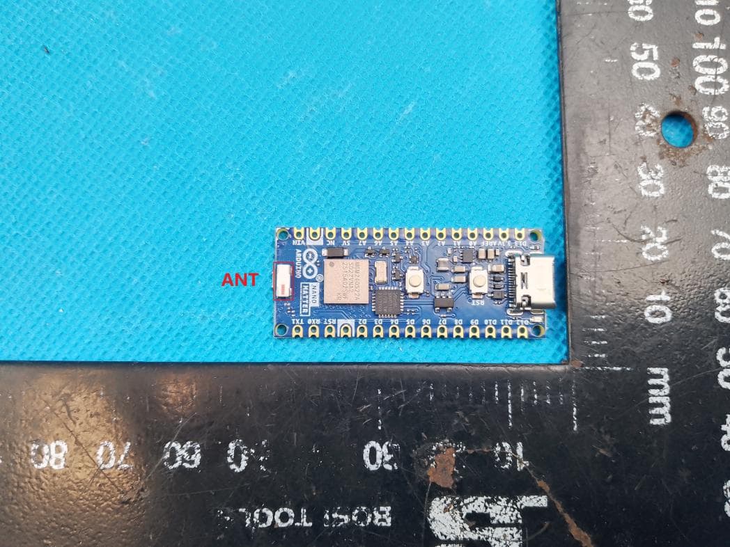
Click to zoom
Application Details
- Equipment Class
- DTS - Digital Transmission System
- Date of Grant
- Mar 19, 2026
- Application Purpose
- Original Equipment
- Equipment Note
- Arduino Nano Matter, Arduino Nano Matter (with headers)
- Frequency Range
- 2402.00000000 - 2480.00000000
- Company
- Arduino S.r.l.
- Country
- Italy
Documents & Files
Document Text
Text extracted from the exhibit documents filed with the FCC. Open a document above to read the original.
Users Manual
September, 4th 2024 Arduino Nano Matter Sales Brief 2 Table of Contents ➔Product Overview ➔Benefits ➔Technical Specs ➔A New Arduino Paradigm ➔Applications ➔Pricing ➔Related Products ➔Support 3 Product Overview Enjoy your new automated home Develop multiple homeand building automation applications with the Nano Matter. The Nano Matter merges the well-known Arduino way of making complex technology more accessible with the powerful MGM240Sfrom Silicon Labs, to bring Matter, one of the most popular IoT connectivity standards, closer to the maker and professional world. Thanks to its tiny size (18 x 45 mm) and robust design, the board is ideal for projects that need to combine low-power capabilitiesand multiple connectivity options, including BLE® and Openthread®. Start interacting with any Matter-compatible device without effort and take advantage of a wide range of peripherals and I/Osto connect any external equipment. 4 Benefits ●Quickly interact with Matter compatible devices with a user-friendly coding experience ●Take advantage of multiple connectivity options in a compact form factor, i.e. 802.15.4 Thread® and Bluetooth® Low Energy ●Great prototyping tool for scalable professional applications ●Protect your projects from threats with the embedded Secure Vault® technology, a collection of industry-leading security features ●Enable always-on data processing thanks to its low power capabilities ●Start debugging in no time leveraging the debugging over USB feature 5 Tech specs Microcontroller ●MGM240SD22VNA: ○32-bit ARM Cortex®-M33 with DSP instruction and FPU Interfaces I2C SPI UART PWM Digital I/Os ADC (up to 16 bit) DAC Memory ●1536 kB Flash ●256 kB RAM Security ●Secure Vault® High USB ●1x USB-C connector Extra ●RGB LED ●User push-buttons Connectivity ●802.15.4 Thread® ●Bluetooth® Low Energy 5.3 and Bluetooth® Mesh ●Matter-ready Smart Home Connectivity I/O Voltage ●3.3V Antenna ●On-board 2.4GHz Input Voltage (nominal) ●5V Clock Speed ●78 MHz Dimensions ●18 mm x 45 mm 6 Tech specs USB-C Connector Silicon Labs MGM240S Antenna User Push- Buttons Castellated and Headers pins for (I2C, SPI, UART,PWM, Digital I/Os That’s a wrap Thank you!
Users Manual
User Manual SKU: ABX00112-ABX00137 Description Expand your home automation and building management projects with the Arduino Nano Matter. This board integrates the high-performance MGM240S microcontroller from Silicon Labs and directly brings the advanced Matter standard for Internet of Things (IoT) connectivity to hobbyists and professionals. The Nano Matter's compact and sturdy build, measuring 18 mm x 45 mm, is perfect for projects that demand energy efficiency and diverse connectivity options, such as Bluetooth® Low Energy and OpenThread. Embrace the simplicity and versatility of the Nano Matter to effortlessly interface with any Matter® compatible devices and leverage the Arduino ecosystem's wide range of peripherals and inputs/outputs to enhance your device connectivity and project capabilities. The Nano Matter is available in two variants: without headers (SKU: ABX00112) and with pre-installed headers (SKU: ABX00137). Target Areas Internet of Things, home automation, professional automation, environmental monitoring, and climate control Arduino® Nano Matter 1 / 18Arduino® Nano MatterModified: 09/01/2026 3 4 4 5 5 6 6 6 7 7 8 9 10 10 10 10 10 10 11 11 13 14 15 15 15 15 16 16 18 18 18 CONTENTS 1 Application Examples 2 Features 2.1 General Specifications Overview 2.2 Included Accessories 2.3 Related Products 3 Ratings 3.1 Recommended Operating Conditions 3.2 Power Consumption 4 Functional Overview 4.1 Pinout 4.2 Block Diagram 4.3 Power Supply 5 Device Operation 5.1 Getting Started - IDE 5.2 Getting Started - Arduino Cloud Editor 5.3 Getting Started - Arduino Cloud 5.4 Sample Sketches 5.5 Online Resources 6 Mechanical Information 6.1 Board Dimensions 6.2 Board Connectors 6.3 Board Peripherals and Actuators 7 Product Compliance 7.1 Product Compliance Summary 7.2 Declaration of Conformity CE DoC (EU) 7.3 Declaration of Conformity to EU RoHS & REACH 211 01/19/2021 7.4 Conflict Minerals Declaration 8 FCC Caution 9 Company Information 10 Reference Documentation 11 Document Revision History Arduino® Nano Matter 2 / 18Arduino® Nano MatterModified: 09/01/2026 1 Application Examples The Arduino Nano Matter is not just an IoT board, it is a gateway to innovation in various sectors, from streamlining manufacturing processes to creating responsive and comfortable living and working environments. Discover more about the transformative potential of the Nano Matter in the following application examples: Smart homes: Transform residential spaces into intelligent environments with the Nano Matter, capable of: Voice-controlled smart home: Integrate the Nano Matter with popular voice assistant platforms like Amazon Alexa or Google Assistant, enabling residents to control smart home devices, such as lights, thermostats, and switches, using simple voice commands, enhancing convenience and accessibility. Smart lighting: Automate your home lighting system with the Nano Matter to adjust the brightness based on occupancy, time of day, or ambient light levels, saving energy and ensuring optimal lighting conditions in every room. Automated shades: Connect the Nano Matter to your motorized shades to automatically adjust them according to sunlight exposure, room occupancy, or specific times of the day, creating the perfect ambiance while improving energy efficiency. Home health monitoring: Use the Nano Matter to connect with environmental sensors, monitor indoor conditions like pressure, humidity, and temperature, and maintain a healthy living environment by providing actionable insights for comfort and well-being. Building automation: Elevate building management with the Nano Matter, enhancing comfort and efficiency through: HVAC control and monitoring: Implement the Nano Matter to connect and control HVAC systems across various building zones. Monitor environmental conditions and adjust settings for optimal indoor comfort while maximizing energy efficiency. Energy management: Use Nano Matter's connectivity to smart meters and appliances to view a building's energy consumption. Implement energy-saving measures automatically, reducing costs and environmental impact. Occupancy sensing and space utilization: With the Nano Matter and Matter-enabled sensors, gain insights into actual building occupancy and use this data to adjust lighting, heating, and cooling systems, ensuring efficient use of space and resources. Arduino® Nano Matter 3 / 18Arduino® Nano MatterModified: 09/01/2026 Industrial automation: Unlock the full potential of modern manufacturing with the Nano Matter. Designed for seamless integration into industrial settings, the Nano Matter streamlines operations through: Machine-to-Machine interoperability: Enhance your factory floor with the Nano Matter boards to enable dynamic supervision between machines. Should one machine begin producing defective parts due to a malfunction, adjacent machines are instantly alerted, halting their operations and notifying a human operator, thus reducing waste and downtime. Machine status monitoring: Integrate the Nano Matter into your industrial systems for real-time monitoring of critical conditions such as temperature, pressure, and humidity, ensuring timely maintenance and intervention, preventing costly breakdowns, and maintaining consistent production quality. Worker safety optimization: Elevate safety standards in your facility with the Nano Matter, which provides real-time monitoring of environmental conditions and detects personnel presence in hazardous areas, enhancing worker safety by preventing machine operation when a human is detected in dangerous zones. 2 Features 2.1 General Specifications Overview The Arduino Nano Matter merges the well-known Arduino way of making complex technology more accessible, bringing Matter, one of the most popular IoT connectivity standards, closer to the hobbyist and professional world. The powerful MGM240S multi-protocol wireless module from Silicon Labs is the main controller of the board. The main features are highlighted in …
Text truncated - open the document above for the full version.
RF Exposure Info
TEST REPORT For RF Expose Report No ......................................... : CHTW25110072 Project No ........................................ : SHT2511087603W FCC ID ............................................. : 2AN9S-ABX00112 Applicant’s name .............................. : Arduino S.r.l. Address ............................................ : Via Andrea Appiani, 25, 20900 MONZA (Italy) Product Name .................................. : Arduino Nano Matter, Arduino Nano Matter (with headers) Trade Mark ....................................... : Model No. ......................................... : ABX00112 Listed Model(s) ................................ : ABX00137 Standard........................................... : FCC Part 2 (Section 2.1091) Date of receipt of test sample..........: 2024/11/19 Date of testing.............................: 2024/11/16-2024/12/16,2025/11/13-2025/11/28 Date of issue...............................: 2025/12/01 Result ................... ........................: Pass Compiled by (Position+Printed name+Signature) . : File administrator Xiaodong Zhao Supervised by (Position+Printed name+Signature) . : Project Engineer Kiki Kong Approved by (Position+Printed name+Signature) . : RF Manager Xu Yang Testing Laboratory Name.............. : Shenzhen Huatongwei International Inspection Co., Ltd. Address ............................................ : Building 7, Baiwang Idea Factory, No.1051, Songbai Road, Yangguang Community, Xili Subdistrict, Nanshan District, Shenzhen, Guangdong, China Test Report Form No. ........................ : R0066 Test Report Form(s) Originator .......... : Shenzhen Huatongwei International Inspection Co., Ltd. Master TRF ........................................ : Dated 2025-07 Shenzhen Huatongwei International Inspection Co., Ltd. All rights reserved. This publication may be reproduced in whole or in part for non-commercial purposes as long as the Shenzhen Huatongwei International Inspection Co., Ltd. is acknowledged as copyright owner and source of the material. Shenzhen Huatongwei International Inspection Co., Ltd. takes no responsibility for and will not assume liability for damages resulting from the reader's interpretation of the reproduced material due to its placement and context.The test report merely correspond to the test sample.The authenticity of this Test Report and its contents can be verified by contacting the Laboratory, responsible for this Test Report. Report No.: CHTW25110072 Page 2 of 7 Contents 1. TEST STANDARDS AND REPORT VERSION 3 1.1. Test standards 3 1.2. Report version information 3 2. SUMMARY 4 2.1. Client Information 4 2.2. Product Description 4 2.3. Radio Specification Description 5 2.4. Testing Laboratory Information 5 3. RF EXPOSURE 6 4. EXTERNAL AND INTERNAL PHOTOS OF THE EUT 7 Report No.: CHTW25110072 Page 3 of 7 1. TEST STANDARDS AND REPORT VERSION 1.1. Test standards The tests were performed according to following standards: FCC Part 2 (Section 2.1091)- Radiofrequency radiation exposure evaluation: mobile devices. KDB 447498 D04 Interim General RF Exposure Guidance v01- RF Exposure Procedures and Equipment Authorization Policies for Mobile and Portable Devices FCC Part 1 (Section 1.1307)- Actions that may have a significant environmental effect, for which Environmental Assessments (EAs) must be prepared. 1.2. Report version information Revision No. Date of issue Description N/A 2025-12-01 Original Report No.: CHTW25110072 Page 4 of 7 2. SUMMARY 2.1. Client Information Applicant: Arduino S.r.l. Address: Via Andrea Appiani, 25, 20900 MONZA (Italy) Manufacturer: Arduino S.r.l. Address: Via Andrea Appiani, 25, 20900 MONZA (Italy) 2.2. Product Description Product Name: Arduino Nano Matter, Arduino Nano Matter (with headers) Trade Mark: Model No.: ABX00112 Listed Model(s): ABX00137 Power supply: DC 5V Hardware version: v 0.5 Software version: v 2.1.0 Report No.: CHTW25110072 Page 5 of 7 2.3. Radio Specification Description Bluetooth Support function: BLE 1M,BLE 2M Modulation: GFSK Operation frequency: 2402MHz~2480MHz Channel number: 40 Channel separation: 2MHz Antenna type: Ceramic Antenna Antenna gain: -1.00dBi 2.4GHz Band Modulation: GFSK Operation frequency: 2405MHz~2480MHz Channel number: 16 Channel separation: 5MHz Antenna type: Ceramic Antenna Antenna gain: -1.00dBi 2.4. Testing Laboratory Information Laboratory Name Shenzhen Huatongwei International Inspection Co., Ltd. Laboratory Location Building 7, Baiwang Idea Factory, No.1051, Songbai Road, Yangguang Community, Xili Subdistrict, Nanshan District, Shenzhen, Guangdong, China Contact information: Tel: 400-963-0755 E-mail: [email protected] http://www.szhtw.com.cn Report No.: CHTW25110072 Page 6 of 7 3. RF EXPOSURE LIMIT ◎ Single transmitter: The criteria listed in the following table shall be used to evaluate the environment impact of human exposure to radio frequency (RF) radiation as specified in 1.1307(b) Limits for Maximum Permissible Exposure (MPE) Frequency range (MHz) Electric field strength (V/m) Magnetic field strength (A/m) Power density (mW/cm 2 ) Averaging time (minutes) (A) Limits for Occupational/Controlled Exposures 0.3–3.0 614 1.63 *(100) 6 3.0–30 1842/f 4.89/f *(900/f 2 ) 6 30–300 61.4 0.163 1.0 6 300–1500 - - f/300 6 1500–100,000 - - 5 6 (B) Limits for General Population/Uncontrolled Exposure 0.3–1.34 614 1.63 *(100) 30 1.34–30 824/f 2.19/f *(180/f 2 ) 30 30–300 27.5 0.073 0.2 30 300–1500 - - f/1500 30 1500–100,000 - - 1.0 30 Note: f = frequency in MHz ◎ Simultaneous transmission: Simultaneous transmission MPE test exclusion applies when the sum of the MPE ratios for all simultaneously transmitting antennas incorporated in a host device is≤1.0. EVALUATION METHOD Transmission formula: Pd = (Pout*G)/(4*pi*r 2 ) Where Pd = power density in mW/cm 2 , Pout = output power to antenna in mW, G = gain of antenna in linear scale; Pi = 3.1416, R = distance between observation point and center of the radiator in cm TEST RESULT Passed Not Appl…
Text truncated - open the document above for the full version.
Test Setup Photos
TEST SETUP PHOTOS Radiated Emission AC Conducted Emission
Test Report
P/N: 2450AT42E010B001E Legacy P/N: 2450AT42E010B Doc# 36S0021A Page 1 of 12 / Revision 6.0 Datasheet: 2450AT42E010B001E johansontechnology.com 4001 Calle Tecate • Camarillo, CA 93012, USA • +1.805-389-1166 2024 Johanson Technology, Inc. All Rights Reserved 2.44 GHz RF Chip Antenna, Above Metal* •2.4 – 2.48 GHz operational frequency •Bluetooth, WLAN •SMD, 5.0x2.0x1.5mm (LxWxT) •Center-edge mount, circular PCB •RoHS compliant and AEC-Q200 Qualified available Johanson Technology, Inc. (JTI) miniature RF ceramic chip antennas are made using Low Temperature Co-fired Ceramic (LTCC) technology which has the ability to embed low and high dielectric constants inside our antenna. This enables our components to have high detuning resilience and stability over extreme temperatures (~2ppm). *This antenna will generally have a metal layer directly underneath for proper operation, exceptions may apply. General Specifications 1 2 Maximum Ratings 1 Typical value represents average measurement at 25°C. Min./Max. values represent measurements over specified operating temperature. 2 General specifications measured on Johanson’s evaluation board P/N 2450AT42E010B001CE1. Operational Frequency (MHz) 2400 - 2480 Impedance (Ω) 50 Mounting Configuration 1 (See pages 3-4) Mounting Configuration 2 (See pages 5-6) Return Loss (dB) 2.7 Min. 3.5 Min. Peak Gain (dBi) -1.0 Typ.-1.0 Typ. Average Gain (dBi) -3.5 Typ.-5.0 Typ. Average Radiated Efficiency (%) 2632 Power Capacity (W) 2 Max. (CW) Operating Temperature (°C) -40 to +85 Recommended Storage Conditions post-installation (°C) -40 to +85 Recommended Storage Conditions and Period for Unused T&R Product 45% - 75% RH +5 to +35 °C 18 Months Max. Recommended mounting locations for this antenna Circular PCB Center-edge P/N: 2450AT42E010B001E Legacy P/N: 2450AT42E010B Doc# 36S0021A Page 2 of 12 / Revision 6.0 Datasheet: 2450AT42E010B001E johansontechnology.com 4001 Calle Tecate • Camarillo, CA 93012, USA • +1.805-389-1166 2024 Johanson Technology, Inc. All Rights Reserved Mechanical Dimensions Terminal Configuration 3 3 The termination type is Nickel Tin. Go to: https://www.johansontechnology.com/ipcsoldering-profile for Typical Soldering Profile. This terminal must be soldered for anchoring and mechanical stability. Pin Number Function 1 Feed 2 NC 3 GND 4 GND Bottom view Side view Top view b T a W L b ④ ③ c L 0.197 ± 0.008 5.00 ± 0.2 W 0.079 ± 0.008 2.00 ± 0.2 T 0.059 ± 0.008 1.50 ± 0.2 a 0.020 ± 0.008 0.50 ± 0.2 b 0.059 ± 0.008 1.50 ± 0.2 c 0.012 0.30 I nches Millimeters Max. Max. ① ② P/N: 2450AT42E010B001E Legacy P/N: 2450AT42E010B Doc# 36S0021A Page 3 of 12 / Revision 6.0 Datasheet: 2450AT42E010B001E johansontechnology.com 4001 Calle Tecate • Camarillo, CA 93012, USA • +1.805-389-1166 2024 Johanson Technology, Inc. All Rights Reserved Evaluation Board and Recommended Mounting Configuration 1 (P/N 2450AT42E010B001CE1) JTI P/N’s for Matching Network 4 Inductor (1.5nH): LRC0402CS1N5GV001T *Note: Ground Vias are highly recommended to have better antenna efficiency. If you’d like the CAD PCB layout or have any questions, contact our application engineers at https://www.johansontechnology.com/ask-a-question 4 It is recommended that the designer leave available slots for the topology of the network. The antenna matching network values above are used when antenna is mounted on Johanson's evaluation board. The matching values on client’s PCB will be different, depending on the layout, thickness, material, etc. Go to: https://www.johansontechnology.com/tuning and see how to obtain the new values. Metal bottom GND plane to be placed directly underneath yellow solder mask zone, covering entire area. 1.5nH Antenna Matching Network 1.5 0.3 2 1.5 0.6 1.0 0.6 0.5 0.63 0.63 Floating pad 3 6.26 Ground Vias* GND Plane PCB Thickness: 1.57mm All units in mm 30 6.26 50 3 50Ω Feed Line Ground Vias* Antenna Matching Network GND Plane Top Bottom Ground Vias* No Antenna Ground Clearance required. P/N: 2450AT42E010B001E Legacy P/N: 2450AT42E010B Doc# 36S0021A Page 4 of 12 / Revision 6.0 Datasheet: 2450AT42E010B001E johansontechnology.com 4001 Calle Tecate • Camarillo, CA 93012, USA • +1.805-389-1166 2024 Johanson Technology, Inc. All Rights Reserved 2.2 2.4 2.6 2.8 2.0 3.0 -20 -15 -10 -5 -25 0 freq, GHz dB(S(1,1)) Readout m1 Readout m2 Readout m3 m1 freq= dB(S(1,1))=-4.100 2.480GHz m2 freq= dB(S(1,1))=-2.951 2.400GHz m3 freq= dB(S(1,1))=-19.219 2.440GHz 2.2 2.4 2.6 2.8 2.0 3.0 -20 -15 -10 -5 -25 0 freq, GHz dB(S(1,1)) Readout m1 Readout m2 Readout m3 m1 freq= dB(S(1,1))=-4.100 2.480GHz m2 freq= dB(S(1,1))=-2.951 2.400GHz m3 freq= dB(S(1,1))=-19.219 2.440GHz 2.2 2.4 2.6 2.8 2.0 3.0 -20 -15 -10 -5 -25 0 freq, GHz dB(S(1,1)) Readout m1 Readout m2 Readout m3 m1 freq= dB(S(1,1))=-4.100 2.480GHz m2 freq= dB(S(1,1))=-2.951 2.400GHz m3 freq= dB(S(1,1))=-19.219 2.440GHz 2.2 2.4 2.6 2.8 2.0 3.0 -20 -15 -10 -5 -25 0 freq, GHz dB(S(1,1)) Readout m1 Readout m2 Readout m3 m1 freq= dB(S(1,1))=-4.100 2.480GHz m2 freq= dB(S(1,1))=-2.951 2.400GHz m3 freq= dB(S(1,1))=-19.219 2.440GHz Evaluation Board Typical Return Loss Measurement (P/N 2450AT42E010B001CE1) Evaluation Board Typical 2D Radiation Patterns @2440 MHz (P/N 2450AT42E010B001CE1) +X +Y -X -Y +X +Z -X -Z +Z -Z -Y +Y -Y +Z (0°) +Y (90°) -Z -X -Y +X (0°) +Y (90°) -X +Z (90°) -Z +X (0°) P/N: 2450AT42E010B001E Legacy P/N: 2450AT42E010B Doc# 36S0021A Page 5 of 12 / Revision 6.0 Datasheet: 2450AT42E010B001E johansontechnology.com 4001 Calle Tecate • Camarillo, CA 93012, USA • +1.805-389-1166 2024 Johanson Technology, Inc. All Rights Reserved Evaluation Board and Recommended Mounting Configuration 2 (P/N 2450AT42E010B001CE2) JTI P/N’s for Matching Network 5 Inductor (1.5nH): LRC0402CS1N5GV001T Capacitor (3.6pF): QSCF500Q3R6B1GV001T Inductor (1.0nH): LRC0402CS1N0GV001T Capacitor (8.2pF): QSCF500Q8R2B1GV001T *Note: Ground Vias are highly recommended to have better antenna efficiency. If you’d like the CAD PCB layout or have any questions, contact our ap…
Text truncated - open the document above for the full version.
Test Report
APPENDIX REPORT Project No. SHT2411052304W Radio Specification 2.4G Band Test sample No. YPHT24110523004 Model No. ABX00112 Start test date 2025-11-19 Finish date 2025-11-20 Temperature 21.9°C Humidity 44% Test Engineer Xiangyu Wei Auditor Appendix clause Test item Result A Peak Output Power PASS B Power Spectral Density PASS C 6db Bandwidth PASS D 99% Occupied Bandwidth PASS E Duty Cycle PASS F Band edge and Spurious Emission(Conducted) PASS Appendix A: Peak Output Power Test Result Peak TestMode Frequency[MHz] Conducted Peak Powert[dBm] Conducted Limit[dBm] Verdict 2.4G 2405 6.82 ≤30 PASS 2.4G 2440 7.31 ≤30 PASS 2.4G 2480 7.93 ≤30 PASS Test Graphs Peak 2.4G Band-2405-PASS 2.4G Band-2440-PASS 2.4G Band-2480-PASS Appendix B: Power Spectral Density Test Result TestMode Frequency[MHz] Result[dBm/3kHz] Limit[dBm/3kHz] Verdict 2.4G 2405 -8.86 ≤8.00 PASS 2.4G 2440 -8.96 ≤8.00 PASS 2.4G 2480 -7.83 ≤8.00 PASS Test Graphs 2.4G Band-2405-PASS 2.4G Band-2440-PASS 2.4G Band-2480-PASS Appendix C: 6db Bandwidth Test Result TestMode Frequency[MHz] 6db Bandwidth [MHz] Limit[MHz] Verdict 2.4G 2405 1.66 0.5 PASS 2.4G 2440 1.74 0.5 PASS 2.4G 2480 1.64 0.5 PASS Test Graphs 2.4G Band-2405-PASS 2.4G Band-2440-PASS 2.4G Band-2480-PASS Appendix D: 99% Occupied Bandwidth Test Result TestMode Frequency[MHz] 99% Occupied Bandwidth [MHz] Limit[MHz] Verdict 2.4G 2405 2.2258 --- --- 2.4G 2440 2.2338 --- --- 2.4G 2480 2.2418 --- --- Test Graphs 2.4G Band-2405 2.4G Band-2440 2.4G Band-2480 Appendix E: Duty Cycle Test Result TestMode Frequency[MHz] ON Time [ms] Period [ms] Duty Cycle [%] Duty Cycle Factor[dB] 1/Ton time(kHz) 2.4G 2405 10 10 100 0 - 2.4G 2440 10 10 100 0 - 2.4G 2480 10 10 100 0 - Test Graphs 2.4G Band-2405 2.4G Band-2440 2.4G Band-2480 Appendix F: Band edge and Spurious Emission(Conducted) Test Graphs 2.4G Band-2405-PASS 2.4G Band-2480-PASS 2.4G Band-2405-0~Reference-PASS 2.4G Band-2405-30~1000-PASS 2.4G Band-2405-1000~26500-PASS 2.4G Band-2440-0~Reference-PASS 2.4G Band-2440-30~1000-PASS 2.4G Band-2440-1000~26500-PASS 2.4G Band-2480-0~Reference-PASS 2.4G Band-2480-30~1000-PASS 2.4G Band-2480-1000~26500-PASS --------End of Report--------
Test Report
TEST REPORT For 2.4G Report No......................................... : CHTW25110071 Project No ........................................ : SHT2511087603W FCC ID ............................................. : 2AN9S-ABX00112 Applicant’s name ............................. : Arduino S.r.l. Address ............................................ : Via Andrea Appiani, 25, 20900 MONZA (Italy) Product Name .................................. : Arduino Nano Matter, Arduino Nano Matter (with headers) Trade Mark....................................... : Model No.......................................... : ABX00112 Listed Model(s) ................................ : ABX00137 Standard .......................................... : FCC CFR Title 47 Part 15 Subpart C § 15.247 Date of receipt of test sample..........: 2024/11/19 Date of testing.............................: 2024/11/16-2024/12/16,2025/11/13-2025/11/28 Date of issue...............................: 2025/12/01 Result ................... ........................: Pass Compiled by (Position+Printed name+Signature) : File administrator Xiaodong Zhao Supervised by (Position+Printed name+Signature) : Project Engineer Kiki Kong Approved by (Position+Printed name+Signature) : RF Manager Xu Yang Testing Laboratory Name ............. : Shenzhen Huatongwei International Inspection Co., Ltd. Address ............................................ : Building 7, Baiwang Idea Factory, No.1051, Songbai Road, Yangguang Community, Xili Subdistrict, Nanshan District, Shenzhen, Guangdong, China Test Report Form No. ........................ : R0066 Test Report Form(s) Originator ......... : Shenzhen Huatongwei International Inspection Co., Ltd. Master TRF ........................................ : Dated 2025-07 Shenzhen Huatongwei International Inspection Co., Ltd. All rights reserved. This publication may be reproduced in whole or in part for non-commercial purposes as long as the Shenzhen Huatongwei International Inspection Co., Ltd. is acknowledged as copyright owner and source of the material. Shenzhen Huatongwei International Inspection Co., Ltd. takes no responsibility for and will not assume liability for damages resulting from the reader's interpretation of the reproduced material due to its placement and context.The test report merely correspond to the test sample.The authenticity of this Test Report and its contents can be verified by contacting the Laboratory, responsible for this Test Report. Report No.: CHTW25110071 Page 2 of 29 Contents 1. TEST S T AN D AR D S A N D R E P O R T V E R S I O N 3 1.1. Test Standards 3 1.2. Report version 3 2. TEST DESCRIPTION 4 3. SUMMARY 5 3.1. Client Information 5 3.2. Product Description 5 3.3. Radio Specification Description 5 3.4. Testing Laboratory Information 6 4. TEST CONFIGURATION 7 4.1. Test frequency list 7 4.2. Descriptions of Test mode 7 4.3. Test sample information 7 4.4. Support unit used in test configuration and system 8 4.5. Testing environmental condition 8 4.6. Statement of the measurement uncertainty 8 4.7. Equipment Used during the Test 9 5. TEST CONDITIONS AND RESULTS 11 5.1. Antenna Requirement 11 5.2. AC Conducted Emission 12 5.3. Peak Output Power 14 5.4. Power Spectral Density 15 5.5. 6dB bandwidth 16 5.6. 99% Occupied Bandwidth 17 5.7. Duty Cycle 18 5.8. Conducted Band edge and Spurious Emission 19 5.9. Radiated Band edge Emission 20 5.10. Radiated Spurious Emission 22 6. TEST SETUP PHOTOS 27 7. EXTERNAL AND INTERNAL PHOTOS 29 8. APPENDIX REPORT 29 Report No.: CHTW25110071 Page 3 of 29 1. TEST STAND ARDS AND REPORT VERSION 1.1. Test Standards The tests were performed according to following standards: ‒ FCC CFR Title 47 Part 15 Subpart C § 15.247: Operation within the bands 902-928 MHz, 2400-2483.5 MHz, and 5725-5850 MHz ‒ ANSI C63.10:2020: American National Standard for Testing Unlicensed Wireless Devices ‒ KDB 558074 D01 15.247 Meas Guidance v05r02: Guidance for Compliance Measurements on Digital Transmission System, Frequency Hopping Spread Spectrum System, and Hybrid System Devices Operating under Section 15.247 of The FCC Rules 1.2. Report version Revision No. Date of issue Description N/A 2025-12-01 Original Report No.: CHTW25110071 Page 4 of 29 2. TEST DESCRIPTION Report clause Test Items Standard Requirement Result Test Engineer 5.1 Antenna Requirement 15.203/15.247(c) PASS Xiangyu Wei 5.2 AC Conducted Emission 15.207 PASS HONGTAO.MENG 5.3 Peak Output Power 15.247(b)(3) PASS Xiangyu Wei 5.4 Power Spectral Density 15.247(e) PASS Xiangyu Wei 5.5 6dB Bandwidth 15.247(a)(2) PASS Xiangyu Wei 5.6 99% Occupied Bandwidth - PASS *1 Xiangyu Wei 5.7 Duty cycle - PASS *1 Xiangyu Wei 5.8 Conducted Band Edge and Spurious Emission 15.247(d)/15.205 PASS Xiangyu Wei 5.9 Radiated Band Edge Emission 15.205/15.209 PASS Xiangyu Wei 5.10 Radiated Spurious Emission 15.247(d)/15.205/15.209 PASS Yifan Wang Note: ‒ The measurement uncertainty is not included in the test result. ‒ *1: No requirement on standard, only report these test data. ‒ AC Conducted Emission and Radiated Spurious Emission(30MHz-1GHz) test date:2024/11/26- 2024/12/16, Except for these two items, other items testing date:2025/11/13-2025/11/28 ‒ Report No.: CHTW25110071 Page 5 of 29 3. SUMMARY 3.1. Client Information Applicant: Arduino S.r.l. Address: Via Andrea Appiani, 25, 20900 MONZA (Italy) Manufacturer: Arduino S.r.l. Address: Via Andrea Appiani, 25, 20900 MONZA (Italy) 3.2. Product Description Main unit information: Product Name: Arduino Nano Matter, Arduino Nano Matter (with headers) Trade Mark: Model No.: ABX00112 Listed Model(s): ABX00137 Power supply: DC 5V Hardware version: v 0.5 Software version: v 2.1.0 3.3. Radio Specification Description Modulation: GFSK Operation frequency: 2405MHz~2480MHz Channel number: 16 Channel separation: 5MHz Antenna type: Ceramic Antenna Antenna gain: -1.00dBi Report No.: CHTW25110071 Page 6 of 29 3.4. Testing Laboratory Information Laboratory Name Shenzhen Huatongwei International Inspection Co., Ltd. Lab…
Text truncated - open the document above for the full version.
Test Report
APPENDIX REPORT Project No. SHT2411052304W Radio Specification Bluetooth BLE Test sample No. YPHT24110523003 Model No. ABX00112 Start test date 2025-11-17 Finish date 2025-11-18 Temperature 23.1°C Humidity 51% Test Engineer Xiangyu Wei Auditor Appendix clause Test item Result A Peak Output Power PASS B Power Spectral Density PASS C 6db Bandwidth PASS D 99% Occupied Bandwidth PASS E Duty Cycle PASS F Band edge and Spurious Emission(Conducted) PASS Appendix A: Peak Output Power Test Result Peak TestMode Frequency[MHz] Conducted Peak Powert[dBm] Conducted Limit[dBm] Verdict BLE_1M 2402 3.87 ≤30 PASS BLE_1M 2440 3.22 ≤30 PASS BLE_1M 2480 2.74 ≤30 PASS BLE_2M 2402 3.75 ≤30 PASS BLE_2M 2440 3.18 ≤30 PASS BLE_2M 2480 2.75 ≤30 PASS Test Graphs Peak BLE_1M-2402-PASS BLE_1M-2440-PASS BLE_1M-2480-PASS BLE_2M-2402-PASS BLE_2M-2440-PASS BLE_2M-2480-PASS Appendix B: Power Spectral Density Test Result TestMode Frequency[MHz] Result[dBm/3kHz] Limit[dBm/3kHz] Verdict BLE_1M 2402 -11.36 ≤8.00 PASS BLE_1M 2440 -12.01 ≤8.00 PASS BLE_1M 2480 -12.53 ≤8.00 PASS BLE_2M 2402 -12.37 ≤8.00 PASS BLE_2M 2440 -13.17 ≤8.00 PASS BLE_2M 2480 -13.79 ≤8.00 PASS Test Graphs BLE_1M-2402-PASS BLE_1M-2440-PASS BLE_1M-2480-PASS BLE_2M-2402-PASS BLE_2M-2440-PASS BLE_2M-2480-PASS Appendix C: 6db Bandwidth Test Result TestMode Frequency[MHz] 6db Bandwidth [MHz] Limit[MHz] Verdict BLE_1M 2402 0.64 0.5 PASS BLE_1M 2440 0.67 0.5 PASS BLE_1M 2480 0.65 0.5 PASS BLE_2M 2402 0.95 0.5 PASS BLE_2M 2440 0.97 0.5 PASS BLE_2M 2480 0.94 0.5 PASS Test Graphs BLE_1M-2402-PASS BLE_1M-2440-PASS BLE_1M-2480-PASS BLE_2M-2402-PASS BLE_2M-2440-PASS …
Text truncated - open the document above for the full version.
Contact Information
Applicant
Francesco Fabio Domenico Violante(Chairman of the Board of Directors)
[email protected]Fax: -
Technical Contact
FCC US Agent, LLCTim Payne
3722 Illinois Avenue · Saint Charles, Illinois, 60174 · United States
Test Firm
Shenzhen Huatongwei International Inspection Co.,Tony Jiang
Technical Specifications
| # | Rule Parts | Frequency Range | Power Output |
|---|---|---|---|
| 1 | 15C | 2.40 GHz - 2.48 GHz | 2.45 mW |
| 2 | 15C | 2.40 GHz - 2.48 GHz | 6.21 mW |
Other Applications from Arduino S.r.l.

2AN9S-ABX00162
Dec 02, 2025Arduino UNO Q
Equipment Class
DSS - Part 15 Spread Spectrum Transmitter2AN9S-ABX00051
Apr 14, 2024Nicla Vision
Equipment Class
DTS - Digital Transmission System
2AN9S-ABX00083
Mar 13, 2024Arduino Nano ESP32 with headers, Arduino Nano ESP32
Equipment Class
DTS - Digital Transmission System
2AN9S-ABX00042
Dec 19, 2022Portenta H7
Equipment Class
DTS - Digital Transmission System
2AN9S-ABX00049
Dec 15, 2022Portenta X8
Equipment Class
DTS - Digital Transmission System