2AND8-TWS2304TWS EARBUDS
CJ Global Inc.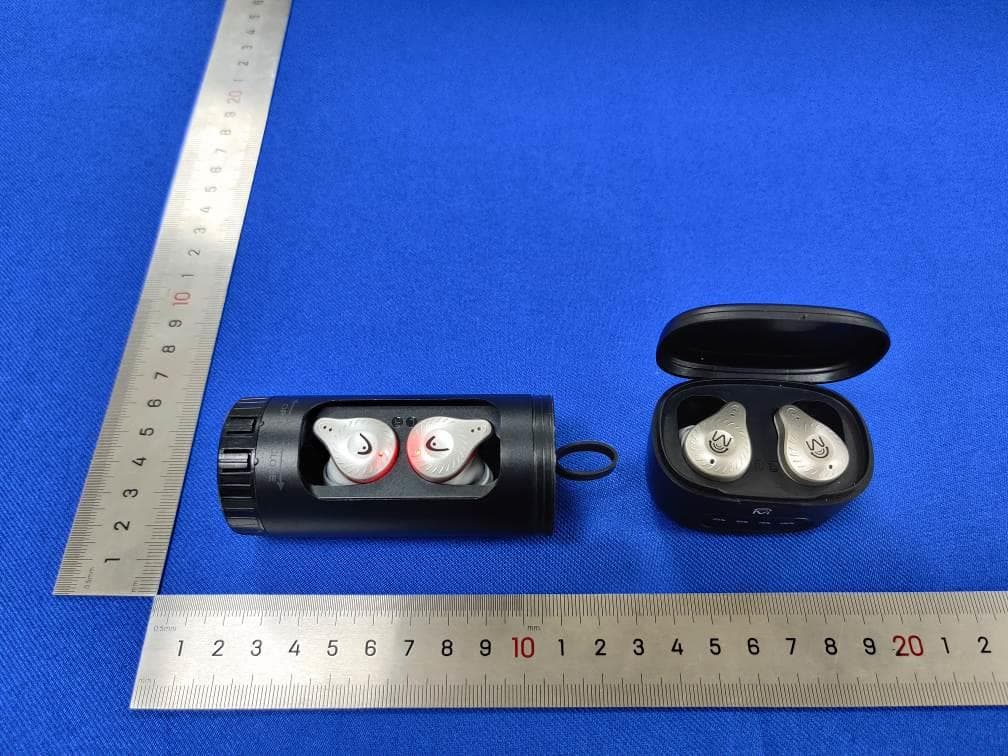
Click to zoom
Application Details
- Equipment Class
- DSS - Part 15 Spread Spectrum Transmitter
- Date of Grant
- May 22, 2023
- Application Purpose
- Original Equipment
- Date of Application
- May 22, 2023
- Equipment Note
- TWS EARBUDS
- Frequency Range
- 2402.00000000 - 2480.00000000
- Company
- CJ Global Inc.
- Country
- United States
Documents & Files
Document Text
Text extracted from the exhibit documents filed with the FCC. Open a document above to read the original.
Users Manual
CLOSED:50x120cm WITH CHARGING CASE ITEM:HWE-30 25353 TWSEARBUDSwithChargingCase USERMANUAL QUICKCONNECTIONGUIDE CAUTION Toavoidpossiblehearingdamage,donot listentomusicathighvolumelevelsforlong periodoftime.Alwayskeepthevolumewithin reasonablelimits. GENERALSAFETYINFORMATION •Keeptheproductandallitspartsoutof reachofsmallchildren. •Thisproductisnotintendedforuseby persons(includingchildren)withreduced physical,sensoryormentalcapabilities,or lackofexperienceandknowledge,unless theyhavebeengivensupervisionor instructionconcerningtheuseofthe appliancebyapersonresponsiblefortheir safety. SPECIFICATIONS Bluetooth5.0 Ultra-lowChargingCase:9hoursof additionalplayback/talkpowerconsumption Earphonechargetime:1hourconnection Distance:10m—15m Chargingcasechargetime:1hour Playbacktime:3hours Earphonebatterycapacity:25mAh Talktime:3hours Chargingcasebatterycapacity:300mAh Standbytime:300hours BLUETOOTHFUNCTIONALITY 1.POWERON:Takeoutthechargingcaseor Pressandholdthetouchbuttonfor5 secondswhenturnedoff. 2.POWEROFF:Putitinthechargingcase,or Pressandholdthetouchbuttonfor5 secondswhenthepoweronis“ON". 3.Bluetoothpairing(pairingwithmobile phone):Takeoutthechargingcaseforthe leftandrightearphones,theearphoneswill automaticallyturnon,connectleftand right,andconnectbacktothelast connectedBluetoothdevice,and automaticallyenterthestateofpairingwith themobilephonewithoutreturning.Long pressthetouchbuttonforabout5seconds tomanuallyenterthepairingstatewhen turnedoff. 4.Connectwithyourmobilephone:The headsetentersthepairingstate,themobile phonesearchesfortheBluetoothpairing name"HEADTWSEarbuds",andclicks Connect 5.Play/Pause:Whilemusicisplaying,click thetouchkeytopauseandclickplayagain. 6.Nextsong/volumedecrease&Previous song/volumeplus:Playmusicstatus, double-clickLforthenextsong/longpress 2secondsvolumedown.Playmusicstatus, double-clickRfortheprevioussong/long press2secondsvolumeplus. 7.Lastnumberredial:Tripletapleftand rightearstocallbacklastnumber. 8.Lowpower:Alowbatterypromptvoice every2minutes 9.Hangupthecall:Clickthetouchkey duringthecall. 10.Rejectincomingcall:Pressandholdfor2 secondstoautomaticallyrejectincomingcall. 11.Hangupthecurrentcallandanswerthe secondcall:whenthereisanothercall, clickthetouchbuttontoendthecurrent callandanswerthesecondcall. 12.Rejectthesecondcall:whenthereis anothercallorthephoneisonhold,press andholdthetouchbuttonfor1.5Storeject thesecondcall. 13.Answerthesecondcallandholdthe currentcall:whenthereisanothercall, double-clicktoholdthecurrentcalland answerthesecondcall 14.Switchbetweentwophonesduringa three-waycall:Whenathree-waycallisin progress,double-clickthetouchkeyto switchbetweenthetwocalls. 15.VoiceAssistant:Fourblowstotheleft andrightearswakeupthevoiceassistant. CHARGINGCASE Therearetwofunctionsofthecharging case:chargingandstoringtheearphones. 1.Charging:Whentheearphonesbatteries arelow,placethemintothechargingcase tobegincharging.Theredlightonthemain buttonofeachearphonewillbesolidred. Whentheearphonesarefullycharged,the redlightsontheearphoneswillshutoff. 2.Storage:Whentheearphonesarenotin use,placetheminsidethechargingcase. Theywillautomaticallydisconnectfrom yourdeviceandbegintocharge.When takingthemoutofthecase,theywill automaticallyreconnecttoyourdevice. FCCSTATEMENT Thisdevicecomplieswithpart15oftheFCC Rules.Operationissubjecttothefollowingtwo conditions:(1)Thisdevicemaynotcauseharmful interference,and(2)thisdevicemustacceptany interferencereceived,includinginterference thatmaycauseundesiredoperation. Note:Thisequipmenthasbeentestedandfound tocomplywiththelimitsforaClassBdigital device,pursuanttopart15oftheFCCRules. Theselimitsaredesignedtoprovidereasonable protectionagainstharmfulinterferenceina residentialinstallation.Thisequipment generates,usesandcanradiateradiofrequency energyand,ifnotinstalledandusedin accordancewiththeinstructions,maycause harmfulinterferencetoradiocommunications. However,thereisnoguaranteethatinterference willnotoccurinaparticularinstallation.Ifthis equipmentdoescauseharmfulinterferenceto radioortelevisionreception,whichcanbe determinedbyturningtheequipmentoffandon, theuserisencouragedtotrytocorrectthe interferencebyoneormoreofthefollowing measures: —Reorientorrelocatethereceivingantenna. —Increasetheseparationbetweentheequipment andreceiver. —Connecttheequipmentintoanoutletona circuitdifferentfromthattowhichthereceiveris connected. —Consultthedealeroranexperiencedradio/TV technicianforhelp. Note:Anychangesormodificationsnotexpressly approvedbythepartyresponsiblefor compliance.suchmodificationscouldvoidthe user'sauthoritytooperatetheequipment. Thedevicehasbeenevaluatedtomeetgeneral RFexposurerequirement. Thedevicecanbeusedinportableexposurecondition withoutrestriction. HEADisaregisteredtrademarkof HEADTechnologyGmbHand HEADSportGmbHandisusedunder licensebyCJGLOBALInc. TheBluetooth®wordmarkandlogosare registeredtrademarksownedbytheBluetooth SIG,Inc.andanyuseofsuchmarksbyCJGlobal isunderlicense.Othertrademarksandtrade namesarethoseoftheirrespectiveowners. CJGlobalInc. Allrightsreserved.2010MapleAveFairLawnNJ 07410. ICSTATEMENT ThisdevicecomplieswithIndustryCanada’s license-exemptRSSs.Operationissubjecttothe followingtwoconditions: 1)Thisdevicemaynotcauseinterference;and 2)Thisdevicemustacceptanyinterference, includinginterferencethatmaycauseundesired operationofthedevice. Thedevicehasbeenevaluatedtomeetgeneral RFexposurerequirement.Thedevicecanbe usedinportableexposureconditionwithout restriction. •Takeouttheleftandrightearphonesfrom thechargingcompartment,theearphones willautomaticallyturnonafteracouple seconds. •Themainearphone(B)willenterthepairing mode(flashingredandbluelight). •Bothearbudswillsyncwitheachother automatically. •EnterBluetoothmodeonyourmobile device,searchfor"HEADTWSEarbuds", andselect.Therewillbeapromptstating, "Connected".Thismeansbothearphones areconnectedandsynceduptoyour mobiledevice. SAFETYINSTRUCTIONS Pleasereadtheseinstructionscarefully beforeoperatingthisdevice. POWERSOURCE •Onlyusethepowersupplythatcamewith theproduc…
Text truncated - open the document above for the full version.
External Photos
EUT EXTERNAL PHOTO
ID Label/Location Info
________________________________________________________________________________ _________ LABEL AND LOCATION Label Remark: Due to the small size of the product, the sample label is silkscreened on the charging case. Label Remark: Due to the small size of the product, the sample label is silkscreened on the charging case. Label Location TWS EARBUDS Model No.: HWE-30 Input: 5V500mA FCC ID: 2AND8-TWS2304 IC: 23749-TWS2304 TWS EARBUDS Model No.: 25353 Input: 5V500mA FCC ID: 2AND8-TWS2304 IC: 23749-TWS2304 Label Location
Internal Photos
EUT INTERNAL PHOTO Antenna Antenna
RF Exposure Info
FCC ID: 2AND8-TWS2304 RF Exposure Evaluation According to KDB 447498 D01 General RF Exposure Guidance v06 and part 2.1093, Unless specifically required by the published RF exposure KDB procedures, standalone 1-g head or body and 10-g extremity SAR evaluation for general population exposure conditions, by measurement or numerical simulation, is not required when the corresponding SAR Test Exclusion Threshold condition(s), listed below, is (are) satisfied. For 100 MHz to 6 GHz and test separation distances ≤ 50 mm, the 1-g and 10-g SAR test exclusion thresholds are determined by the following: [(max. power of channel, including tune-up tolerance, mW) / (min. test separation distance, mm)] · [√f (GHz) ] ≤ 3.0 for 1-g SAR, and ≤ 7.5 for 10-g extremity SAR, where f (GHz) is the RF channel transmit frequency in GHz Power and distance are rounded to the nearest mW and mm before calculation The result is rounded to one decimal place for comparison Here, For BT Mode Max Power( dBm) Turn-up Power Tolerance (dB) Output power (Turn-up Procedure) (mW) Frequency (MHz) Min. distance(mm) Calc. thresholds limit GFSK 2.85 3±1 2.512 2441 5 0.785 3.0 π/4-DQPSK 3.0 3±1 2.512 2441 5 0.785 3.0 8-DPSK 3.11 3±1 2.512 2480 5 0.791 3.0 So a SAR test is not required
Test Report
咏成國際科技有限公司 RAINInternationalTechnologyCo.,Ltd13530576606 2.4GHz3216ChipAntenna:3216F245M02 第 1 页共 10 页 3216Chipantenna ForBluetooth/WLANApplicationsd P/N:RANT3216F245G2 Dimension(mm) L3.23±0.20 W1.66±0.20 T1.23±0.20 咏成國際科技有限公司 RAINInternationalTechnologyCo.,Ltd13530576606 2.4GHz3216ChipAntenna:3216F245M02 第 2 页共 10 页 PartNumberInformation RANT 3216F245G2 ABCDEF A ProductSeriesAntenna BDimensionLxW3.2X1.6mm(+-0.2mm) CMaterialHighKmaterial D WorkingFrequency2.4~2.5GHz E FeedingmodeMonopole&SingleFeeding F AntennatypeType=02 1.ElectricalSpecification Specification PartNumberRANT3216F245M02 CentralFrequency2450MHz Bandwidth100(Min.)MHz ReturnLoss-6.5(Max)dB PeakGain2.71dBi Impedance50Ohm OperatingTemperature -40~+85°C MaximumPower4W ResistancetoSolderingHeats 10(@260 °C ) sec. PolarizationLinear AzimuthBeamwidthOmni-directional TerminationCu/Sn(Leadless) Remark:Bandwidth&PeakGainwasmeasuredunderevaluationboardofnextpage 咏成國際科技有限公司 RAINInternationalTechnologyCo.,Ltd13530576606 2.4GHz3216ChipAntenna:3216F245M02 第 3 页共 10 页 2.RecommendedPCBPattern EvaluationBoardDimension Unit:mm SuggestedMatchingCircuit 咏成國際科技有限公司 RAINInternationalTechnologyCo.,Ltd13530576606 2.4GHz3216ChipAntenna:3216F245M02 第 4 页共 10 页 LayoutDimensionsinClearancearea ( Size=5.2*5.0mm ) 50ohmtransmissionLine MatchingCircuit FootPrint(Unit:mm) 咏成國際科技有限公司 RAINInternationalTechnologyCo.,Ltd13530576606 2.4GHz3216ChipAntenna:3216F245M02 第 5 页共 10 页 3.MeasurementResults ReturnLoss 咏成國際科技有限公司 RAINInternationalTechnologyCo.,Ltd13530576606 2.4GHz3216ChipAntenna:3216F245M02 第 6 页共 10 页 RadiationPattern Y X Z EfficiencyPeakGainDirectivity 2400MHz55.21%1.45dBi5.32dBi 2450MHz66.45%2.71dBi5.21dBi 2500MHz57.53%1.98dBi5.29dBi ChamberCoordinateSystem 咏成國際科技有限公司 RAINInternationalTechnologyCo.,Ltd13530576606 2.4GHz3216ChipAntenna:3216F245M02 第 7 页共 10 页 4.ReliabilityandTestCondictions ITEMREQUIREMENTSTESTCONDITION Solderability1.Wettingshallexceed90%coverage 2.Novisiblemechanicaldamage TEMP(°C) 230°C 4±1sec. 150 °C 60sec Pre-heatingtemperature:150°C/60sec. Soldertemperature:230±5°C Duration:4±1sec. Solder:Sn-Ag3.0-Cu0.5 Fluxforleadfree:rosin Solderheat Resistance 1.Novisiblemechanicaldamage 2.CentralFreq.change:within±6% TEMP(°C) 260°C 10±0.5sec. 150°C 60sec Pre-heatingtemperature:150°C/60sec. Soldertemperature:260±5°C Duration:10±0.5sec. Solder:Sn-Ag3.0-Cu0.5 Fluxforleadfree:rosin Component Adhesion (Pushtest) 1.Novisiblemechanicaldamage Thedeviceshouldbereflow soldered(230±5°Cfor10sec.)toatinned coppersubstrateAdynometerforce gaugeshouldbeappliedthesideofthe component.Thedevicemustwith-ST-F 0.5Kgwithoutfailureofthetermination attachedtocomponent. Component Adhesion (Pulltest) 1.Novisiblemechanicaldamage Insert10cmwireintotheremainingopen eyebend,theendsofevenwirelengths upwardandwindtogether. Terminalshallnotberemarkably damaged. 咏成國際科技有限公司 RAINInternationalTechnologyCo.,Ltd13530576606 2.4GHz3216ChipAntenna:3216F245M02 第 8 页共 10 页 Thermalshock 1.Novisiblemechanicaldamage 2.CentralFreq.change:within±6% Phase Temperature( °C ) Time(min) 1 +85±5°C 30±3 2 RoomWithin Temperature3sec 3 -40±2 °C 30±3 4 RoomWithin Temperature3sec +85 °C =>30±3min -40 °C =>30±3min Testcycle:10cycles Thechipshallbestabilizedatnormal conditionfor2~3hoursbefore measuring. Resistanceto High Temperature 1.Novisiblemechanicaldamage 2.CentralFreq.change:within±6% 3.Nodisconnectionorshortcircuit. Temperature:85±5 °C Duration:1000±12hrs Thechipshallbestabilizedatnormal conditionfor2~3hoursbefore measuring. Resistanceto Low Temperature 1.Novisiblemechanicaldamage 2.CentralFreq.change:within±6% 3.Nodisconnectionorshortcircuit. Temperature:-40±5 °C Duration:1000±12hrs Thechipshallbestabilizedatnormal conditionfor2~3hoursbefore measuring. Humidity 1.Novisiblemechanicaldamage 2.CentralFreq.change:within±6% 3.Nodisconnectionorshortcircuit. Temperature:40±2°C Humidity:90%to95%RH Duration:1000±12hrs Thechipshallbestabilizedatnormal conditionfor2~3hoursbefore measuring. 5.SolderingandMounting Mildlyactivatedrosinfluxesarepreferred.Theminimumamountofsoldercan leadtodamagefromthestressescausedbythedifferenceincoefficientsof expansionbetweensolder,chipandsubstrate.Theterminationsaresuitable forallwaveandre-flowsolderingsystems.Ifhandsolderingcannotbe avoided,thepreferredtechniqueistheutilizationofhotairsolderingtools. ReflowSoldering PRE-HEATING 250~260 230 180 150 SOLDERING 10smax. NATURAL COOLING IronSoldering PRE-HEATINGSOLDERINGNATURAL COOLING 60~120s30~60s TIME(sec.) TIME(sec.) Recommendedtemperatureprofilesforre-flowsolderinginFigure1. Productsattachmentwithasolderingironisdiscouragedduetotheinherent processcontrollimitations.Intheeventthatasolderingironmustbe employedthefollowingprecautionsarerecommended. within3s 350 150 Over60s Gradualcooling 300 T E M P E R A T U R E ( ° C ) T E M P E R A T U R E ( ° C ) 咏成國際科技有限公司 RAINInternationalTechnologyCo.,Ltd13530576606 2.4GHz3216ChipAntenna:3216F245M02 第 9 页共 10 页 1.593.511.80 ‧Preheatcircuitandproductsto150°C ‧Nevercontacttheceramicwiththeirontip ‧Usea20wattsolderingironwithtipdiameterof1.0mm ‧280°Ctiptemperature(max) ‧1.0mmtipdiameter(max) ‧Limitsolderingtimeto3sec. 6.PackagingInformation TapeSpecification: ReelSpecification:(7’’,Φ180mm) 咏成國際科技有限公司 RAINInternationalTechnologyCo.,Ltd13530576606 2.4GHz3216ChipAntenna:3216F245M02 第 10 页共 10 页 TapeWidth(mm)A(mm)B(mm)C(mm)D(mm)Chip/Reel(pcs) 89.0±0.560±213.5±0.5178±25000 7.StorageandTransportationInformation StorageConditions Tomaintainthesolderabilityofterminalelectrodes: 1.Temperatureandhumidityconditions:-10~40°Cand30~70%RH. 2.Recommendedproductsshouldbeusedwithin6monthsfromthetimeof delivery. 3.Thepackagingmaterialshouldbekeptwherenochlorineorsulfurexists intheair. TransportationConditions 1.Productsshouldbehandledwithcaretoavoiddamageorcontamination fromperspirationandskinoils. 2.Theuseoftweezersorvacuumpickupisstronglyrecommendedfor individualcomponents. 3.Bulkhandlingshouldensurethatabrasionandmechanicalshockare minimized.
Test Report
Project No.: ZKT-230421L2878E Page 1 of 72 FCC TEST REPORT FCC ID: 2AND8-TWS2304 Report Number. ................................ : ZKT-230421L2878E Date of Test ..................................................: April. 18, 2023 to May. 05, 2023 Date of issue ..................................... : May. 09, 2023 Total number of pages ....................... 78 Test Result ...................................... : PASS Testing Laboratory. ........................ : Shenzhen ZKT Technology Co., Ltd. Address ........................................... : 1/F, No. 101, Building B, No. 6, Tangwei Community Industrial Avenue, Fuhai Street, Bao'an District, Shenzhen, China Applicant's name ......................... : CJ Global Inc. Address ........................................... : 20-21 Wagaraw Road Bldg 30 Fair Lawn, New Jersey, United States 07410 Manufacturer's name ................... : CJ Global Inc. Address ........................................... : 20-21 Wagaraw Road Bldg 30 Fair Lawn, New Jersey, United States 07410 Test specification: Standard ........................................... : FCC CFR Title 47 Part 15 Subpart C Section 15.247 ANSI C63.10:2013 Test procedure ................................. : / Non-standard test method .............. : N/A Test Report Form No. .................... : TRF-EL-112_V0 Test Report Form(s) Originator .... : ZKT Testing Master TRF ................................... : Dated: 2021-04-22 This device described above has been tested by ZKT, and the test results show that the equipment under test (EUT) is in compliance with the FCC requirements. And it is applicable only to the tested sample identified in the report. This report shall not be reproduced except in full, without the written approval of ZKT, this document may be altered or revised by ZKT, personal only, and shall be noted in the revision of the document. Product name ................................. : TWS EARBUDS Trademark ....................................... : N/A Model/Type reference ....................... : HWE-30, 25353 Ratings .............................................. : DC 3.7V by Battery and charged by charging case. Project No.: ZKT-230421L2878E Page 2 of 72 Testing procedure and testing location: Testing Laboratory ..................................... : Shenzhen ZKT Technology Co., Ltd. Address ...................................................... : 1/F, No. 101, Building B, No. 6, Tangwei Community Industrial Avenue, Fuhai Street, Bao'an District, Shenzhen, China Alen He Tested by (name + signature) .................... : Kevin Huang Reviewer (name + signature) ..................... : Lake Xie Approved (name + signature) .................... : Project No.: ZKT-230421L2878E Page 3 of 72 Table of Contents Page 1. VERSION ............................................................... 5 2. TEST SUMMARY ........................................................ 6 2.1 TEST FACILITY ......................................................... 7 2.2 MEASUREMENT UNCERTAINTY ......................................... 7 3. GENERAL INFORMATION ................................................ 8 3.1 GENERAL DESCRIPTION OF EUT ........................................ 8 3.2 Test Setup Configuration .................................................. 9 3.3 Support Equipment ....................................................... 9 3.4 Test Mode ............................................................. 10 3.5 EQUIPMENTS LIST FOR ALL TEST ITEMS ................................ 11 4. EMC EMISSION TEST ................................................... 12 4.1 Conducted emissions .................................................... 12 4.1.1 POWER LINE CONDUCTED EMISSION Limits ........................... 12 4.1.2 TEST PROCEDURE ................................................... 12 4.1.3 DEVIATION FROM TEST STANDARD ................................... 12 4.1.4 TEST SETUP ......................................................... 12 4.1.5 EUT OPERATING CONDITIONS ........................................ 13 4.1.6 Test Result ........................................................... 13 4.2 Radiated emissions ..................................................... 14 4.2.1 Radiated Emission Limits ............................................... 14 4.2.2 TEST PROCEDURE ................................................... 14 4.2.3 DEVIATION FROM TEST STANDARD ................................... 15 4.2.4 TEST SETUP ......................................................... 15 4.2.5 EUT OPERATING CONDITIONS ........................................ 16 4.2.6 TEST RESULTS ...................................................... 17 5. RADIATED BAND EMISSION MEASUREMENT ............................ 26 5.1 Test Requirement: ...................................................... 26 5.2 TEST PROCEDURE .................................................... 26 5.3 DEVIATION FROM TEST STANDARD .................................... 27 5.4 TEST SETUP .......................................................... 27 5.5 EUT OPERATING CONDITIONS ......................................... 27 5.6 TEST RESULT ......................................................... 28 6. CONDUCTED BAND EDGE AND SPURIOUS EMISSION .................... 30 6.1 Limit ................................................................... 30 6.2 Test Setup ............................................................. 30 6.3 Test procedure ......................................................... 30 6.4 DEVIATION FROM STANDARD .......................................... 30 6.5 Test Result ............................................................. 31 7. 20DB&99% BANDWIDTH ................................................ 42 7.1 Test Setup ............................................................. 42 7.2 Limit ................................................................... 42 7.3 Test procedure ....................................................…
Text truncated - open the document above for the full version.
Test Setup Photos
EUT Test Setup photo
Contact Information
Applicant
Coby Chen(Manager)
Test Firm
Shenzhen ZKT Technology Co., Ltd.Lake Xie
[email protected]0086-13620010775
Technical Specifications
| # | Rule Parts | Frequency Range | Power Output |
|---|---|---|---|
| 1 | 15C | 2.40 GHz - 2.48 GHz | 2.00 mW |
Other Applications from CJ Global Inc.
2AND8-71485-BO
Jul 31, 2026Bobcat Neckband Headphones
Equipment Class
DSS - Part 15 Spread Spectrum Transmitter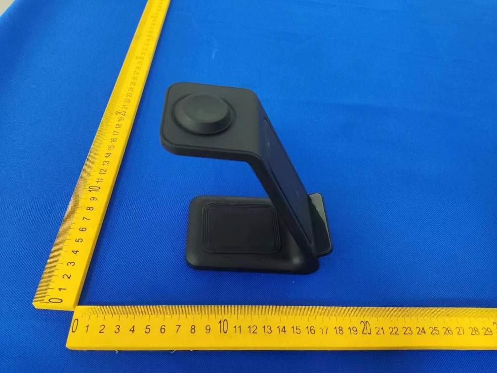
2AND8-CHG3N1
Aug 07, 20233-In-1 Fast Wireless Charging Station
Equipment Class
DCD - Part 15 Low Power Transmitter Below 1705 kHz2AND8-CH2207
Jul 25, 20224-in-1 Fast Wireless Charging Station With Lamp
Equipment Class
DCD - Part 15 Low Power Transmitter Below 1705 kHz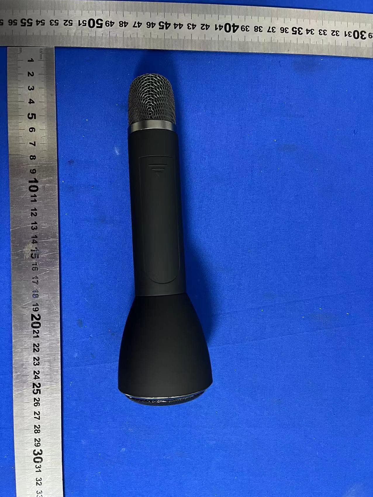
2AND8-BT2205
Jul 19, 2022Karaoke Wireless Microphone
Equipment Class
DSS - Part 15 Spread Spectrum Transmitter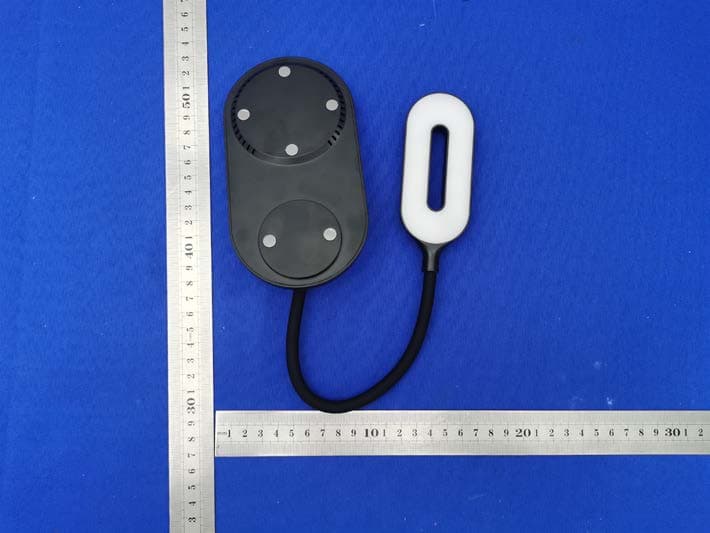
2AND8-24724
Aug 09, 2021Flex Neck Lamp Wireless Charger
Equipment Class
DCD - Part 15 Low Power Transmitter Below 1705 kHz