2ANDL-ZS4S-IPEXZigbee Module
Hangzhou Tuya Information Technology Co.,Ltd
Click to zoom
Application Details
- Equipment Class
- DTS - Digital Transmission System
- Date of Grant
- Aug 25, 2021
- Application Purpose
- Original Equipment
- Date of Application
- Aug 24, 2021
- Equipment Note
- Zigbee Module
- Frequency Range
- 2405.00000000 - 2480.00000000
- Country
- China
Documents & Files
Document Text
Text extracted from the exhibit documents filed with the FCC. Open a document above to read the original.
Users Manual
ZS4S-IPEX Module Datasheet Version: 20210818 Online Version Contents Contents 1 Product overview2 1.1 Features. . . . . . . . . . . . . . . . . . . . . . . . . . . . . . . . .2 1.2 Applications. . . . . . . . . . . . . . . . . . . . . . . . . . . . . . .2 1.3 Change history. . . . . . . . . . . . . . . . . . . . . . . . . . . . . .3 2 Module interfaces4 2.1 Dimensions and footprint. . . . . . . . . . . . . . . . . . . . . . . .4 2.2 Pin definition. . . . . . . . . . . . . . . . . . . . . . . . . . . . . . .5 3 Electrical parameters9 3.1 Absolute electrical parameters. . . . . . . . . . . . . . . . . . . . .9 3.2 Working conditions. . . . . . . . . . . . . . . . . . . . . . . . . . .9 3.3 Zigbee TX power consumption. . . . . . . . . . . . . . . . . . . . .10 3.4 Zigbee RX power consumption. . . . . . . . . . . . . . . . . . . . .10 3.5 Power consumption in working mode. . . . . . . . . . . . . . . . . .11 3.6 RF features. . . . . . . . . . . . . . . . . . . . . . . . . . . . . . . .11 3.7 Basic RF features. . . . . . . . . . . . . . . . . . . . . . . . . . . .11 3.8 Zigbee output performance. . . . . . . . . . . . . . . . . . . . . . .11 3.9 Zigbee RX sensitivity. . . . . . . . . . . . . . . . . . . . . . . . . .12 4 Antenna information13 4.1 Antenna type. . . . . . . . . . . . . . . . . . . . . . . . . . . . . .13 4.2 Antenna interference reduction. . . . . . . . . . . . . . . . . . . . .13 5 Packaging information and production instructions14 5.1 Mechanical dimensions. . . . . . . . . . . . . . . . . . . . . . . . .14 5.2 Side view. . . . . . . . . . . . . . . . . . . . . . . . . . . . . . . .16 5.3 Production instructions. . . . . . . . . . . . . . . . . . . . . . . . .17 5.4 Recommended oven temperature curve. . . . . . . . . . . . . . . . .18 5.5 Storage conditions. . . . . . . . . . . . . . . . . . . . . . . . . . . .20 6 MOQ and packaging information21 7 Appendix: Statement22 I Contents ZS4S-IPEX is a Zigbee module that Tuya has developed. It consists of a highly integrated RF processing chip (EFR32MG13P732F512GM48), a few peripherals, a 802.15.4 PHY/MAC Zigbee network protocol stack, and rich library functions. 1 / 24 1 Product overview 1 Product overview ZS4S-IPEX is embedded with a low-power 32-bit ARM Cortex-M4 core, 512-KB flash program memory, 64-KB RAM, and rich peripherals. It integrates all function li- braries of the Zigbee MAC and TCP/IP. You can develop embedded Zigbee products as required. 1.1 Features •Embedded with a low-power 32-bit CPU having a Cortex-M4 processor, DSP instructions, and uping-point units, which can also function as an application processor •Clock rate: 40 MHz •Wide operating voltage: 2.4 to 3.8 V •Peripherals: 9 GPIOs and 1 UART •Zigbee connectivity –Support 802.15.4 MAC/PHY –Channels 11 [email protected] 2.483 GHz Air interface rate: 250 Kbps –Built-in DC-DC circuit, which improves the power efficiency to the greatest extent –Up to +18dBm output power and dynamic output power > 35 dB –60 uA/MHz power consumption during running, 3.5uA sleep current –The terminal device connects to the network actively. –The Ipex connector can be used with an external antenna with a gain of 3.3dBi. –Operating temperature: -20°C to 85°C –Support hardware encryption and AES 128/256 1.2 Applications •Intelligent building •Smart household and home appliances •Smart socket and light •Industrial wireless control •Baby monitor 2 / 24 1 Product overview •Network camera •Intelligent bus 1.3 Change history Update dateUpdated content Version after update June 4th, 2021This is the first release. V1.0.0 3 / 24 2 Module interfaces 2 Module interfaces 2.1 Dimensions and footprint The ZS4S-IPEX dimensions are 20.9±0.35 mm (W)×28.0±0.35 mm (L) ×3.5±0.15 mm (H), which are shown below: 4 / 24 2 Module interfaces 2.2 Pin definition Pin numberSymbolTypeFunction 1nRSTIReset pin The chip is reset at low level. The module has its own power-on reset pin, so users may not use this pin according to the actual situation. 5 / 24 2 Module interfaces Pin numberSymbolTypeFunction 2PB11I/OPort for debugging the PTI (Packet trace interface), which corresponds to Pin 31 3SWDIOI/OCommunication interface for JLINK burning, which can be configured as a GPIO in the application, and corresponds to PF1 (Pin 2) 4SWCLKI/OClock signal of JLINK burning, which can be configured as GPIO in the application, and corresponds to PF0 (Pin 1) 5F_RXI/OReceiving port of production, which corresponds to PF2 (Pin 3) 6 PF4 I/O Used as GPIO and correspond to PF4 (Pin 5) 7F_TXI/OTransmitting port of production, which corresponds to PF5 (Pin 6) 6 / 24 2 Module interfaces Pin numberSymbolTypeFunction 83.3VPPower supply pin of the module (The typical power supply voltage is 3.3V) 9GNDPPower supply reference ground 10PA3I/OReserved full-interface UART RTS signal, which can also be used as GPIO in the application and corresponds to Pin 28 11PB13I/OPTI debugging port, FRC_DFRAME. Target packet trace interface Frame signal. Correspond to Pin 33. 12PB12I/OPTI debugging port, FRC_DOUT, PTI data signal, corresponding to Pin 32 13PA2I/OReserved PWM output, which can also be used as GPIO, and corresponds to Pin 27) 7 / 24 2 Module interfaces Pin numberSymbolTypeFunction 14PA4I/OReserved full-interface UART CTS signal, which corresponds to Pin 29 15RXI/OUART0_RXD, receiving interface, which is connected to UART_TX of the external host computer and corresponds to PA 1 (Pin 26) 16TXI/OUART0_TXD, transmitting interface, which is connected to UART_RX of the external host computer and corresponds to PA 0 (Pin 25) Note: •P indicates a power supply pin and I/O indicates an input/output pin. •nRST is only a reset pin of the module and cannot be used for clearing Zigbee networking information. 8 / 24 3 Electrical parameters 3 Electrical parameters 3.1 Absolute electrical parameters ParameterDescription Minimum value Maximum valueUnit TsStorage temperature -50150°C VCCPower supply voltage -0.33.8V ESD voltage (human body model) TAMB-25°C-2.5KV ESD volt…
Text truncated - open the document above for the full version.
Cover Letter(s)
Company: Hangzhou Tuya Information Technology Co.,Ltd Address: Room701,Building3,More Center,No.87 GuDun Road, Hangzhou,Zhejiang, China Tel: 86-571-86581786 Fax: 86-571-86581786 Date (01/03/2020) TUV SUD BABT UNLIMITED TCB Octagon House, Segensworth North, Fareham, Hampshire, PO15 5RL, United Kingdom Dear Sir or Madam, We, (Hangzhou Tuya Information Technology Co.,Ltd;Room701,Building3,More Cent er,No.87 GuDun Road, Hangzhou, Zhejiang, China), hereby authorize Jiaxi XUfrom TÜV SÜD Certification and Testing (China) Co., Ltd. Shanghai Branch3-13, No.151 Heng Tong Road Shanghai 201108P.R. Chinato act as our agent in all matters relating to applications for equipment authorization, including the signing of all documents relating to these matters. This authorization expires on(Dec. 31, 2021). Sincerely, Company Officer:Shou XiaoDong Telephone Number:86-571-86581786 Email: [email protected]
Cover Letter(s)
Company: Hangzhou Tuya Information Technology Co.,Ltd Address: Room701,Building3,More Center,No.87 GuDun Road, Hangzhou,Zhejiang, China Tel: 86-571-86581786 Fax: 86-571-86581786 Date (08/11/2021) TUV SUD BABT UNLIMITED TCB Octagon House, Segensworth North, Fareham, Hampshire, PO15 5RL, United Kingdom Confidentiality Request FCC ID:2ANDL-ZS4S-IPEX Pursuant to Sections 0.457(d)(1)(ii) and 0.459 of the Commission’s Rules,(Hangzhou Tuya Information Technology Co.,Ltd) hereby requests permanent confidential treatment of information accompanying this application as outlined below: Schematics Block Diagrams PCB Layout Theory of Operation The above materials contain trade secrets and proprietary information not customarily released to the public. The public disclosure of these matters might be harmful to the Applicant and provide unjustified benefits to its competitors. The Applicant understands that pursuant to Rule 0.457(d)(1)(ii), disclosure of this Application and all accompanying materials will not be made before the date of the Grant for this Application. Yours sincerely, Company Officer: Telephone Number:86-571-86581786 Email: [email protected]
Cover Letter(s)
Company: Hangzhou Tuya Information Technology Co.,Ltd Address: Room701,Building3,More Center,No.87 GuDun Road, Hangzhou,Zhejiang, China Tel: 86-571-86581786 Fax: 86-571-86581786 Date (08/11/2021) Federal Communications Commission Equipment Authorization Branch 7435 Oakland Mills Road Columbia, MD 21046 Modular Approval Request FCC ID:2ANDL-ZS4S-IPEX The following attestation addresses the requirements to support modular approval: Modular approval requirementYes(provide brief statement)No * (a) The radio elements must have the radio frequency circuitry shielded. Physical components and tuning capacitor(s) may be located external to the shield, but must be on the module assembly The module has a metal shied. Refer to the external photo of EUT. (b) The module must have buffered modulation/data inputs to ensure that the device will comply with Part 15 requirements with any type of input signal Data to the modulation circuit is buffered as described in the operational description provided with the application. (c) The module must contain power supply regulation on the module The module contains its own power supply regulation. Please refer to schematic filed with this application. (d) The module must contain a permanently attached antenna, or The module connects to its antenna using an IPEXconnector Company: Hangzhou Tuya Information Technology Co.,Ltd Address: Room701,Building3,More Center,No.87 GuDun Road, Hangzhou,Zhejiang, China Tel: 86-571-86581786 Fax: 86-571-86581786 contain a unique antenna connector, and be marketed and operated only with specific antenna(s), per Sections 15.203, 15.204(b), 15.204(c), 15.212(a), 2.929(b) which is considered a standard connector. Factory will use the permanent, industrial epoxy, “Loctite” or solder to make the connection permanent before shipping. (e) The module must demonstrate compliance in a stand-alone configuration The module was tested stand- alone as shown in test setup photographs filed with this application. (f) The module must be labelled with its permanently affixed FCC ID label, or use an electronic display (See KDB Publication 784748 about labelling requirements) The FCC ID is printed on the label of the module. Refer to the label of EUT. (g) The module must comply with all specific rules applicable to the transmitter. The grantee must provide comprehensive instructions to explain compliance requirements The module comply with all specific rules. Refer to the datasheet. Modular approval requirementYes(provide brief statement)No * (h) The module must comply with RF exposure requirements Please refer exhibition RF Exposure for the compliance of MPE RF exposure rule. * Please provide a detailed explanation if the answer is “No.” Yours sincerely, Name: Title: General Manager
External Photos
External Photos Documentation Manufacturer: Hangzhou Tuya Information Technology Co.,Ltd Page 1 of 1 Product: Zigbee Module FCC ID: ZS4S-IPEX Antenna
ID Label/Location Info
Label & Location Label position Label
Internal Photos
Internal Photos Documentation Manufacturer: Hangzhou Tuya Information Technology Co.,Ltd Page 1 of 1 Product: Zigbee Module FCC ID: ZS4S-IPEX
RF Exposure Info
Report No: 709502102985-00A EMC_SHA_F_R_02.06E TÜV SÜD Certification and Testing (China) Co., Ltd. Shanghai Branch 3-13, No.151, Heng Tong Road, Shanghai, 200070, P.R. China Phone: +86 21 61410123, Fax:+86 21 61408600 Page 1 of 2 Rev. 20.00 MPE Calculation Applicant: Hangzhou Tuya Information Technology Co.,Ltd Address: Room701,Building3,More Center,No.87 GuDun Road,Hangzhou,Zhejiang China Product: Zigbee Module FCC ID: 2ANDL-ZS4S-IPEX Model No.: ZS4S-IPEX Reference RF report # 709502102985-00 According to subpart 15.247(i)and subpart §1.1307(b)(1), systems operating under the provisions of this section shall be operated in a manner that ensures that the public is not exposed to radio frequency energy level in excess of the Commission’s guidelines. Limits for Maximum Permissible Exposure (MPE) (§1.1310, §2.1091) (B) Limits for General Population/Uncontrolled Exposure Frequency Range (MHz) Electric Field Strength (V/m) Magnetic Field Strength (A/m) Power Density (mW/cm 2 ) Averaging Time (minutes) 0.3–1.346141.63*(100)30 1.34–30824/f2.19/f*(180/f²)30 30–30027.50.0730.230 300–1,500//f/150030 1,500–100,000//1.030 f = frequency in MHz; * = Plane-wave equivalent power density; According to §1.1310 and §2.1091 RF exposure is calculated. Calculated Formulary: Predication of MPE limit at a given distance S = PG/4πR² = power density (in appropriate units, e.g. mW/cm 2 ); P = power input to the antenna (in appropriate units, e.g., mW); G = power gain of the antenna in the direction of interest relative to an isotropic radiator, the power gain factor, is normally numeric gain; R = distance to the center of radiation of the antenna (appropriate units, e.g., cm); Report No: 709502102985-00A EMC_SHA_F_R_02.06E TÜV SÜD Certification and Testing (China) Co., Ltd. Shanghai Branch 3-13, No.151, Heng Tong Road, Shanghai, 200070, P.R. China Phone: +86 21 61410123, Fax:+86 21 61408600 Page 2 of 2 Rev. 20.00 Calculated Data: FPC antenna Maximum peak output power at antenna input terminal (dBm):17.81 Maximum peak output power at antenna input terminal (mW):60.39 Prediction distance (cm):20 Antenna Gain, typical (dBi):3.3 Maximum Antenna Gain (numeric):2.138 The worst case is power density at predication frequency at 20 cm (mW/cm 2 ):0.0257 MPE limit for general population exposure at prediction frequency (mW/cm 2 ):1.0 The max power density 0.0257 (mW/ cm 2 ) < 1 (mW/ cm 2 ) Result: Compliant - TÜV SÜD Certification and Testing (China) Co., Ltd. Shanghai Branch Reviewed by: Prepared by:Tested by: _____________________ ___________________________________________ Hui TONGJiaxi XUWenqiang LU EMC Section ManagerEMC Project EngineerEMC Test Engineer Date: 2021-08-11 Date: 2021-08-11 Date: 2021-08-11
Test Report
EMC_SHA_F_R_02.10E TÜV SÜD Certification and Testing (China) Co., Ltd. Shanghai Branch 3-13, No.151, Heng Tong Road, Shanghai, 200070, P.R. China Phone: +86 21 61410123, Fax:+86 21 61408600 Page 1 of 35 Rev. 20.00 FCC - TEST REPORT Report Number:709502102985-00Date of Issue:August 11, 2021 Model:ZS4S-IPEX Product Type:Zigbee Module Applicant: Hangzhou Tuya Information Technology Co.,Ltd Address: Room701,Building3,More Center,No.87 GuDun Road,Hangzhou,Zhejiang China Manufacturer: Hangzhou Tuya Information Technology Co.,Ltd Address:Room701,Building3,More Center,No.87 GuDun Road,Hangzhou,Zhejiang China TestResult:nPositiveoNegative Total pages including Appendices:35 TÜV SÜD Certification and Testing (China) Co., Ltd. Shanghai Branch is a subcontractor to TÜV SÜD Product Service GmbH according to the principles outlined in ISO 17025. TÜV SÜD Certification and Testing (China) Co., Ltd. Shanghai Branch reports apply only to the specific samples tested under stated test conditions. Construction of the actual test samples has been documented. It is the manufacturer's responsibility to assure that additional production units of this model are manufactured with identical electrical and mechanical components. The manufacturer/importer is responsible to the Competent Authorities in Europe for any modifications made to the production units which result in non-compliance to the relevant regulations. TÜV SÜD Certification and Testing (China) Co., Ltd. Shanghai Branch shall have no liability for any deductions, inferences or generalizations drawn by the client or others from TÜV SÜD Certification and Testing (China) Co., Ltd. Shanghai Branch issued reports. This report is the confidential property of the client. As a mutual protection to our clients, the public and ourselves, extracts from the test report shall not be reproduced except in full without our written approval. Report Number:709502102985-00 EMC_SHA_F_R_02.10E TÜV SÜD Certification and Testing (China) Co., Ltd. Shanghai Branch 3-13, No.151, Heng Tong Road, Shanghai, 200070, P.R. China Phone: +86 21 61410123, Fax:+86 21 61408600 Page 2 of 35 Rev. 20.00 1 Table of Contents 1 Table of Contents .................................................................................................................. 2 2 Details about the Test Laboratory .......................................................................................... 3 3 Description of the Equipment under Test ............................................................................... 4 4 Summary of Test Standards .................................................................................................. 5 5 Summary of Test Results ...................................................................................................... 6 6 General Remarks .................................................................................................................. 7 7 Test Setups ........................................................................................................................... 8 8 Systems test configuration ................................................................................................... 11 9 Technical Requirement ........................................................................................................ 12 9.1 Conducted Emission ..................................................................................................... 12 9.2 Conducted peak output power ...................................................................................... 15 9.3 6dB bandwidth .............................................................................................................. 17 9.4 Power spectral density .................................................................................................. 19 9.5 Spurious RF conducted emissions ............................................................................... 21 9.6 Band edge .................................................................................................................... 25 9.7 Spurious radiated emissions for transmitter .................................................................. 27 10 Test Equipment List .......................................................................................................... 32 11 System Measurement Uncertainty ................................................................................... 33 12 Photographs of Test Set-ups ............................................................................................ 34 13 Photographs of EUT ........................................................................................................ 35 Report Number:709502102985-00 EMC_SHA_F_R_02.10E TÜV SÜD Certification and Testing (China) Co., Ltd. Shanghai Branch 3-13, No.151, Heng Tong Road, Shanghai, 200070, P.R. China Phone: +86 21 61410123, Fax:+86 21 61408600 Page 3 of 35 Rev. 20.00 2 Details about the Test Laboratory Details about the Test Laboratory Test Site 1 Company name:TÜV SÜD Certification and Testing (China) Co., Ltd. Shanghai Branch No.16 Lane, 1951 Du Hui Road, Shanghai 201108, P.R. China Test Firm FCC Registration Number: 820234 Test Firm IC Registration Number: 25988 Telephone:+86 21 61410123 Fax:+86 21 6140 8600 Report Number:709502102985-00 EMC_SHA_F_R_02.10E TÜV SÜD Certification and Testing (China) Co., Ltd. Shanghai Branch 3-13, No.151, Heng Tong Road, Shanghai, 200070, P.R. China Phone: +86 21 61410123, Fax:+86 21 61408600 Page 4 of 35 Rev. 20.00 3 Description of the Equipment under Test Description of the Equipment Under Test Product:Zigbee Module Model no.:ZS4S-IPEX FCC ID: 2ANDL-ZS4S-IPEX Options and accessories:NA Rating:DC 2.4-3.8V RF Transmission Frequency:2405~2480MHz No. of Operated Channel:16 Modulation:O-QPSK Channel list: Antenna Type:FPC Antenna Antenna Gain:3.3 dBi Description of the EUT:The Equipment Under Test (EUT) is a Zigbee Module. We tested it…
Text truncated - open the document above for the full version.
Contact Information
Applicant
Linyun Li(Manager)
Test Firm
TUV SUD Certification and Testing (China) Co., LtdYi Ba
[email protected]86 21 6140 0132
Technical Specifications
| # | Rule Parts | Frequency Range | Power Output |
|---|---|---|---|
| 1 | 15C | 2.40 GHz - 2.48 GHz | 60.39 mW |
Other Applications from Hangzhou Tuya Information Technology Co.,Ltd
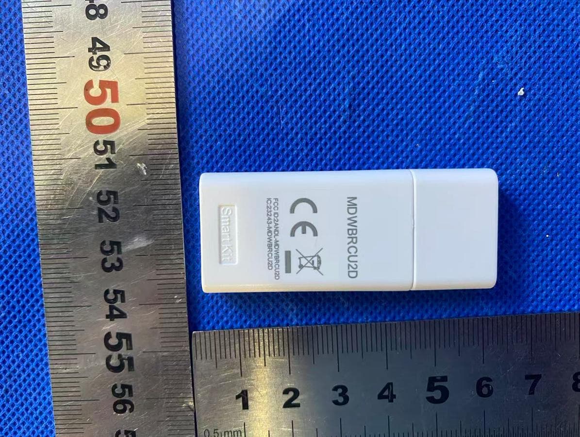
2ANDL-MDWBRCU2D
Aug 14, 2026Smart Kit
Equipment Class
DTS - Digital Transmission System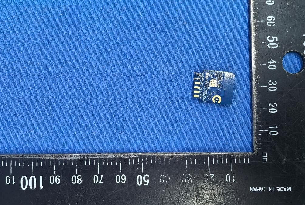
2ANDL-T72S
Jun 25, 2026Wi-Fi and Bluetooth Module
Equipment Class
NII - Unlicensed National Information Infrastructure TX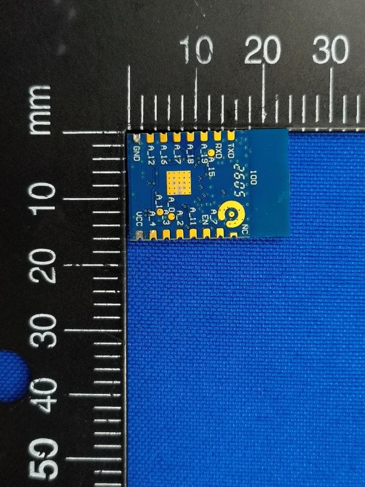
2ANDL-WBR3PRO
May 12, 2026Wi-Fi and Bluetooth Module
Equipment Class
DTS - Digital Transmission System2ANDL-WR113S
Apr 20, 2026Wi-Fi and Bluetooth Module
Equipment Class
NII - Unlicensed National Information Infrastructure TX2ANDL-T7U
Mar 27, 2026Wi-Fi and Bluetooth Module
Equipment Class
NII - Unlicensed National Information Infrastructure TX