2ANPB-RPS100150AAPhoenix 1000 Portable Power Station
RNG International Inc.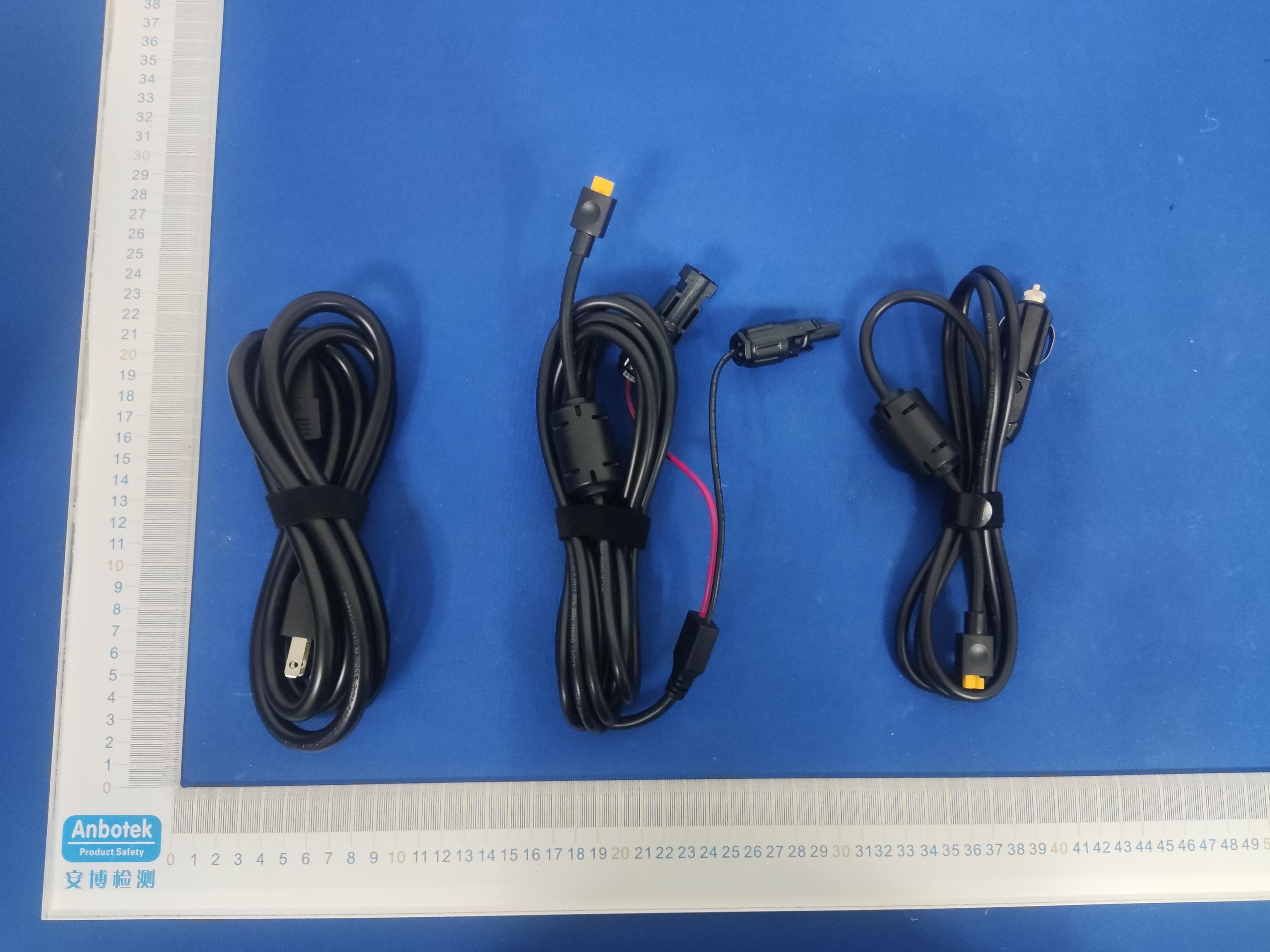
Click to zoom
Application Details
- Equipment Class
- DTS - Digital Transmission System
- Date of Grant
- Aug 17, 2022
- Application Purpose
- Original Equipment
- Date of Application
- Aug 17, 2022
- Equipment Note
- Phoenix 1000 Portable Power Station
- Frequency Range
- 2402.00000000 - 2480.00000000
- Company
- RNG International Inc.
- Country
- United States
Documents & Files
Document Text
Text extracted from the exhibit documents filed with the FCC. Open a document above to read the original.
Users Manual
PHOENIX 1000 Portable Power Station Version A0 - 01 - APPLICABILITY The User Manual applies to the following product: • PHOENIX 1000 Portable Power Station (RPS100150AA-PCS) DISCLAIMER • User Manual because continuous product improvements are going to be made. • Renogy assumes no responsibility or liability for losses or damages, whether direct, indirect, consequential, or incidental, which might arise out of the use of information in the User Manu- al. • Renogy is not responsible or liable for the failures, damages, or injuries resulting from repair • The illustrations in the User Manual are for demonstration purposes only. Details may appear • Renogy reserves the right to change the information in the User Manual without notice. COPYRIGHT PHOENIX 1000 Portable Power Station User Manual © 2022 Renogy. All rights reserved. All information in the User Manual is subject to copyright and other intellectual property rights whole or in part, without the prior written permissions of Renogy and its licensors. TRADEMARKS The following are trademarks or registered trademarks of Renogy in the United States and other countries: RENOGY All other trademarks in the User Manual are the property of their respective owners and their use herein does not imply sponsorship or endorsement of their products or services. The unau- thorized use of any trademark displayed in the User Manual or on the product is strictly prohibit- ed. - 02 - Import ant Safety Instructions Please save these instructions. The User Manual provides important operation and maintenance instructions for PHOENIX 1000 Portable Power Station. Please read the User Manual carefully before operation and save it for future reference. Failure to observe the instructions or precautions in the User Manual can result in electrical shock, serious injury, or death, or can damage PHOENIX, potentially rendering it inoperable. Symbols Used The following symbols are used throughout the User Manual to highlight important information. Indicates a potentially dangerous condition which could result in injury or death. Indicates a critical procedure for safe and proper installation and operation. Indicates an important step or tip for optimal performance. General Safety Information • DO NOT immerse PHOENIX in water or leave it out in the rain. • DO NOT puncture, drop, crush, penetrate, shake, strike, or step on PHOENIX. • DO NOT open, dismantle, repair, tamper with, or modify PHOENIX. • DO NO insert foreign objects into the casing or outlets of PHOENIX. • • • • Please keep PHOENIX away from heating equipment. • DO NOT touch the exposed electrolyte or powder if PHOENIX is damaged. • DO NOT use PHOENIX with life support equipment or other medical equipment. • Please keep PHOENIX out of the reach of young children. • DO NOT dispose of PHOENIX as household waste. Please recycle PHOENIX in accordance with local, state, and federal regulations. • Please inspect PHOENIX before each use. Stop using PHOENIX if any visible damages in- cluding cracks, dents, and deformation or abnormalities including unusual smells and heating are observed. - 03 - • • • • Please ensure that no water sources including downspouts, sprinklers, or faucets are above or near PHOENIX. • Please ensure that snow does not accumulate around PHOENIX. • DO NOT lean on, stack anything on top of, or hang anything from PHOENIX or from cables leading to PHOENIX. • Please ensure that PHOENIX is securely fastened during transportation. - 04 - Table of Contents Product Overview -----------------------------------------------------05 ------------------------------------------------05 Package Content----------------------------------------------------07 LCD Display----------------------------------------------------------08 Operation -----------------------------------------------------------10 ----------------------------------------------------10 DC Home Connection -----------------------------------------------10 Charging ---------------------------------------------------------13 Powering Devices - - - - - - - - - - - - - - - - - - - - - - - - - - - - - - - - - - - - - - - - - - - - - - - - - - - 15 Standby Power Supply (SPS) ------------------------------------------17 Parallel Connection--------------------------------------------------18 Strip Lights Operation ------------------------------------------------20 Timeout Settings----------------------------------------------------20 Maintenance ---------------------------------------------------------22 Cleaning ---------------------------------------------------------22 Storage ---------------------------------------------------------22 Troubleshooting ------------------------------------------------------23 - - - - - - - - - - - - - - - - - - - - - - - - - - - - - - - - - - - - - - - - - - - - - - - - - - - - - - - - 28 - 05 - Product Overview United St ates /Canada/Ja pan Euro pe /South Kore a China United Ki ngdomAust ra lia - 06 - LCD Display CIG Port LED Strip Lights AC Outlets Overload Protector AC Inlet DC Input Port Parallel Outlet - 07 - Package Content PHOENIX 1000 Portable Power S tatio n AC P ower Cable Car C harge Cable User M anualSola r C harge Cable - 08 - LCD Display IconNameDescription Indicates the current battery level. As the PHOE- NIX charges, the ring will light up clockwise with the increasing percentage, and the endmost ring segment will fast flash. Once PHOENIX is fully charged, all the ring segments will light up and re- main solid. As the PHOENIX discharges, the ring will go out counterclockwise. When the battery lev- el drops below 10%, the last ring segment will slow Input Power Indicates the amount of power going int o PHOE- NIX. Output Power Indicates the amount of power going out of PHOE- NIX. Remaining Time Indicates the amount of time before PHOENIX is completely charged or discharged. When PHOE- NIX idles, the remaining time will show 99 hours. AC Outlet Status the AC Outlet(s). - 09 - IconNameDescription CIG Port St…
Text truncated - open the document above for the full version.
Cover Letter(s)
RNGInternationalInc. OfficeofEngineeringTechnology FederalCommunicationsCommission 7435OaklandMillsRoad Columbia,MD21046 USA Date:2022-08-16 Subject;RequestforConfidentiality FCCID:2ANPB-RPS100150AA ToWhomItMayConcern, PursuanttotheprovisionsoftheCommission’srulesTitle47Sections§0.457and§0.459,we arerequestingtheCommissiontowithholdthefollowingattachment(s)asconfidential documentsfrompublicdisclosureindefinitely. Thesedocumentscontaindetailedsystemandequipmentdescriptionsandareconsideredas proprietaryinformationinoperationoftheequipment.Thepublicdisclosureofthesedocuments mightbeharmfultoourcompanyandwouldgivecompetitorsanunfairadvantageinthemarket. SchematicDiagram BlockDiagram OperationalDescription SWSECURITYDESCRIPTION PartsList Tuneup Inadditionaltoabovementioneddocuments,inordertocomplywiththemarketingregulations inTitle47CFR§2.803andtheimportationrulesinTitle47CFR§2.1204,whileensuringthat businesssensitiveinformationremainsconfidentialuntiltheactualmarketingofnewly authorizeddevices,werequestShortTermConfidentialityofthefollowingattachment(s); ExternalPhotos TestSetupPhotos InternalPhotos UserManual For45days,pursuanttoPublicNoticeDA04-1705. OR For180dayspursuanttoKDB726920D01. Itisourunderstandingthatallmeasurementtestreports,FCCIDlabelformatand correspondenceduringthecertificationreviewprocesscannotbegrantedasconfidential documentsandthisinformationwillbeavailableforpublicreviewoncethegrantofequipment authorizationisissued. Sincerely, Signature: Name:jasonjiang Title:CTO
Cover Letter(s)
RNGInternationalInc. LetterofAuthorization Company:RNGInternationalInc. Address:5050SArchibaldAve,Ontario,California,91762UnitedStates ProductName:Phoenix1000PortablePowerStation ModelNumber(s):RPS100150AA-PCS ProductDescription:Phoenix1000PortablePowerStation WeauthorizeMiCOMLabsInc.,575BoulderCourt,Pleasanton,California94566,USA, toactonourbehalfonallmattersconcerningthecertificationofabovenamed equipment. WedeclarethatMiCOMLabsInc.isallowedtoforwardallinformationrelatedtothe approvalandcertificationofequipmenttotheregulatoryagenciesasrequiredandto discussanyissuesconcerningtheapprovalapplication.Anyandallactscarriedoutby MiCOMLabsonourbehalfshallhavethesameeffectasactsofourown. Signature:Date:2022-08-16 Name:jasonjiang Title:CTO Company:RNGInternationalInc.
External Photos
Code:AB-RF-05-b ExternalPhotograph Code:AB-RF-05-b Code:AB-RF-05-b Code:AB-RF-05-b
ID Label/Location Info
LabelLocationOnEUT Label ProductName:Phoenix1000PortablePowerStation ModelNo.:RPS100150AA-PCS FCCID:2ANPB-RPS100150AA ThisdevicecomplieswithPart15oftheFCCRules.Operationis subjecttothefollowingtwoconditions: (1)Thisdevicemaynotcauseharmfulinterference,and (2) Thisdevicemustacceptanyinterferencereceived,including interferencethatmaycauseundesiredoperation.
Internal Photos
Code:AB-RF-05-b InternalPhotograph Code:AB-RF-05-b Code:AB-RF-05-b ANT Code:AB-RF-05-b Code:AB-RF-05-b
RF Exposure Info
RFEXPOSUREEVALUATION FCCID:2ANPB-RPS100150AA AccordingtoFCC1.1310:Thecriterialistedinthefollowingtableshallbeused toevaluatetheenvironmentimpactofhumanexposuretoradiofrequency(RF) Radiationasspecifiedin§1.1307(b): RoutineSARevaluationreferstothatspecificallyrequiredby§2.1093,using measurementsorcomputersimulation.WhenroutineSARevaluationisnot required,portabletransmitterswithoutputpowergreaterthantheapplicable lowthresholdrequireSARevaluationtoqualifyforTCBapproval. Channel (MHz) Maximum output power (dBm) Tuneup tolerance (dBm) MaxTuneUp Power (dBm) Distance (mm) Calculation results Limit Operating Mode 24021.651.65±1 2.65 5 0.571 3 BLE24401.561.56 ±12.56 5 0.563 3 24800.260.26±11.2650.4213 Result:NoStandaloneSARtestisrequired.
Test Report
Page1of22 AppendixTestData ReportNo.:18220WC20153501TestSampleNo.:1-2-2 StartTestDate:2022.7.13FinishTestDate:2022.7.22 TestEngineer:Auditor: Temperature:24.3 °C RelativeHumidity:57.1% Pressure:1012hPa AppendixA:DTSBandwidth TestResult TestModeAntennaChannelDTSBW[MHz]FL[MHz]FH[MHz]Limit[MHz]Verdict BLE_1MAnt1 24020.7082401.6402402.348≥0.5PASS 24400.7082439.6442440.352≥0.5PASS 24800.7042479.6402480.344≥0.5PASS Page2of22 TestGraphs BLE_1M_Ant1_2402 BLE_1M_Ant1_2440 BLE_1M_Ant1_2480 Page3of22 Page4of22 AppendixB:OccupiedChannelBandwidth TestResult TestModeAntennaChannelOCB[MHz]FL[MHz]FH[MHz]Limit[MHz]Verdict BLE_1MAnt1 24021.03002401.4952402.525---PASS 24401.02682439.4952440.522---PASS 24801.03052479.4942480.525---PASS Page5of22 TestGraphs BLE_1M_Ant1_2402 BLE_1M_Ant1_2440 BLE_1M_Ant1_2480 Page6of22 Page7of22 AppendixC:Maximumconductedoutputpower TestResult TestModeAntennaChannelResult[dBm]Limit[dBm]Verdict BLE_1MAnt1 24021.65≤30PASS 24401.56≤30PASS 24800.26≤30PASS Page8of22 TestGraphs BLE_1M_Ant1_2402 BLE_1M_Ant1_2440 BLE_1M_Ant1_2480 Page9of22 Page10of22 AppendixD:Maximumpowerspectraldensity TestResult TestModeAntennaChannelResult[dBm/3kHz]Limit[dBm/3kHz]Verdict BLE_1MAnt1 2402-13.52≤8PASS 2440-13.56≤8PASS 2480-14.82≤8PASS Page11of22 TestGraphs BLE_1M_Ant1_2402 BLE_1M_Ant1_2440 BLE_1M_Ant1_2480 Page12of22 Page13of22 AppendixE:Bandedgemeasurements TestResult TestModeAntennaChNameChannelRefLevel[dBm]Result[dBm]Limit[dBm]Verdict BLE_1MAnt1 Low24020.28-57.05≤-19.72PASS High2480-0.58-59.16≤-20.58PASS Page14of22 TestGraphs BLE_1M_Ant1_Low_2402 BLE_1M_Ant1_High_2480 Page15of22 AppendixF:ConductedSpuriousEmission TestResult TestModeAntennaChannel FreqRange [MHz] RefLevel [dBm] Result[dBm]Limit[dBm]Verdict BLE_1MAnt1 2402 Reference0.680.68---PASS 30~10000.68-69.82≤-19.33PASS 1000~265000.68-53.88≤-19.33PASS 2440 Reference0.630.63---PASS 30~10000.63-70.23≤-19.37PASS 1000~265000.63-53.94≤-19.37PASS 2480 Reference-0.76-0.76---PASS 30~1000-0.76-69.42≤-20.76PASS 1000~26500-0.76-52.74≤-20.76PASS Page16of22 TestGraphs BLE_1M_Ant1_2402_0~Reference BLE_1M_Ant1_2402_30~1000 BLE_1M_Ant1_2402_1000~26500 Page17of22 BLE_1M_Ant1_2440_0~Reference BLE_1M_Ant1_2440_30~1000 Page18of22 BLE_1M_Ant1_2440_1000~26500 BLE_1M_Ant1_2480_0~Reference BLE_1M_Ant1_2480_30~1000 Page19of22 BLE_1M_Ant1_2480_1000~26500 Page20of22 AppendixG:DutyCycle TestResult TestModeAntennaChannel ONTime [ms] Period [ms] XDC [%] X Factor LimitVerdict BLE_1MAnt1 24020.380.620.612961.292.13---PASS 24400.380.620.612961.292.13---PASS 24800.380.620.612961.292.13---PASS Page21of22 TestGraphs BLE_1M_Ant1_2402 BLE_1M_Ant1_2440 BLE_1M_Ant1_2480 Page22of22 ---End---
Test Report
ReportNo.:18220WC20153501FCCID:2ANPB-RPS100150AAPage1of30 Code:AB-RF-05-b FCCTestReport ClientName:RNGInternationalInc. ClientAddress: 5050SArchibaldAve,Ontario,California, 91762UnitedStates ProductName:Phoenix1000PortablePowerStation ReportDate:Aug.17,2022 ShenzhenAnbotekComplianceLaboratoryLimited ReportNo.:18220WC20153501FCCID:2ANPB-RPS100150AAPage2of30 Code:AB-RF-05-b Contents 1.GeneralInformation............................................................................................................................................6 1.1.ClientInformation....................................................................................................................................6 1.2.DescriptionofDevice(EUT)..................................................................................................................6 1.3.AuxiliaryEquipmentUsedDuringTest.................................................................................................7 1.4.DescriptionofTestConfiguration..........................................................................................................7 1.5.DescriptionOfTestSetup......................................................................................................................8 1.6.TestEquipmentList.................................................................................................................................9 1.7.MeasurementUncertainty....................................................................................................................10 1.8.DescriptionofTestFacility...................................................................................................................10 2.SummaryofTestResults.................................................................................................................................11 3.ConductedEmissionTest................................................................................................................................12 3.1.TestStandardandLimit........................................................................................................................12 3.2.TestSetup...............................................................................................................................................12 3.3.TestProcedure.......................................................................................................................................12 3.4.TestData.................................................................................................................................................12 4.RadiationSpuriousEmissionandBandEdge.............................................................................................15 4.1.TestStandardandLimit........................................................................................................................15 4.2.TestSetup...............................................................................................................................................15 4.3.TestProcedure.......................................................................................................................................16 4.4.TestData.................................................................................................................................................17 5.MaximumPeakOutputPowerTest...............................................................................................................25 5.1.TestStandardandLimit........................................................................................................................25 5.2.TestSetup...............................................................................................................................................25 5.3.TestProcedure.......................................................................................................................................25 5.4.TestData.................................................................................................................................................25 6.6DBOccupyBandwidthTest..........................................................................................................................26 6.1.TestStandardandLimit........................................................................................................................26 6.2.TestSetup...............................................................................................................................................26 6.3.TestProcedure.......................................................................................................................................26 6.4.TestData.................................................................................................................................................26 7.PowerSpectralDensityTest...........................................................................................................................27 7.1.TestStandardandLimit........................................................................................................................27 7.2.TestSetup...............................................................................................................................................27 7.3.TestProcedure.......................................................................................................................................27 7.4.TestData.................................................................................................................................................27 8.100kHzBandwidthofFrequencyBandEdgeRequirement......................................................................28 8.1.TestStandardandLimit........................................................................................................................28 8.2.TestSetup..................…
Text truncated - open the document above for the full version.
Test Setup Photos
Code:AB-RF-05-b TestSetupPhotograph PhotoofConductedEmissionMeasurement PhotoofRadiationEmissionTest Code:AB-RF-05-b
Contact Information
Applicant
jason jiang
Technical Contact
Test Firm
Shenzhen Anbotek Compliance Laboratory LimitedJeff Zhu
Technical Specifications
| # | Rule Parts | Frequency Range | Power Output |
|---|---|---|---|
| 1 | 15C | 2.40 GHz - 2.48 GHz | 1.50 mW |
Other Applications from RNG International Inc.
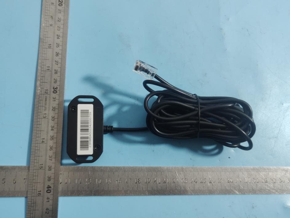
2ANPB-RCM-BT2
Feb 05, 2024BT-2 Bluetooth Module
Equipment Class
DTS - Digital Transmission System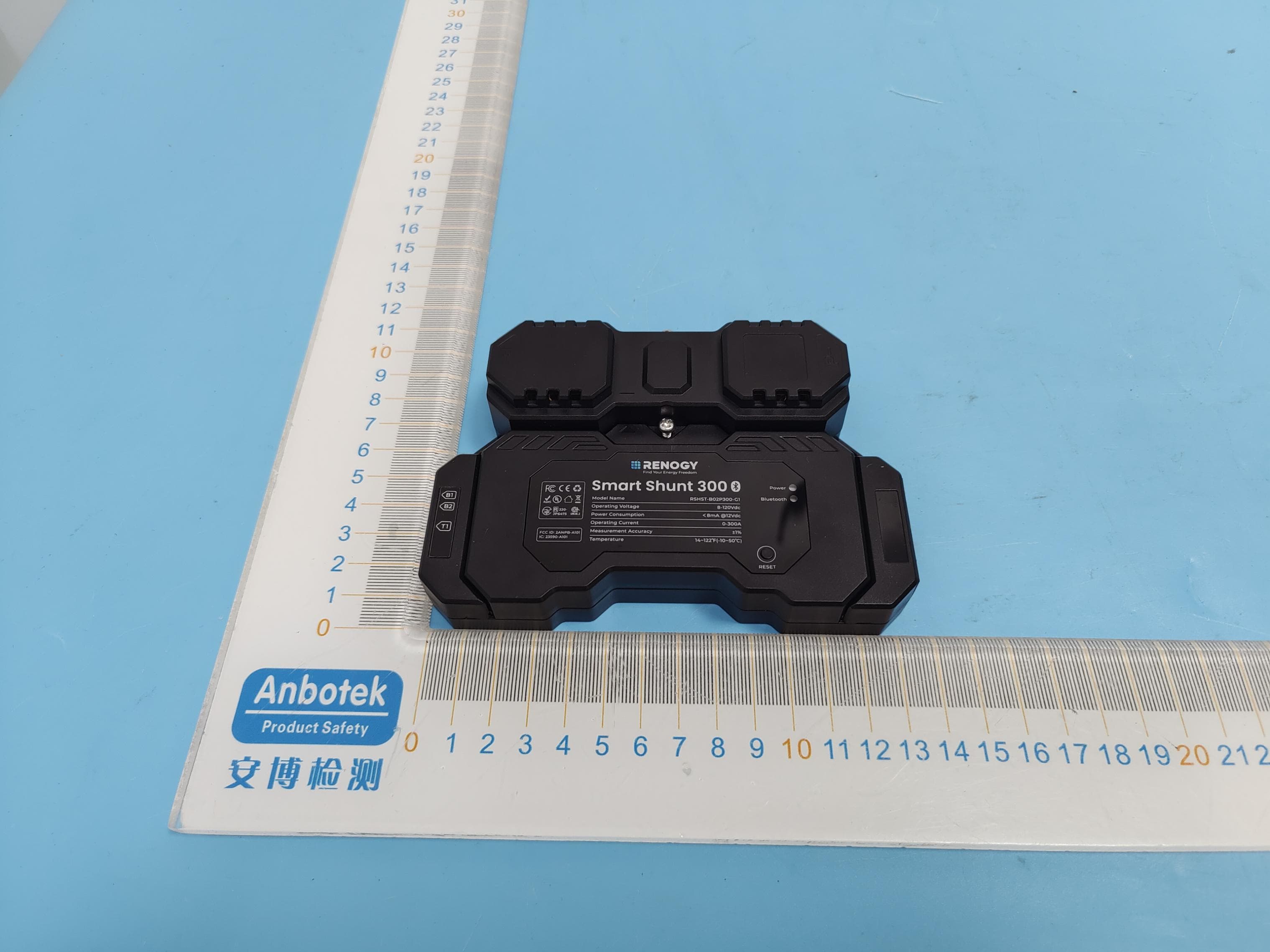
2ANPB-A101
Nov 07, 2023Smart Shunt 300
Equipment Class
DTS - Digital Transmission System
2ANPB-RBT12100LFP
Sep 04, 2023SMART LITHIUM IRON PHOSPHATE BATTERY
Equipment Class
DTS - Digital Transmission System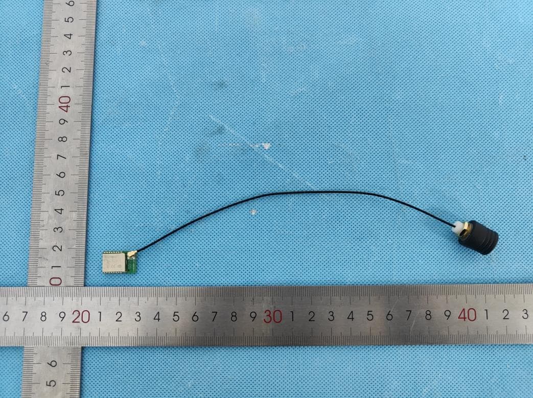
2ANPB-RIV1230RCH
Jul 17, 2023Bluetooth Communication Module
Equipment Class
DTS - Digital Transmission System
2ANPBGWSN-W02W
May 05, 2023Renogy ONE Core
Equipment Class
DTS - Digital Transmission System