2ANR7-VT66TPMS TOOL
ATEQ INSTRUMENTS (ASIA) PTE LTD.TAIWAN BRANCH (SINGAPORE)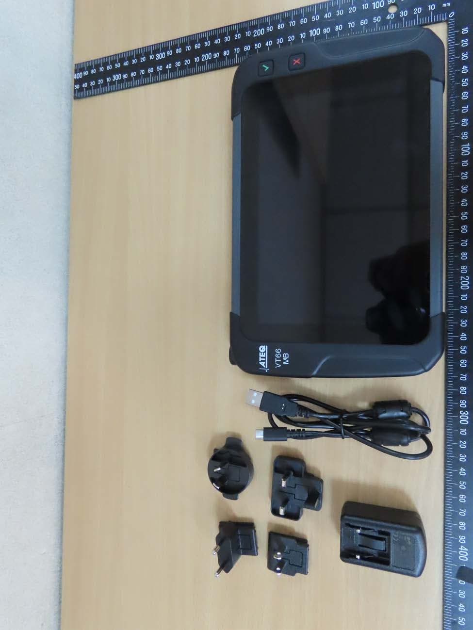
Click to zoom
Application Details
- Equipment Class
- DTS - Digital Transmission System
- Date of Grant
- Dec 22, 2020
- Application Purpose
- Original Equipment
- Date of Application
- Dec 17, 2020
- Equipment Note
- TPMS TOOL
- Frequency Range
- 2412.00000000 - 2462.00000000
- Country
- Taiwan
Documents & Files
Document Text
Text extracted from the exhibit documents filed with the FCC. Open a document above to read the original.
Users Manual
USER MANUAL ATEQ VT66MB Version 1.0 www.ateq-tpms.com Reference: UM-VT66MB-EN ATEQ VT66MB UM-VT66MB-EN ATEQ VT66MB User manual Page 2/81 1 Revision of Tool We continuously work on improving our products. This is why the information contained in this user manual, the tool and its technical specifications may be modified without notice. Edition/Revision Reference Date (week/year) Chapters updated First edition UM-VT66MB-EN 20/2020 Creation ATEQ VT66MB UM-VT66MB-EN ATEQ VT66MB User manual Page 3/81 2 Safety recommendation 2.1 Regarding electromagnetic field emission devices The VT66MB tool is a device that emits electromagnetic waves when in use: • The tool can interfere with the operation of pacemakers, • People who have pacemakers should never use the tool, • Use of and access to the tool must be controlled. No electromagnetic field is produced when the device is not transmitting. So there is no exposure during this period. Operation of the tool: • produces no harmful interference, • can be affected by any type of interference, • certain interference may cause a malfunction. 2.2 Safety information Please read this information before using the tool. • Always follow these safety instructions. • Your Tire Pressure Monitoring System (TPMS) tool has been designed to be durable, safe and reliable when properly used. • All ATEQ TPMS tools are intended to be used only by qualified and trained automotive technicians in a laboratory, or in a light industrial or repair shop environment. • If you have any questions on the safe use of this tool, please contact your local dealer. 2.2.1 Read all the instructions • All the information in this manual concerning the tool must be adhered to. • All operating instructions must be followed. 2.2.2 Keep these instructions in a safe place The safety and operating instructions should be kept in a safe place for future reference. 2.2.3 Cleaning ATEQ VT66MB UM-VT66MB-EN ATEQ VT66MB User manual Page 4/81 • Clean the tool with a soft dry cloth, or if necessary, with a soft damp cloth with clean water. • Do not use any harsh chemical solvents such as acetone, thinner, brake cleaner, alcohol, etc as this may damage the tool. 2.2.4 Water & Moisture • Do not put the tool in contact with water or any other liquid. • Never spill liquid of any kind onto the tool. 2.2.5 Storage Do not use or store the tool in an area: • exposed to direct sunlight, • subject to excessive moisture. 2.2.6 Usage • To reduce the risk of fire, do not operate the tool: o in the vicinity of flammable liquids, o in case of risk of exposure to explosive gases or vapors. • Keep the tool away from heat sources. • Do not operate the tool with the battery cover removed. • Do not position the equipment so that it is difficult to operate the disconnecting device. 2.3 Standards and references This device complies with: • CE / EN standards • Part 15 of the FCC Rules • RoHS standards 2.4 Warnings • Read the instructions before use. • Wear safety goggles (user and bystanders). • Do not use on live electrical circuits. • Risk of entanglement. Read the information on the declarations of certification and on recycling the VT66MB tool on the warranty page 69 of this user guide. ATEQ VT66MB UM-VT66MB-EN ATEQ VT66MB User manual Page 5/81 3 Description of the ATEQ VT66MB tool 3.1 Overview of the tool The ATEQ VT66MB tool is made for the servicing of TPMS 1 sensors installed in the tire assembly. The tool: • activates, reads, diagnoses TPMS sensors, • resets the vehicle's TPMS computer through the OBD-II interface, • reads RFID 2 tags that identify the tires of certain Daimler vehicles, and allows the programming of RFID Tire Data to these vehicles, • provides a catalogue of TPMS sensor spare part references, • allows programming of aftermarket sensors, for non-Daimler vehicles • checks correct operation of the Remote Keyless Entry fob. • checks tire tread depth using an optional accessory, The Tool is compatible with the following types of vehicles: o Daimler light vehicles, o Daimler trucks, o Daimler buses, o Light vehicles of other brands • The RFID 3 tags that identify the tires of certain Daimler vehicles. 1 TPMS: Tire Pressure Monitoring System. 2 RFID: Radio Frequency Identification, "contactless". 3 ATEQ VT66MB UM-VT66MB-EN ATEQ VT66MB User manual Page 6/81 3.2 Front panel LF antenna for activating TPMS sensors Confirm Button Touch screen Cancel Button ATEQ VT66MB UM-VT66MB-EN ATEQ VT66MB User manual Page 7/81 3.3 Back panel RFID antenna for reading tire RFID tags Speaker Flash light Camera lens ATEQ VT66MB UM-VT66MB-EN ATEQ VT66MB User manual Page 8/81 3.4 Top edge 3.5 Connectors The VT66MB tool integrates the following connectors: • USB C - to recharge and update the tool, • RJ45 - to connect optional accessories like the tire tread depth gauge (TTD), • OBD-II - to connect the tool to a vehicle’s OBD diagnostic socket. 3.6 Function keys ON/OFF button Confirm button USB connector OBD-II connector RJ45 connector for optional accessories Power ON/OFF ATEQ VT66MB UM-VT66MB-EN ATEQ VT66MB User manual Page 9/81 Cancel button 3.7 Product content The ATEQ VT66MB kit includes: • The tool • OBD-II cable • USB data cable • Mains power charger • EU, UK and US adapters for charger • Quick Start Guide • Transport case Optional accessories: • Tire tread depth gauge (TTD) ATEQ VT66MB UM-VT66MB-EN ATEQ VT66MB User manual Page 10/81 4 Before starting 4.1 Charging Charge the tool before using it the first time. Connect the charging cable to the mains and to the USB-C port of the tool. Be sure to charge it regularly, not to fully discharge the battery. A battery charge indicator is displayed at the top right of the screen, when the tool is switched on. The battery charge level is given as a percentage. Battery replacement: to purchase a battery replacement, please contact the point of purchase. 4.2 Turning the tool on Press the ON/OFF button for 3 seconds to power up the tool. Add start image The start image is displayed. Add th…
Text truncated - open the document above for the full version.
Cover Letter(s)
QUBE 6010 UHF RFID Antenna Specification 1Rev.0.2.0 2015-05-19 1. Part Name KSA-921A6010B100B 2. Electrical Specifications Min.TypicalMax.Unit 917921925MHz Fc ± 13Fc ± 15MHz -15dB 2.5dBic -13-10dB 1.3 80 100 degree 50 Ω -30 +70°C 14 g Note 1. Operating frequency is defined as frequency range between f3dB_low and f3dB_high. Weight Operating Temperature Item Specifications Center Frequency (= Fc) Operating Frequency Return Loss @ Operating Frequency PolarizationR.H.C.P Peak Gain @ Fc (RHCP) Gain @ Reference Antenna Axial Ratio @ Fc Beamwidth (@3dB) Impedance 2Rev.0.2.0 2015-05-19 3. Dimensions - Foot Print Tolerance Unless Otherwise Specified : ±0.2 Unit : mm KSA-921A6010B100B YYWW 6010_V1.0_ SANGSHIN 6010_V2.0 6010 U.FL or CMP 1.32Φ 100±5 3Rev.0.2.0 2015-05-19 4. S-parameter Data 4.1 Return Loss (S11) 4.2 Smith Chart (S11) 4Rev.0.2.0 2015-05-19 4.3 Gain (S21) 5Rev.0.2.0 2015-05-19 5. Antenna Chamber Data 5.1 E-Plane 5.2 H-Plane Frequency [MHz]Gain [dBic] 9060.31 891-3.75 894-3.03 897-2.26 891-3.94 9152.46 900-1.88 903-0.75 9121.97 1.76 -2.74 936 H - plane 9301.19 9330.59 9182.79 9212.68 927 894-3.18 897-2.47 9242.32 9091.26 900-1.97 -0.06 939-0.73 942-1.11 1.18 1.88 9152.33 918 945-1.59 948-2.14 951 2.63 903-0.80 9060.25 909 E - plane Frequency [MHz]Gain [dBic] 951-2.87 2.24 9271.69 912 1.14 9330.54 936-0.13 9212.59 924 948-2.23 939-0.77 942-1.15 945-1.68 930 6Rev.0.2.0 2015-05-19 5.3 Gain vs Frequency 6. Measurement Condition 6.1 S-parameter Measurement 7Rev.0.2.0 2015-05-19 6.2 Gain Measurement 8.Revision Revision No. Originator 0.2.0SM Yun Full specification Description of ChangeDate of Changes 19-May-15 8Rev.0.2.0 2015-05-19 Disclaimer: PHYCHIPS reserves the right to make changes to the information in this document without prior otice. The purchase of PHYCHIPS products does not convey any license under patent rights owned by PHYCHIPS or others. PHYCHIPS does not assume any responsibility for the use of this product. It is the customer’s sponsibility to make sure that the system complies with regulations. © 2018 PHYCHIPS Inc. All rights reserved. The reproduction of this document is NOT allowed without approval of PHYCHIPS Inc. 9.Address Information PHYCHIPS Inc. #104, 187 Techno 2-ro Yuseong-gu, Daejeon, Korea (Yongsan-dong. Migun Technoworld 2), 34025 Web site : http://www.phychips.com E-mail : [email protected] TEL : +82-42-864-2402 FAX : +82-42-864-2403 9Rev.0.2.0 2015-05-19
Cover Letter(s)
亞 驪 企 業 股 份 有 限 公 司 ARISTOTLE ENTERPRISES 承 認 申 請 書 客戶名稱: Customer 香港商磐旭智能國際股份有限公司台灣分公司 廠商料號: Part No. RFA-25-AP532-70B-45 品名: Description DB, L=45mm,IPEX 圖號: Drawing No. RFA-25-AP532-70B-45 客戶料號: Drawing No. 3422242000290M 客戶品名: 客戶規格: CBL,ANTENNA,ARISTOTLE,RFA-25-AP532-70B-45(未) 45mm,IPEX1,24*18*0.6mm,FOR GT78V WIFI/BT(AP532-BT_V1) 出廠簽章: 檢 查 TEST BY 核 對 CHECK BY 承 認 APPROVE BY 周沂珮 黃秋芳 廖煥文 承認簽章: 檢 查 TEST BY 核 對 CHECK BY 承 認 APPROVE BY 地址:新北市中和區莒光路63號8樓 電話:02-2225-8209 傳真:02-2225-7523 表單編號:QP-0603-F02 版本:A ROHS COMPLIANCE Efficiency Avg. GainPeak GainXY-planeYZ-planeZX-planeXY-planeYZ-planeZX-plane 2400.0041.46-3.823.14-4.63-5.91-2.150.12-1.753.06 2450.0043.31-3.633.50-4.39-6.10-2.010.82-1.762.66 2500.0041.98-3.773.43-4.65-6.21-2.120.59-1.462.57 5150.0065.04-1.875.63-6.31-2.79-2.39-1.314.304.91 5350.0069.98-1.555.72-5.96-2.45-1.94-1.084.655.23 5475.0067.62-1.705.82-5.89-2.43-2.16-0.875.275.49 5600.0060.81-2.166.20-6.09-2.83-2.69-0.504.764.88 5725.0066.79-1.756.48-5.70-2.42-2.370.804.735.07 5750.0069.16-1.606.68-5.50-2.13-2.231.234.905.16 5825.0070.98-1.497.18-4.95-1.92-2.192.055.195.38 5875.0071.37-1.467.22-4.67-2.06-2.382.485.105.36 V+H Peak Gain Frequency (MHz) 3D V+H Avg. Gain 測試報告 測試報告 2400 MHz 2450 MHz 2500 MHz XY Plane (+X = 0°, +Y = +90°) / Elevation = 90 ° 0 90 180 -90 -25 dB -15 dB -5 dB 5 dB YZ Plane (+Z = 0°, +Y = +90°) / Azimuth = 90 ° 0 90 180 -90 -25 dB -15 dB -5 dB 5 dB ZX Plane (+Z = 0°, +X = +90°) / Azimuth = 0 ° 0 90 180 -90 -25 dB -15 dB -5 dB 5 dB 測試報告 5150 MHz 5350 MHz 5475 MHz 5600 MHz 5725 MHz 5750 MHz 5825 MHz 5875 MHz XY Plane (+X = 0°, +Y = +90°) / Elevation = 90 ° 0 90 180 -90 -25 dB -15 dB -5 dB 5 dB YZ Plane (+Z = 0°, +Y = +90°) / Azimuth = 90 ° 0 90 180 -90 -25 dB -15 dB -5 dB 5 dB ZX Plane (+Z = 0°, +X = +90°) / Azimuth = 0 ° 0 90 180 -90 -25 dB -15 dB -5 dB 5 dB 3 NAN YA PLASTICS CORPORATION ELECTRONIC MATERIALS DIVISION. COPPER CLAD LAMINATE DEPARTMENT Glass cloth base epoxy resin NO. 201. TUNG HWA N. ROAD, flame retardant copper clad laminate TAIPEI, TAIWAN. NP-140TL FEATURES x Multi-functional epoxy renders the material outstanding x High luminance of epoxy contrast with copper for laser type A.O.I. heat resistance, better dimensional stability, and through- x UV solder mask may be applied simultaneously in order to hole reliability that benefit the performance of high layer increase yields. count multilayer boards. x HTE copper foil applied to prevent corner cracking. x IPC-4101B specification is applicable. PERFORMANCE LIST Characteristics Unit Conditioning Typical Values SPEC Test Method Volume resistivity MΩ-cm C-96/35/90 5.0 x10 9 10 6 K 2.5.17 Surface resistivity MΩ C-96/35/90 5.0 x10 7 10 4 K 2.5.17 Permittivity 1 MHZ - C-24/23/50 4.2-4.4 5.4 L 2.5.5.9 Permittivity 1 GHZ - C-24/23/50 3.8-4.0 - 2.5.5.9 Loss Tangent 1 MHZ - C-24/23/50 0.015-0.020 0.035 L 2.5.5.9 Loss Tangent 1 GHZ - C-24/23/50 0.012-0.014 - 2.5.5.9 Arc resistance SEC D-48/50+D-0.5/23 120 K 60 K 2.5.1 Dielectric breakdown KV D-48/50 60 K 40 K 2.5.6 Moisture absorption % D-24/23 0.20-0.30 0.35 L 2.6.2.1 Flammability - C-24/23/50+E-24/12594V0 94V0 UL94 Peel strength 1 oz Ib/in 288 x10” solder floating 10-14 6 K 2.4.8 Thermal stress SEC 288 solder dipping 90 K 10 K 2.4.13.1 Glass transition temp DSC 140±5 N/A 2.4.25 Dimensional stability X-Y axis % E 4/105 0.01-0.03 0.05 L 2.4.39 Coefficient of thermal expansion Z-axis before Tg Z-axis after Tg ppm/ ppm/ TMA TMA 50-70 250-350 N/A 2.4.24 NOTE: Data shown are nominal values for reference only. The average value in the table refers to samples of .020” 1/1. Test method per IPC-TM-650 4 UV TRANSMISSION CURVE OF 0.2mm CCL PRODUCT SIZE & THICKNESS THICKNESS INCH(mm) COPPER CLADDING OZ (μm) SIZE INCH mm THICKNESS TOLERANCE 0.004 (0.1) to 0.047(1.2) 0.5 (17) 1.0 (35) 2.0 (70) 48.8 x 36.6 1240 x 0930 48.8 x 40.5 1240 x 1030 48.8 x 42.5 1240 x 1080 CLASS C/M Keeping the core and prepreg in the same grain direction is crucial to ensure the flatness of multilayer boards. Grain direction is shown on the Certificate of Conformance CERTIFICATION UL x UL File No. : E98983 5 CONSTRUCTION: THICKNESS mm mil CONSTRUCTION 0.08 3 2112 1 ply 0.10 4 1080 2 plies 0.11 4 2116 1 ply 0.13 5 1080 2 plies 0.13sp 5 2116 1 ply 0.15 6 1506 1 ply 0.16 6 2112 2 plies 0.21 8 7628 1 ply 0.26 10 2116 2 plies 0.30 12 2116 3 plies 0.30sp 12 1506 2 plies 0.35 14 7628 2 plies 0.38 15 7628 2 plies *1.2,1.1,1.0,0.9,0.77 mm, THICKNESS INCLUDES CLADDING. ALL OTHERS EXCLUDE CLADDING. THICKNESS mm mil CONSTRUCTION 0.45 18 7628 x 2 + 1080 x 1 0.46 18 7667 2 plies 0.50 20 7628 3 plies 0.53 21 7628 3 plies 0.60 24 7628 3 plies 0.77 31 7628 4 plies 0.8 32 7628 4 plies 0.9 36 7628 5 plies 1.0 39 7628 5 plies 1.1 43 7628 6 plies 1.2 47 7628 6 plies SPECIFICATION FOR APPROVAL DOCUMENT: A3132TS001 STYLE: COAXIAL CABLE 105°C 30V SIZE: 32AWG×1C BRAID :TD RECOGNIZED: UL 1979 MEET VW-1 WONDERFUL HI-TECH CO.,LTD. OFFICE:72WU KONG 6TH ROAD, WU KU IND. DISTRICT TAIPEI HSIEN,TAIWAN TEL:(02)22988033 FAX:(02)22988031-2 FAC TO RY:17 PEI YUAN ROAD, CHUNG-LI IND. PARK TAIWAN, R.O.C. TEL:(03)4527777 FAX:(03)4517214 WONDERFUL HI-TECH CO., LTD. SPECIFICATION STYLE 105°C 30V UL 1979 DOCUMENT NO : A3132TS001 SIZE 32AWG ESTABLISHED DATE: Mar/16/2005 STANDARD : Size AWG 32 Material ---- Silver Cover Copper Conductors No. ---- 7 Conductors Size mm 0.085 Conductor O.D. mm 0.26 Average Thickness mm 0.22 Diameter mm 0.70 ± 0.03 Material ---- FEP Insulation Color ---- Clear Material ---- Tinned Copper Construction mm 16 / 4 / 0.050 Braid Coverage % 89.4 Average Thickness mm 0.12 Diameter mm 1.13 ± 0.05 Material ---- FEP Jacket Color ---- According to customer Marking Non Drawing AK001/210X297/1.0 PAGE : 1 EDITION : 1.4 MAKER : CONFIRM : APPROVAL : WONDERFUL HI-TECH CO., LTD. SPECIFICATION Electrical & Physical Properties Item 32AWG Rating Temp Voltage 105°C 30V Conductor Resistance 497 OHM/KM/20°C MAX. Insulation Resistance 3000 MEGA OHM-KM MIN. Dielectric Strength AC 1000 …
Text truncated - open the document above for the full version.
External Photos
Registration number: W6M22006-19965-FCC FCC ID: 2ANR7-VT66 External Photos Worldwide Testing Services(Taiwan) Co., Ltd. Appendix page 2 of 43 Registration number: W6M22006-19965-FCC FCC ID: 2ANR7-VT66 Worldwide Testing Services(Taiwan) Co., Ltd. Appendix page 3 of 43 Registration number: W6M22006-19965-FCC FCC ID: 2ANR7-VT66 Worldwide Testing Services(Taiwan) Co., Ltd. Appendix page 4 of 43 Registration number: W6M22006-19965-FCC FCC ID: 2ANR7-VT66 Worldwide Testing Services(Taiwan) Co., Ltd. Appendix page 5 of 43 Registration number: W6M22006-19965-FCC FCC ID: 2ANR7-VT66 Worldwide Testing Services(Taiwan) Co., Ltd. Appendix page 6 of 43 Registration number: W6M22006-19965-FCC FCC ID: 2ANR7-VT66 Worldwide Testing Services(Taiwan) Co., Ltd. Appendix page 7 of 43 Registration number: W6M22006-19965-FCC FCC ID: 2ANR7-VT66 Worldwide Testing Services(Taiwan) Co., Ltd. Appendix page 8 of 43 Registration number: W6M22006-19965-FCC FCC ID: 2ANR7-VT66 Worldwide Testing Services(Taiwan) Co., Ltd. Appendix page 9 of 43
Internal Photos
Registration number: W6M22006-19965-FCC FCC ID: 2ANR7-VT66 Internal Photos Worldwide Testing Services(Taiwan) Co., Ltd. Appendix page 10 of 43 Registration number: W6M22006-19965-FCC FCC ID: 2ANR7-VT66 Worldwide Testing Services(Taiwan) Co., Ltd. Appendix page 11 of 43 Registration number: W6M22006-19965-FCC FCC ID: 2ANR7-VT66 Worldwide Testing Services(Taiwan) Co., Ltd. Appendix page 12 of 43 Registration number: W6M22006-19965-FCC FCC ID: 2ANR7-VT66 Worldwide Testing Services(Taiwan) Co., Ltd. Appendix page 13 of 43 Registration number: W6M22006-19965-FCC FCC ID: 2ANR7-VT66 Worldwide Testing Services(Taiwan) Co., Ltd. Appendix page 14 of 43 Registration number: W6M22006-19965-FCC FCC ID: 2ANR7-VT66 Worldwide Testing Services(Taiwan) Co., Ltd. Appendix page 15 of 43 Registration number: W6M22006-19965-FCC FCC ID: 2ANR7-VT66 Worldwide Testing Services(Taiwan) Co., Ltd. Appendix page 16 of 43 Registration number: W6M22006-19965-FCC FCC ID: 2ANR7-VT66 Worldwide Testing Services(Taiwan) Co., Ltd. Appendix page 17 of 43 Registration number: W6M22006-19965-FCC FCC ID: 2ANR7-VT66 Worldwide Testing Services(Taiwan) Co., Ltd. Appendix page 18 of 43 Registration number: W6M22006-19965-FCC FCC ID: 2ANR7-VT66 Worldwide Testing Services(Taiwan) Co., Ltd. Appendix page 19 of 43 Registration number: W6M22006-19965-FCC FCC ID: 2ANR7-VT66 Worldwide Testing Services(Taiwan) Co., Ltd. Appendix page 20 of 43 Registration number: W6M22006-19965-FCC FCC ID: 2ANR7-VT66 Worldwide Testing Services(Taiwan) Co., Ltd. Appendix page 21 of 43 Registration number: W6M22006-19965-FCC FCC ID: 2ANR7-VT66 Worldwide Testing Services(Taiwan) Co., Ltd. Appendix page 22 of 43 Registration number: W6M22006-19965-FCC FCC ID: 2ANR7-VT66 Worldwide Testing Services(Taiwan) Co., Ltd. Appendix page 23 of 43 Registration number: W6M22006-19965-FCC FCC ID: 2ANR7-VT66 Worldwide Testing Services(Taiwan) Co., Ltd. Appendix page 24 of 43 Registration number: W6M22006-19965-FCC FCC ID: 2ANR7-VT66 Worldwide Testing Services(Taiwan) Co., Ltd. Appendix page 25 of 43 Registration number: W6M22006-19965-FCC FCC ID: 2ANR7-VT66 Worldwide Testing Services(Taiwan) Co., Ltd. Appendix page 26 of 43 Registration number: W6M22006-19965-FCC FCC ID: 2ANR7-VT66 Worldwide Testing Services(Taiwan) Co., Ltd. Appendix page 27 of 43 Registration number: W6M22006-19965-FCC FCC ID: 2ANR7-VT66 Worldwide Testing Services(Taiwan) Co., Ltd. Appendix page 28 of 43 Registration number: W6M22006-19965-FCC FCC ID: 2ANR7-VT66 Worldwide Testing Services(Taiwan) Co., Ltd. Appendix page 29 of 43
RF Exposure Info
Test Laboratory: BTL Date: 2020/9/2 System Check_H5G_20200902 Frequency: 5200 MHz; Duty Cycle: 1:1; Room Ambient Temperature: 23.0C; Liquid Temperature: 22.0C Medium parameters used: f = 5200 MHz; σ = 4.498 S/m; ε r = 35.125; ρ = 1000 kg/m 3 DASY5 Configuration: - Area Scan Setting: Find Secondary Maximum Within: 2.0 dB and with a peak SAR value greater than 0.0012W/kg - Electronics: DAE4 Sn1486; Calibrated: 2020/6/4 - Probe: EX3DV4 - SN7369; ConvF(5.13, 5.13, 5.13) @ 5200 MHz; Calibrated: 2020/5/29 - Sensor-Surface: 1.4mm (Mechanical Surface Detection) - Phantom: ELI V5.0 (20deg probe tilt); Type: QD OVA 002 AA; Serial: 1240 Configuration/Pin=100mW/Area Scan (10x10x1): Measurement grid: dx=10mm, dy=10mm Maximum value of SAR (measured) = 12.4 W/kg Configuration/Pin=100mW/Zoom Scan (7x7x12)/Cube 0: Measurement grid: dx=4mm, dy=4mm, dz=2mm Reference Value = 60.45 V/m; Power Drift = 0.10 dB Peak SAR (extrapolated) = 29.2 W/kg SAR(1 g) = 7.41 W/kg; SAR(10 g) = 2.15 W/kg Smallest distance from peaks to all points 3 dB below = 7.4 mm Ratio of SAR at M2 to SAR at M1 = 55.4% Maximum value of SAR (measured) = 18.7 W/kg 0 dB = 18.7 W/kg = 12.72 dBW/kg Test Laboratory: BTL Date: 2020/9/2 System Check_H5G_20200902 Frequency: 5800 MHz; Duty Cycle: 1:1; Room Ambient Temperature: 23.0C; Liquid Temperature: 22.0C Medium parameters used: f = 5800 MHz; σ = 5.187 S/m; ε r = 33.756; ρ = 1000 kg/m 3 DASY5 Configuration: - Area Scan Setting: Find Secondary Maximum Within: 2.0 dB and with a peak SAR value greater than 0.0012W/kg - Electronics: DAE4 Sn1486; Calibrated: 2020/6/4 - Probe: EX3DV4 - SN7369; ConvF(4.68, 4.68, 4.68) @ 5800 MHz; Calibrated: 2020/5/29 - Sensor-Surface: 1.4mm (Mechanical Surface Detection (Locations From Previous Scan Used)), Sensor- Surface: 1.4mm (Mechanical Surface Detection) - Phantom: ELI V5.0 (20deg probe tilt); Type: QD OVA 002 AA; Serial: 1240 Configuration/Pin=100mW/Area Scan (10x10x1): Measurement grid: dx=10mm, dy=10mm Maximum value of SAR (measured) = 14.2 W/kg Configuration/Pin=100mW/Zoom Scan (7x7x12)/Cube 0: Measurement grid: dx=4mm, dy=4mm, dz=2mm Reference Value = 60.65 V/m; Power Drift = 0.02 dB Peak SAR (extrapolated) = 38.9 W/kg SAR(1 g) = 8.15 W/kg; SAR(10 g) = 2.31 W/kg Smallest distance from peaks to all points 3 dB below = 7.5 mm Ratio of SAR at M2 to SAR at M1 = 48.2% Maximum value of SAR (measured) = 21.9 W/kg 0 dB = 21.9 W/kg = 13.40 dBW/kg Test Laboratory: BTL Date: 2020/9/3 System Check_H2450_20200903 Frequency: 2450 MHz; Duty Cycle: 1:1; Room Ambient Temperature: 23.0C; Liquid Temperature: 22.0C Medium parameters used (interpolated): f = 2450 MHz; σ = 1.871 S/m; ε r = 38.29; ρ = 1000 kg/m 3 DASY5 Configuration: - Area Scan Setting: Find Secondary Maximum Within: 2.0 dB and with a peak SAR value greater than 0.0012W/kg - Electronics: DAE4 Sn1486; Calibrated: 2020/6/4 - Probe: EX3DV4 - SN7369; ConvF(7.6, 7.6, 7.6) @ 2450 MHz; Calibrated: 2020/5/29 - Sensor-Surface: 1.4mm (Mechanical Surface Detection) - Phantom: ELI V5.0 (20deg probe tilt); Type: QD OVA 002 AA; Serial: 1240 System Performance Check at Frequencies above 1 GHz/Pin=250mW/Area Scan (9x9x1): Measurement grid: dx=12mm, dy=12mm Maximum value of SAR (measured) = 21.0 W/kg System Performance Check at Frequencies above 1 GHz/Pin=250mW/Zoom Scan (7x7x7)/Cube 0: Measurement grid: dx=5mm, dy=5mm, dz=5mm Reference Value = 110.2 V/m; Power Drift = -0.05 dB Peak SAR (extrapolated) = 26.5 W/kg SAR(1 g) = 12.3 W/kg; SAR(10 g) = 5.74 W/kg Smallest distance from peaks to all points 3 dB below = 11 mm Ratio of SAR at M2 to SAR at M1 = 45.1% Maximum value of SAR (measured) = 21.0 W/kg 0 dB = 21.0 W/kg = 13.22 dBW/kg
RF Exposure Info
Test Laboratory: BTL Date: 2020/9/2 WiFi-5G Frequency: 5180 MHz; Duty Cycle: 1:1; Room Ambient Temperature: 23.0C; Liquid Temperature: 22.0C Medium parameters used (interpolated): f = 5180 MHz; σ = 4.475 S/m; ε r = 35.173; ρ = 1000 kg/m 3 DASY5 Configuration: - Area Scan Setting: Find Secondary Maximum Within: 2.0 dB and with a peak SAR value greater than 0.0012W/kg - Electronics: DAE4 Sn1486; Calibrated: 2020/6/4 - Probe: EX3DV4 - SN7369; ConvF(5.13, 5.13, 5.13) @ 5180 MHz; Calibrated: 2020/5/29 - Sensor-Surface: 1.4mm (Mechanical Surface Detection) - Phantom: ELI V5.0 (20deg probe tilt); Type: QD OVA 002 AA; Serial: 1240 TPMS TOOL/Rear/802.11a/Main Ant/Ch 36/Area Scan (7x10x1): Measurement grid: dx=10mm, dy=10mm Maximum value of SAR (measured) = 1.31 W/kg TPMS TOOL/Rear/802.11a/Main Ant/Ch 36/Zoom Scan (7x7x12)/Cube 0: Measurement grid: dx=4mm, dy=4mm, dz=2mm Reference Value = 1.584 V/m; Power Drift = 0.09 dB Peak SAR (extrapolated) = 1.96 W/kg SAR(1 g) = 0.607 W/kg; SAR(10 g) = 0.240 W/kg Smallest distance from peaks to all points 3 dB below = 11.8 mm Ratio of SAR at M2 to SAR at M1 = 57.6% Maximum value of SAR (measured) = 1.30 W/kg Test Laboratory: BTL Date: 2020/9/2 WiFi-5G Frequency: 5765 MHz; Duty Cycle: 1:1; Room Ambient Temperature: 23.0C; Liquid Temperature: 22.0C Medium parameters used (interpolated): f = 5765 MHz; σ = 5.147 S/m; ε r = 33.832; ρ = 1000 kg/m 3 DASY5 Configuration: - Area Scan Setting: Find Secondary Maximum Within: 2.0 dB and with a peak SAR value greater than 0.0012W/kg - Electronics: DAE4 Sn1486; Calibrated: 2020/6/4 - Probe: EX3DV4 - SN7369; ConvF(4.68, 4.68, 4.68) @ 5765 MHz; Calibrated: 2020/5/29 - Sensor-Surface: 1.4mm (Mechanical Surface Detection (Locations From Previous Scan Used)), Sensor- Surface: 1.4mm (Mechanical Surface Detection) - Phantom: ELI V5.0 (20deg probe tilt); Type: QD OVA 002 AA; Serial: 1240 TPMS TOOL/Rear/802.11a/Main Ant/Ch 153/Area Scan (7x10x1): Measurement grid: dx=10mm, dy=10mm Maximum value of SAR (measured) = 2.31 W/kg TPMS TOOL/Rear/802.11a/Main Ant/Ch 153/Zoom Scan (7x7x12)/Cube 0: Measurement grid: dx=4mm, dy=4mm, dz=2mm Reference Value = 0.9070 V/m; Power Drift = 0.16 dB Peak SAR (extrapolated) = 3.37 W/kg SAR(1 g) = 0.874 W/kg; SAR(10 g) = 0.337 W/kg Smallest distance from peaks to all points 3 dB below = 12.5 mm Ratio of SAR at M2 to SAR at M1 = 50.8% Maximum value of SAR (measured) = 2.00 W/kg Test Laboratory: BTL Date: 2020/9/3 WiFi-2.4G Frequency: 2462 MHz; Duty Cycle: 1:1; Room Ambient Temperature: 23.0C; Liquid Temperature: 22.0C Medium parameters used (interpolated): f = 2462 MHz; σ = 1.885 S/m; ε r = 38.238; ρ = 1000 kg/m 3 DASY5 Configuration: - Area Scan Setting: Find Secondary Maximum Within: 2.0 dB and with a peak SAR value greater than 0.0012W/kg - Electronics: DAE4 Sn1486; Calibrated: 2020/6/4 - Probe: EX3DV4 - SN7369; ConvF(7.6, 7.6, 7.6) @ 2462 MHz; Calibrated: 2020/5/29 - Sensor-Surface: 1.4mm (Mechanical Surface Detection) - Phantom: ELI V5.0 (20deg probe tilt); Type: QD OVA 002 AA; Serial: 1240 TPMS TOOL/Rear/802.11b/Main Ant/Ch 11/Area Scan (6x8x1): Measurement grid: dx=12mm, dy=12mm Maximum value of SAR (measured) = 0.118 W/kg TPMS TOOL/Rear/802.11b/Main Ant/Ch 11/Zoom Scan (7x7x7)/Cube 0: Measurement grid: dx=5mm, dy=5mm, dz=5mm Reference Value = 0.7040 V/m; Power Drift = 0.17 dB Peak SAR (extrapolated) = 0.149 W/kg SAR(1 g) = 0.070 W/kg; SAR(10 g) = 0.032 W/kg Smallest distance from peaks to all points 3 dB below = 9.5 mm Ratio of SAR at M2 to SAR at M1 = 46.3% Maximum value of SAR (measured) = 0.119 W/kg
RF Exposure Info
Asset No.: E-434 Model No.: D2450V2 Serial No.: 973 Environmental 23.5°C, 53 % Original Cal. Date: September 21, 2018 Next Cal. Date: September 20, 2021 1IEEE Std 1528-2013 2IEC 62209-2 3KDB865664 Equipment:Manufacturer:Model No.:Serial No.:Cal.Organization:Cal. Date: Power AmplifierMini-CircuitsZHL-42W+QA1333003NAMarch 8, 2019 DC SourcelteckOT6154M00157NASpectember 31, 2019 Power MeterAnritsuML2495A1128008NADecember 5, 2019 Power SensorAnritsuMA2411B1126001NADecember 5, 2019 Power MeterAnritsuML2487A6K00004714NAJune 20, 2019 Power SensorAnritsuMA2491A1725282NAJune 20, 2019 Dual directional couplerWokenTS-PCC0M-05107090019NAMarch 10, 2019 Signal GeneratorR & SN5172BMY56200462NAApril 22, 2019 ENA Network AnalyzerAgilentE5071CMY46524658 NA March 16, 2019 Model No ItemOriginak Cal. ResultVerified on 2019/12/3DeviationResult Impedance, transformed to feed point 52.9Ω+2.01jΩ51.869Ω+1.09jΩ<5ΩPass Return Loss(dB)-29.3-27.192-7.2%Pass SAR Value for 1g(mW/g) 13.112.9-1.5%Pass SAR Value for 10g(mW/g) 6.125.99-2.1%Pass ItemOriginak Cal. ResultVerified on 2019/12/3DeviationResult Impedance, transformed to feed point 49.9Ω+4.38jΩ48.100Ω+5.29jΩ<5ΩPass Return Loss(dB)-27.2-24.913-8.4%Pass SAR Value for 1g(mW/g) 12.813.12.3%Pass SAR Value for 10g(mW/g) 5.936.123.2%Pass SAR Measurement Requirements for 100 MHz to 6 GHz Equipment Information For Head Tissue D2450V2For Body Tissue Dipole Internal Calibration Record Standard List IEEE Recommended Practice for Determining the Peak Spatial-Averaged Specific Absorpiton Rate(SAR) in the Human Head from Wireless Communication Devices: Measurement Texhniques, June 2013 Procedure to determine the Specific Absorption Rate (SAR) for wireless communication devices used in close proximity to the human body(frequency range of 30 MHz to 6 GHz), March 2010 Impedance Test-HeadReturn Loss-Head Calibrator:Approver: Validation Report for Head TSLValidation Report for Body TSL Impedance Test-BodyReturn Loss-Body
RF Exposure Info
Asset No.: E-436 Model No.: D5GHzV2 Serial No.: 1221 Environmental 22.3°C, 55 % Original Cal. Date: June 20, 2018 Next Cal. Date: June 20, 2021 1IEEE Std 1528-2013 2IEC 62209-2 3KDB865664 Equipment:Manufacturer:Model No.:Serial No.:Cal.Organization:Cal. Date: Power AmplifierMini-CircuitsZVE-8G+520701341NAMarch 9, 2018 DC SourcelteckOT6154M00157NAOctober 12, 2018 P-series power meterAgilentN1911AMY45100473NAAugust 11, 2018 wideband power sensorAgilentN1921AMY51100041NAAugust 11, 2018 power MeterAnritsuML2495A1128009NAMar. 11, 2018 Pulse Power SensorAnritsuMA 2411B1027500NAMar. 11, 2018 Dual directional couplerWokenTS-PCC0M-05107090019NAMar. 11, 2018 MXG Analog Signal Generato r AgilentN5181AMY49060710NAAugust 11, 2018 ENA Network AnalyzerAgilentE5071CMY46102965NAMarch 11, 2018 ItemOriginak Cal. Result Verified on 2018/12/25DeviationResult Impedance, transformed to feed point 53.5Ω-8.96jΩ56.5Ω-6.47jΩ<5ΩPass Return Loss(dB)-20.7-24.819.8%Pass SAR Value fo r 1g(mW/g) 7.57.27-3.1%Pass SAR Value fo r 10g(mW/g) 2.162.07-4.2%Pass Impedance, transformed to feed point 50.1Ω-3jΩ49.6Ω-2.8jΩ<5ΩPass Return Loss(dB)-30.5-30.70.7%Pass SAR Value fo r 1g(mW/g) 7.667.34-4.2%Pass SAR Value fo r 10g(mW/g) 2.22.07-5.9%Pass Impedance, transformed to feed point 51.4Ω-5.39jΩ50.2Ω-3.01jΩ<5ΩPass Return Loss(dB)-25.2-28.814.3%Pass SAR Value fo r 1g(mW/g) 8.088.323.0%Pass SAR Value fo r 10g(mW/g) 2.32.331.3%Pass Impedance, transformed to feed point 57.5Ω-2.95jΩ54.9Ω-1.65jΩ<5ΩPass Return Loss(dB)-22.5-25.814.7%Pass SAR Value fo r 1g(mW/g) 7.857.84-0.1%Pass SAR Value fo r 10g(mW/g) 2.252.2-2.2%Pass Impedance, transformed to feed point 54.5Ω-1.38jΩ55.2Ω+1.97jΩ<5ΩPass Return Loss(dB)-26.9-26.1-3.0%Pass SAR Value fo r 1g(mW/g) 7.787.891.4%Pass SAR Value fo r 10g(mW/g) 2.212.210.0%Pass SAR Measurement Requirements for 100 MHz to 6 GHz Equipment Information For Head Tissue D5GHzV2(5.2GHz) D5GHzV2(5.3GHz) Model No Dipole Internal Calibration Record Standard List IEEE Recommended Practice for Determining the Peak Spatial-Averaged Specific Absorpiton Rate(SAR) in the Human Head from Wireless Communication Devices: Measurement Texhniques, June 2013 Procedure to determine the Specific Absorption Rate (SAR) for wireless communication devices used in close proximity to the human body(frequency range of 30 MHz to 6 GHz), March 2010 D5GHzV2(5.5GHz) D5GHzV2(5.6GHz) D5GHzV2(5.8GHz) ItemOriginak Cal. Result Verified on 2018/12/25DeviationResult Impedance, transformed to feed point 53.1Ω-7.52jΩ55.1Ω-7.96jΩ<5ΩPass Return Loss(dB)-22.1-26.118.1%Pass SAR Value fo r 1g(mW/g) 6.997.284.1%Pass SAR Value fo r 10g(mW/g) 1.922.067.3%Pass Impedance, transformed to feed point 49.3Ω-2.06jΩ52.7Ω-1.73jΩ<5ΩPass Return Loss(dB)-33.1-30.3-8.5%Pass SAR Value fo r 1g(mW/g) 7.257.16-1.2%Pass SAR Value fo r 10g(mW/g) 2.042-2.0%Pass I…
Text truncated - open the document above for the full version.
Contact Information
Applicant
Roger LIN
Technical Contact
Worldwide Testing Services (Taiwan) Co., Ltd.Danny Sung
[email protected]886-2-6606-8877
6F., No.58, Lane 188, Ruey Kuand Rd., · Taiwan
Non-Technical Contact
Worldwide Testing Services (Taiwan) Co., Ltd.Rita Lin
[email protected]886-2-6606-8877
Test Firm
Worldwide Testing Services (Taiwan) Co., Ltd.Rex Kao
Technical Specifications
| # | Rule Parts | Frequency Range | Power Output |
|---|---|---|---|
| 2 | 15C | 2.41 GHz - 2.46 GHz | 42.00 mW |
Other Applications from ATEQ INSTRUMENTS (ASIA) PTE LTD.TAIWAN BRANCH (SINGAPORE)
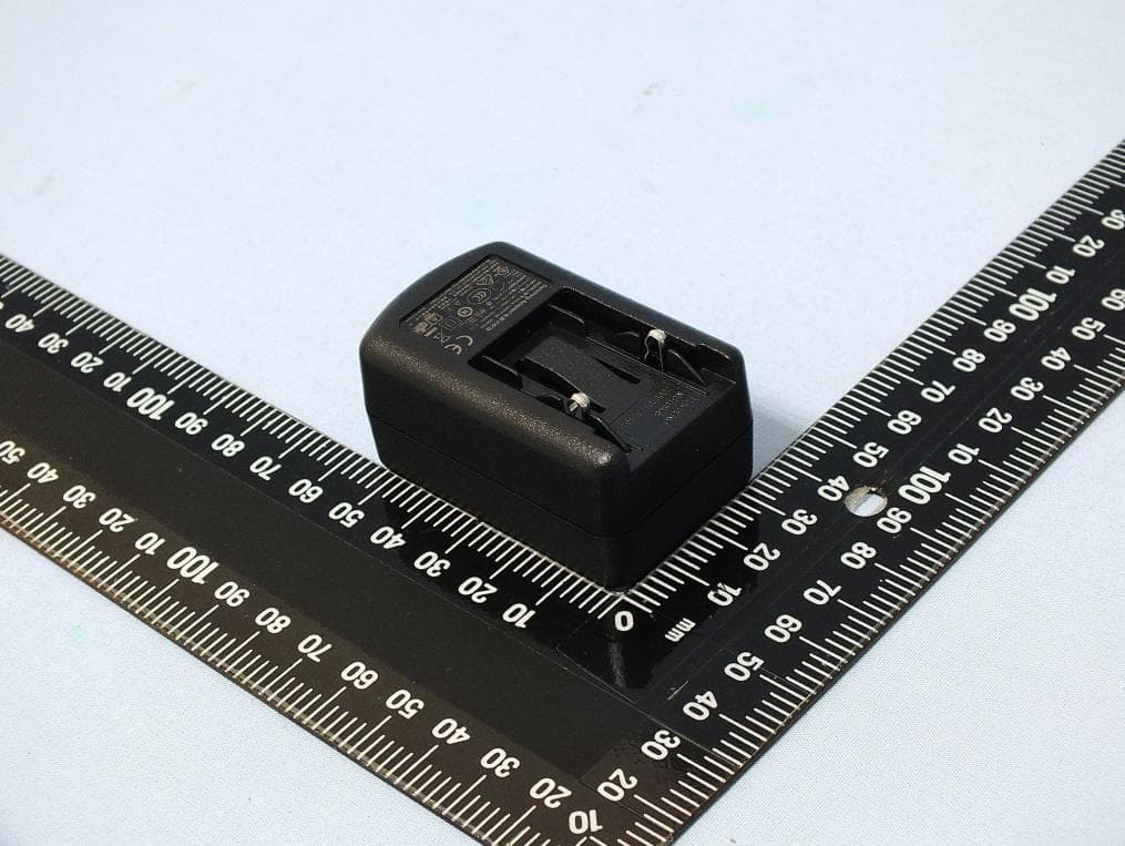
2ANR7-TPA300
Feb 24, 2020Tire-Pressure Monitoring System
Equipment Class
DCD - Part 15 Low Power Transmitter Below 1705 kHz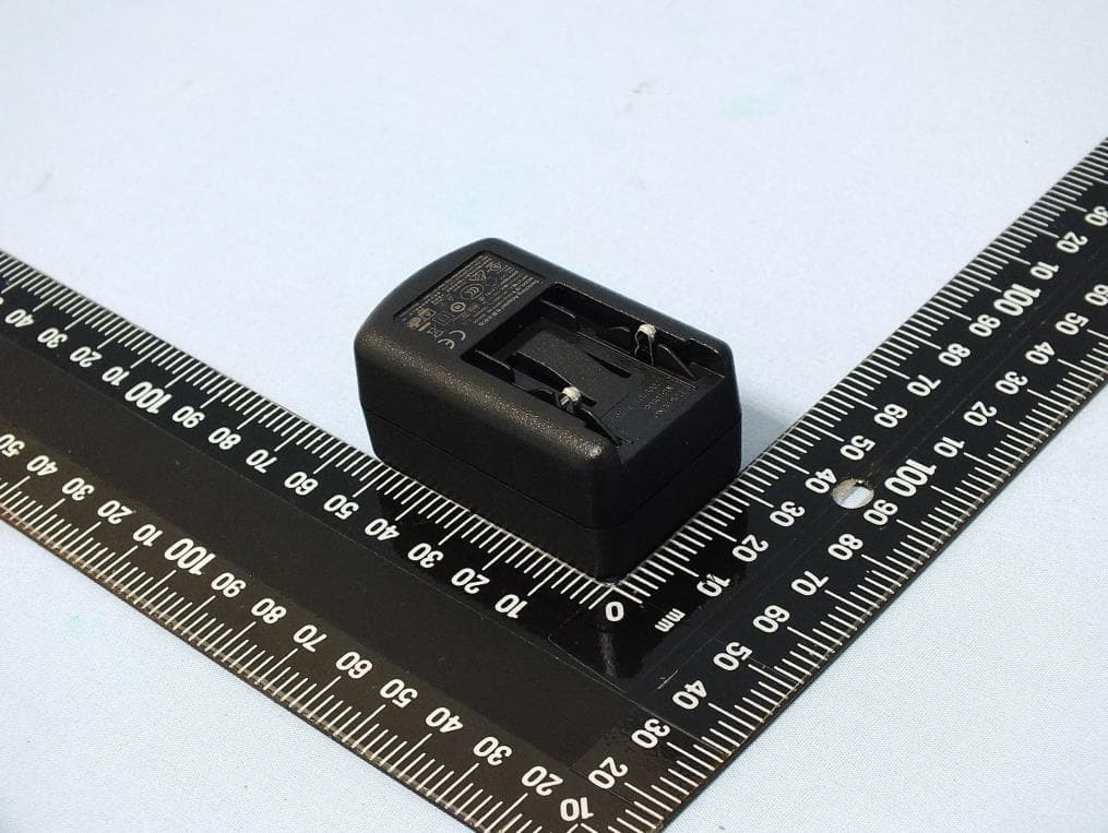
2ANR7-T56011
Feb 09, 2020Tire-Pressure Monitoring System
Equipment Class
DCD - Part 15 Low Power Transmitter Below 1705 kHz