2ANTCZG2322MWireless Camera
Ansjer Electronics Co., Ltd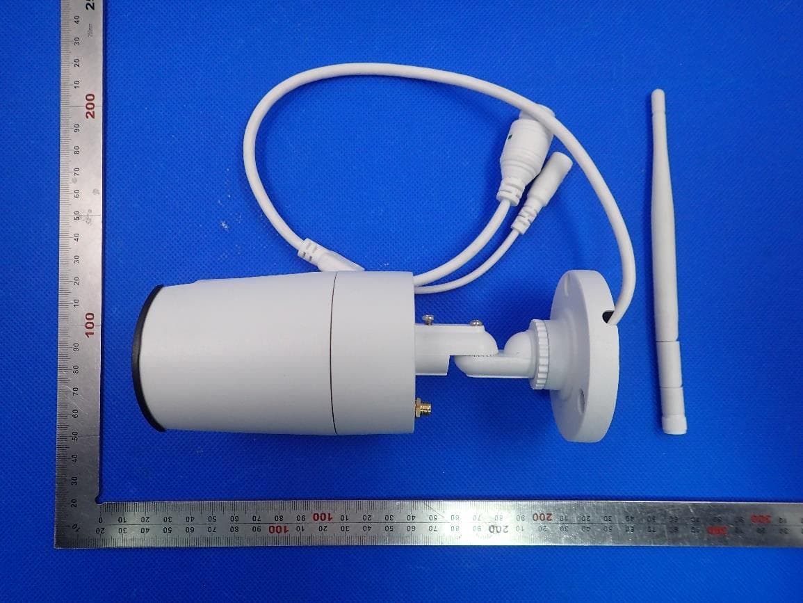
Click to zoom
Application Details
- Equipment Class
- DTS - Digital Transmission System
- Date of Grant
- Apr 24, 2020
- Application Purpose
- Original Equipment
- Date of Application
- Apr 24, 2020
- Equipment Note
- Wireless Camera
- Frequency Range
- 2412.00000000 - 2462.00000000
- Company
- Ansjer Electronics Co., Ltd
- Country
- China
Documents & Files
Document Text
Text extracted from the exhibit documents filed with the FCC. Open a document above to read the original.
Users Manual
Quick Start Guide Wireless Smart IP Camera DIY Do-It-Yourself ACCloud iOSAndroid FCC Warning This device complies with Part 15 of the FCC Rules: Operation is subject to the following two conditions: 1. This device may not cause harmful interference and 2. This device must accept any interference that is received, including any interfer ence that may cause undesired operation. Manufacturer: Ansjer Electronics Co., Ltd RF exposure warning : This equipment complies with FCC radiation exposure limits set forth for an uncontrolled environment. This equipment shall be installed and operated with minimum distance 20cm between the radiator & body. This device is acting as slave and operating in the 2.4 GHz (2412 ~2462 MHz) band. Ad Hoc function is supported but not able to operate on non-US frequencies. Do not use the device with the environment which below minimum -30 or maximum over 50 . NOTE: This equipment has been tested and found to comply with the limits for a Class B digital device, pursuant to part 15 of the FCC Rules. These limits are designed to provide reasonable protection against harmful interference in a residential installation. This equipment generates uses and can radiate radio frequency energy and, if not installed and used in accordance with the instructions, may cause harmful interference to radio communications. However, there is no guarantee that interference will not occur in a particular installation. If this equipment does cause harmful interference to radio or television reception, which can be determined by turning the equipment off and on, the user is encouraged to try to correct the interference by one or more of the following measures: - Reorient or relocate the receiving antenna. - Increase the separation between the equipment and receiver. -Connect the equipment into an outlet on a circuit different from that to which the receiver is connected. -Consult the dealer or an experienced radio/TV technician for help Changes or modifications not expressly approved by the party responsible for compliance could void the user's authority to operate the equipment. NB: This instruction takes android App as an example,iOS App is a slightly difference Scan the QR Code or search ACCloud (in App store or Google play) to download the free app, install it on smart phone ● Start the mobile app “ACCloud” ● Click “Register ” in the bottom of interface ● Enter phone number to get validation code, click Next to enter email box, password, then save it. NB: 1.Register by mobile phone number can get validation code automatically, while need to get into Email box to find code if register by email box. 2.Email box is used to retrive password when it is forgotten. Personal Account Registration Login InterfaceRegistrationLogin Password Setting ACCloudiOSAndroid Smartphone Remote Monitoring Download App Login the app, get into the main interface (My Device), click + to add device, 4 different options of device addition are available. My DeviceSelect Addition MethodWifi Smart link 1. WiFi Smartlink NB: All wireless cameras have to be connected to network via WiFi Smartlink for the first time.Do it as following steps, ● Turn on smart phone WiFi signal switch, and make it be connected to network ● Connect camera with power supply and wait for about 40 Seconds until ready to connect ● Login the App, select the device type (IP Camera or PTZ IP Camera) ● Click WiFi Smartlink, enter WiFi network password and start config (it can be configurated and connection succeed in 20-40 seconds) ● Returned to the interface of Add Device(if connection succeed), enter camera password (Default: admin), camera --- name ● Click “√√” in the upper right corner to save 2. Manual Addition NB: only working when camera has been connected to network via WiFi Smartlink ● Choose device type (IP Camera or PTZ IP Camera) ● Enter Device ID by manual(or scan UID QR code) ● Enter Password (Default: admin), device name ● Click “√ ” in the upper right corner to save Add Device 3. Local Search NB: only working when camera has been connected to network via WiFi Smartlink ● Choose device type (IP Camera or PTZ IP Camera) ● Turn on mobile phone WiFi setting, make it connect with the same LAN as Camera’s ● Click Local Search, Device ID will be displayed in a few seconds ● Choose the intended ID to add ● Enter password (Default: admin), Device name ● Click “√ ” in the upper right corner to save 4. RJ45 Cable Connection NB: only working for outdoor bullet camera (with RJ45 Connector) ● Connect bullet camera with Router via RJ45 Cable ● Choose device type on App (IP Camera or PTZ IP Camera) ● Enter camera ID (by manual), password (Default: admin) and device name ● Click “√√” in the upper right corner to save 1. App Information ● Change password: change app login password ● Update App: update your app to the latest version ● Fingerprint login: no need to enter password if fingerprint touch function is available in your phone 2. Device Information ● Click to display QR Code of device UID ( in the left bottom conner) ● Video: Click to start recording or stop recording ● Screen Shot: Click to catch photo ● Event Playback: Records playback, (Motion detection video or full time video) ● SD/HD: Change video resolution(Standard Definition,High Definition) ● Intercom: Dual-Way talk if device support(Outdoor bullet camera does not support this ) NB: Screen touch is able to control direction moving if PTZ IP camera is connected 3. Device System Setting ● Change Password: Change the device password on App, the default password is admin ● Video Setting: Choose recording mode, switch off, Full time recording or Alarm Recording ● Alarm Setting: Motion switch on or off, and change motion detection sensitivity number ● SD Card Format: Indicates storage space and delete records ● Update Online: Click to update the camera firmware if new version is available ● Alarm Push Notification: Switch on to receive reminding message App Function Introduction My Profil…
Text truncated - open the document above for the full version.
External Photos
External Photos ALL VIEW OF EUT TOP VIEW OF EUT WIFI Antenna BOTTOM VIEW OF EUT FRONT VIEW OF EUT BACK VIEW OF EUT LEFT VIEW OF EUT RIGHT VIEW OF EUT
ID Label/Location Info
FCC ID Label Location FCC ID: 2ANTCZG2322M This device complies with Part 15 of the FCC Rules. Operation is subject to the following two conditions: (1) this device may not cause harmful interference, and (2) this device must accept any interference received, including interference that may cause undesired operation.
Internal Photos
Internal Photos OPEN VIEW OF EUT-1 OPEN VIEW OF EUT-2 INTERNAL VIEW OF EUT-1 INTERNAL VIEW OF EUT-2 INTERNAL VIEW OF EUT-3 INTERNAL VIEW OF EUT-4 INTERNAL VIEW OF EUT-5 INTERNAL VIEW OF EUT-6 INTERNAL VIEW OF EUT-7 INTERNAL VIEW OF EUT-8 INTERNAL VIEW OF EUT-9 INTERNAL VIEW OF EUT-10
Operational Description
Declaration concerning Antenna Specification It is hereby declared that the product Model No.: ZG2322M, C115W4, C190W4, C199W4, C115W4FF, C190W4FF, C199W4FF, C101W4FF, C301W4FF, ZG2352M, ZG2622MW, ZG2622FW, ZNC1902FM, ZNC1902FW, ZNC1992FM, ZNC1992FW, 89002, 89003, 89004, 89012, 89007T, 89009T, 99002, 99003, 99004, 99012, 99007T, 99009T FCC ID: 2ANTCZG2322M fulfills the requirement in FCC test relating to the antenna type. The device specified above confirms to the FCC recommendations for external antenna type(s) described below: Type of antenna: Dedicated Antenna Gain of the antenna: 3dBi Frequency range: 2.412 GHz~2.462GHz The mounting of the antenna is fixed to the radio module and no other antenna should be used. Company name: Ansjer Electronics Co., Ltd Address: 301# , 1st Building,No.21 Yongtian Road, Xiangzhou 519000, Zhuhai, Guangdong, China Place: Zhuhai Date: 2020-04-13 Signature:
RF Exposure Info
RF EXPOSURE EVALUATION 1. PRODUCT INFORMATION Product Description Wireless Camera Model Name ZG2322M FCC ID 2ANTCZG2322M 2. EVALUATION METHOD AND LIMIT Human exposure to RF emissions from mobile devices (47 CFR §2.1091) may be evaluated based on the MPE limits adopted by the FCC for electric and magnetic field strength and/or power density, as appropriate, since exposures are assumed to occur at distances of 20 cm or more from persons. LIMITS FOR GENERAL POPULATION / UNCONTROLLED EXPOSURE Frequency Range (MHz) E-field Strength (E) (V/m) Magnetic Field Strength (H) (A/m) Power Density (S) (mW/cm 2 ) Averaging Time |E| 2 , |H| 2 or S (Minutes) 0.3 -- 1.34 614 1.63 (100)* 30 1.34 -- 30 824/f 2.19/f (180/f 2 )* 30 30 -- 300 27.5 0.073 0.2 30 300 -- 1500 -- -- f/1500 30 1500 -- 100,000 -- -- 1.0 30 *Note: 1. f= Frequency in MHz * Plane-wave Equivalent Power Density 2. The averaging time for General Population/Uncontrolled exposure to fixed transmitters is not applicable for mobile and portable transmitters. See 47 CFR §§2.1091 and 2.1093 on source-based time-averaging requirement for mobile and portable transmitters. S=PG/4πR² Where: S=power density P=power input to antenna G=power gain of the antenna in the direction of interest relative to an isotropic radiator R=distance to the center of radiation of the antenna 3. CALCULATION A minimum test separation distance ≥ 20 cm is required between the antenna and radiating structures of the device and nearby persons to apply mobile device exposure limits. The distance must be at least 20 cm and fully supported by the operating and installation configurations of the transmitter and its antenna(s), according to the source-based time-averaged maximum power requirements of § 2.1091(d)(2). In cases where cable losses or other attenuations are applied to determine compliance, the most conservative operating configurations and exposure conditions must be evaluated. WIFI PART(Can not transmit at different band simultaneously ) Antenna Gain=3dBi (Numeric 1.99), π=3.14 802.11b Single mode(Worst case) Note: 1. Only the worst case recorded. 2. The WIFI can transmit simultaneously. Frequency Output Power Output Power Power Density Power Density Limit MHz dBm mW mW/cm 2 mW/cm 2 2412 13.69 23.39 0.009 1
Test Report
Page 1 of 91 Report No.: AGC06662200202FE05 FCC ID : 2ANTCZG2322M APPLICATION PURPOSE : Original Equipment PRODUCT DESIGNATION : Wireless Camera BRAND NAME : N/A MODEL NAME : ZG2322M, C115W4, C190W4, C199W4, C115W4FF, C190W4FF, C199W4FF, C101W4FF, C301W4FF, ZG2352M, ZG2622MW, ZG2622FW, ZNC1902FM, ZNC1902FW, ZNC1992FM, ZNC1992FW, 89002, 89003, 89004, 89012, 89007T, 89009T, 99002, 99003, 99004, 99012, 99007T, 99009T APPLICANT : Ansjer Electronics Co., Ltd DATE OF ISSUE : Apr. 10, 2020 STANDARD(S) TEST PROCEDURE(S) : FCC Part 15.247 REPORT VERSION : V1.0 Attestation of Global Compliance (Shenzhen) Co., Ltd CAUTION: This report shall not be reproduced except in full without the written permission of the test laboratory and shall not be quoted out of context. FCC Test Report Report No.: AGC06662200202FE05 Page 2 of 91 REPORT REVISE RECORD Report Version Revise Time Issued Date Valid Version Notes V1.0 / Apr. 10, 2020 Valid Initial Release Report No.: AGC06662200202FE05 Page 3 of 91 TABLE OF CONTENTS 1. VERIFICATION OF CONFORMITY ............................................................................................................... 5 2. GENERAL INFORMATION ............................................................................................................................ 6 2.1. PRODUCT DESCRIPTION ..................................................................................................................... 6 2.2. TABLE OF CARRIER FREQUENCYS ..................................................................................................... 6 2.3. IEEE 802.11N MODULATION SCHEME .................................................................................................. 7 2.4. RELATED SUBMITTAL(S) / GRANT (S) .................................................................................................. 7 2.5. TEST METHODOLOGY .......................................................................................................................... 7 2.6. SPECIAL ACCESSORIES ....................................................................................................................... 7 2.7. EQUIPMENT MODIFICATIONS .............................................................................................................. 7 3. MEASUREMENT UNCERTAINTY ................................................................................................................. 8 4. DESCRIPTION OF TEST MODES ................................................................................................................. 9 5. SYSTEM TEST CONFIGURATION ............................................................................................................. 10 5.1. CONFIGURATION OF EUT SYSTEM ................................................................................................... 10 5.2. EQUIPMENT USED IN EUT SYSTEM ................................................................................................... 10 5.3. SUMMARY OF TEST RESULTS ............................................................................................................ 10 6. TEST FACILITY ........................................................................................................................................... 11 7. OUTPUT POWER ........................................................................................................................................ 12 7.1. MEASUREMENT PROCEDURE ........................................................................................................... 12 7.2. TEST SET-UP (BLOCK DIAGRAM OF CONFIGURATION) ................................................................... 12 7.3. LIMITS AND MEASUREMENT RESULT ............................................................................................... 13 8. 6 DB BANDWIDTH ...................................................................................................................................... 15 8.1. MEASUREMENT PROCEDURE ........................................................................................................... 15 8.2. TEST SET-UP (BLOCK DIAGRAM OF CONFIGURATION) ................................................................... 15 8.3. LIMITS AND MEASUREMENT RESULTS ............................................................................................. 16 9. CONDUCTED SPURIOUS EMISSION ........................................................................................................ 24 9.1. MEASUREMENT PROCEDURE ........................................................................................................... 24 9.2. TEST SET-UP (BLOCK DIAGRAM OF CONFIGURATION) ................................................................... 24 9.3. MEASUREMENT EQUIPMENT USEDJN ............................................................................................. 24 9.4. LIMITS AND MEASUREMENT RESULT ............................................................................................... 24 Report No.: AGC06662200202FE05 Page 4 of 91 10. MAXIMUM CONDUCTED OUTPUT POWER SPECTRAL DENSITY ....................................................... 43 10.1 MEASUREMENT PROCEDURE .......................................................................................................... 43 10.2 TEST SET-UP (BLOCK DIAGRAM OF CONFIGURATION) .................................................................. 43 10.3 MEASUREMENT EQUIPMENT USED ................................................................................................. 43 10.4 LIMITS AND MEASUREMENT RESULT .............................................................................................. 43 11. RADIATED EMISSION ............................................................................................................................... 51 11.1. MEASUREMENT PROCEDURE ...............................................................................…
Text truncated - open the document above for the full version.
Test Report
Report No.: AGC06662200202FE05 Page 61 of 91 EUT Wireless Camera Model Name ZG2322M Temperature 25°C Relative Humidity 55.4% Pressure 960hPa Test Voltage Normal Voltage Test Mode 802.11b with data rate 1 2412MHZ Antenna Vertical PK AV RESULT: PASS Report No.: AGC06662200202FE05 Page 62 of 91 EUT Wireless Camera Model Name ZG2322M Temperature 25°C Relative Humidity 55.4% Pressure 960hPa Test Voltage Normal Voltage Test Mode 802.11b with data rate 1 2462MHZ Antenna Horizontal PK AV RESULT: PASS Report No.: AGC06662200202FE05 Page 63 of 91 EUT Wireless Camera Model Name ZG2322M Temperature 25°C Relative Humidity 55.4% Pressure 960hPa Test Voltage Normal Voltage Test Mode 802.11b with data rate 1 2462MHZ Antenna Vertical PK AV RESULT: PASS Report No.: AGC06662200202FE05 Page 64 of 91 EUT Wireless Camera Model Name ZG2322M Temperature 25°C Relative Humidity 55.4% Pressure 960hPa Test Voltage Normal Voltage Test Mode 802.11g with data rate 6 2412MHZ Antenna Horizontal PK AV RESULT: PASS Report No.: AGC06662200202FE05 Page 65 of 91 EUT Wireless Camera Model Name ZG2322M Temperature 25°C Relative Humidity 55.4% Pressure 960hPa Test Voltage Normal Voltage Test Mode 802.11g with data rate 6 2412MHZ Antenna Vertical PK AV RESULT: PASS Report No.: AGC06662200202FE05 Page 66 of 91 EUT Wireless Camera Model Name ZG2322M Temperature 25°C Relative Humidity 55.4% Pressure 960hPa Test Voltage Normal Voltage Test Mode 802.11g with data rate 6 2462MHZ Antenna Horizontal PK AV RESULT: PASS Report No.: AGC06662200202FE05 Page 67 of 91 EUT Wireless Camera Model Name ZG2322M Temperature 25°C Relative Humidity 55.4% Pressure 960hPa Test Voltage Normal Voltage Test Mode 802.11g with data rate 6 2462MHZ Antenna Vertical PK AV RESULT: PASS Report No.: AGC06662200202FE05 Page 68 of 91 EUT Wireless Camera Model Name ZG2322M Temperature 25°C Relative Humidity 55.4% Pressure 960hPa Test Voltage Normal Voltage Test Mode 802.11n 20 with data rate 6.5 2412MHZ Antenna Horizontal PK AV RESULT: PASS Report No.: AGC06662200202FE05 Page 69 of 91 EUT Wireless Camera Model Name ZG2322M Temperature 25°C Relative Humidity 55.4% Pressure 960hPa Test Voltage Normal Voltage Test Mode 802.11n 20 with data rate 6.5 2412MHZ Antenna Vertical PK AV RESULT: PASS Report No.: AGC06662200202FE05 Page 70 of 91 EUT Wireless Camera Model Name ZG2322M Temperature 25°C Relative Humidity 55.4% Pressure 960hPa Test Voltage Normal Voltage Test Mode 802.11n 20 with data rate 6.5 2462MHZ Antenna Horizontal PK AV RESULT: PASS Report No.: AGC06662200202FE05 Page 71 of 91 EUT Wireless Camera Model Name ZG2322M Temperature 25°C Relative Humidity 55.4% Pressure 960hPa Test Voltage Normal Voltage Test Mode 802.11n 20 with data rate 6.5 2462MHZ Antenna Vertical PK AV RESULT: PASS Report No.: AGC06662200202FE05 Page 72 of 91 EUT Wireless Camera Model Name ZG2322M Temperature 25°C Relative Humidity 55.4% Pressure 960hPa Test Voltage Normal Voltage Test Mode 802.11n 40 with data rate 13.5 2422MHZ Antenna Horizontal PK AV RESULT: PASS Report No.: AGC06662200202FE05 Page 73 of 91 EUT Wireless Camera Model Name ZG2322M Temperature 25°C Relative Humidity 55.4% Pressure 960hPa Test Voltage Normal Voltage Test Mode 802.11n 40 with data rate 13.5 2422MHZ Antenna Vertical PK AV RESULT: PASS Report No.: AGC06662200202FE05 Page 74 of 91 EUT Wireless Camera Model Name ZG2322M Temperature 25°C Relative Humidity 55.4% Pressure 960hPa Test Voltage Normal Voltage Test Mode 802.11n 40with data rate 13.5 2452MHZ Antenna Horizontal PK AV RESULT: PASS Report No.: AGC06662200202FE05 Page 75 of 91 EUT Wireless Camera Model Name ZG2322M Temperature 25°C Relative Humidity 55.4% Pressure 960hPa Test Voltage Normal Voltage Test Mode 802.11n 40 with data rate 13.5 2452MHZ Antenna Vertical PK AV RESULT: PASS Report No.: AGC06662200202FE05 Page 76 of 91 13. FCC LINE CONDUCTED EMISSION TEST 13.1. LIMITS OF LINE CONDUCTED EMISSION TEST Frequency Maximum RF Line Voltage Q.P.( dBuV) Average( dBuV) 150kHz~500kHz 66-56 56-46 500kHz~5MHz 56 46 5MHz~30MHz 60 50 Note: 1. The lower limit shall apply at the transition frequency. 2. The limit decreases linearly with the logarithm of the frequency in the range 0.15 MHz to 0.50 MHz. 13.2. BLOCK DIAGRAM OF LINE CONDUCTED EMISSION TEST EUT & Support Units Report No.: AGC06662200202FE05 Page 77 of 91 13.3. PRELIMINARY PROCEDURE OF LINE CONDUCTED EMISSION TEST 1. The equipment was set up as per the test configuration to simulate typical actual usage per the user’s manual. When the EUT is a tabletop system, a wooden table with a height of 0.8 meters is used and is placed on the ground plane as per ANSI C63.10 (see Test Facility for the dimensions of the ground plane used). When the EUT is a floor-standing equipment, it is placed on the ground plane which has a 3-12 mm non-conductive covering to insulate the EUT from the ground plane. 2. Support equipment, if needed, was placed as per ANSI C63.10. 3. All I/O cables were positioned to simulate typical actual usage as per ANSI C63.10. 4. All support equipments received AC120V/60Hz power from a LISN, if any. 5. The EUT received DC 12V power from adapter which received AC120V/60Hz power from a LISN. 6. The test program was started. Emissions were measured on each current carrying line of the EUT using a spectrum Analyzer / Receiver connected to the LISN powering the EUT. The LISN has two monitoring points: Line 1 (Hot Side) and Line 2 (Neutral Side). Two scans were taken: one with Line 1 connected to Analyzer / Receiver and Line 2 connected to a 50 ohm load; the second scan had Line 1 connected to a 50 ohm load and Line 2 connected to the Analyzer / Receiver. 7. Analyzer / Receiver scanned from 150 kHz to 30MHz for emissions in each of the test modes. 8. During the above scans, the emissions were maximized by cable manipulation. 9. The test mode(s) were scanned during the preliminary test. Then, the EUT configuration and cable configuration of the above highest emission level were recorded for reference of final …
Text truncated - open the document above for the full version.
Test Setup Photos
Test Setup Photos FCC RADIATED EMISSION TEST SETUP BELOW 1GHZ FCC RADIATED EMISSION TEST SETUP ABOVE 1GHZ CONDUCTED EMISSION TEST SETUP
Contact Information
Applicant
Lanner Lan
Test Firm
Attestation of Global Compliance (Shenzhen) Co., LDoris Li
[email protected]+86-755-25234088
Technical Specifications
| # | Rule Parts | Frequency Range | Power Output |
|---|---|---|---|
| 1 | 15C | 2.41 GHz - 2.46 GHz | 23.40 mW |
Other Applications from Ansjer Electronics Co., Ltd

2ANTC-C520M
Feb 13, 2026Wireless IP Camera
Equipment Class
DTS - Digital Transmission System
2ANTC-ZR08WS
Jan 26, 2026Wireless NVR
Equipment Class
DTS - Digital Transmission System
2ANTC-C528M
Sep 08, 2024Wireless IP Camera
Equipment Class
NII - Unlicensed National Information Infrastructure TX
2ANTC-C291
Sep 04, 2024Wireless IP Camera
Equipment Class
DTS - Digital Transmission System
2ANTC-C688
Aug 23, 2024Wireless IP Camera
Equipment Class
DTS - Digital Transmission System