2ANTCZR08DPWireless NVR
Ansjer Electronics Co., Ltd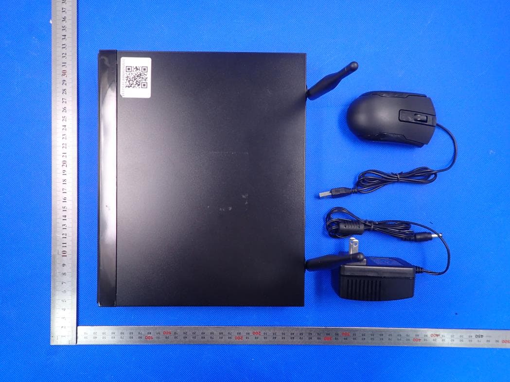
Click to zoom
Application Details
- Equipment Class
- DTS - Digital Transmission System
- Date of Grant
- Apr 30, 2020
- Application Purpose
- Original Equipment
- Date of Application
- Apr 30, 2020
- Equipment Note
- Wireless NVR
- Frequency Range
- 2412.00000000 - 2462.00000000
- Company
- Ansjer Electronics Co., Ltd
- Country
- China
Documents & Files
Document Text
Text extracted from the exhibit documents filed with the FCC. Open a document above to read the original.
Users Manual
DIY Do-It-Yourself iOSADCloudAndroid Quick Start Guide Wireless NVR System With H.264 Compression FCC Warning This device complies with Part 15 of the FCC Rules: Operation is subject to the following two conditions: 1. This device may not cause harmful interference and 2. This device must accept any interference that is received, including any interfer ence that may cause undesired operation. Manufacturer: Ansjer Electronics Co., Ltd RF exposure warning : This equipment complies with FCC radiation exposure limits set forth for an uncontrolled environment. This equipment shall be installed and operated with minimum distance 20cm between the radiator & body. This device is acting as slave and operating in the 2.4 GHz (2412 ~2462 MHz) band. Ad Hoc function is supported but not able to operate on non-US frequencies. Do not use the device with the environment which below minimum -30 or maximum over 50 . NOTE: This equipment has been tested and found to comply with the limits for a Class B digital device, pursuant to part 15 of the FCC Rules. These limits are designed to provide reasonable protection against harmful interference in a residential installation. This equipment generates uses and can radiate radio frequency energy and, if not installed and used in accordance with the instructions, may cause harmful interference to radio communications. However, there is no guarantee that interference will not occur in a particular installation. If this equipment does cause harmful interference to radio or television reception, which can be determined by turning the equipment off and on, the user is encouraged to try to correct the interference by one or more of the following measures: - Reorient or relocate the receiving antenna. - Increase the separation between the equipment and receiver. -Connect the equipment into an outlet on a circuit different from that to which the receiver is connected. -Consult the dealer or an experienced radio/TV technician for help Changes or modifications not expressly approved by the party responsible for compliance could void the user's authority to operate the equipment. 1 IMPORTANT! This instruction guides you how to install surveillance system. What accessories you need before getting started 1.One monitor or TV,can not be less than 19" 2.One VGA Cable/one HDMI Cable,use any one that monitor supports 3.One surge protector (advisable) 4.Power supplies for the NVR and cameras. Only use approved PSU's from your supplier. 5.Appropriate tools for installation. Note: This instruction guide provides basic information on how to install your CCTV system. In a few seconds, you can see the Wizard Setting. Then set password to login the system . (Password must be at least 6 characters) Connect the WiFi Camera with Power. Connect Monitor to the WiFi NVR with HDMI, or VGA Port Connect the NVR to Router with an Ethernet cable Plug the Mouse to the USB port Plug NVR to Power 3 1 2 4 5 2 5 Monitor/TV (VGA/HDMI) 4 Mouse & USB BACK UP Power Port 3 Router Camera 1 Install Your System A 2 Please download the App called ADCloud from Google Play or the App Store. The UID (User ID) is the cloud ID number, which is used to connect your DVR with the internet via your router, to remotely view your CCTV cameras via the app. For more details please read the REMOTE SURVEILLANCE GUIDE on page 6. SETTINGS WIZARD B Before turning on your NVR, ensure that all connections are correctly installed. POWER ON AND LOGIN Connect the NVR with the power supply to start-up. The light labelled POWER on the front bezel will illuminate. After the NVR start-up, a Wizard Setting panel displays to choose your required settings, including language, date format, time format, time zone, system date & system time as shown below. NB: The Wizard Settings menu will automatically display after restarting the NVR, This can be disabled by removing the tick √. First Time Login After exiting Wizard Settings,Set Password dialogue box is presented. Enter password, minimum of 6 characters and re-enter to confi rm. After the password is set, the login box is presented. Login After exiting Wizard Settings, login to the DVR. Double click the screen,(left-click on Mouse) and the Login dialogue box is presented. The default User Name is “admin” Enter password 3 STEP 1. Right click mouse for quick shortcut menu and select Main Menu STEP 2. Click Setup, then choose Basic menu STEP 3. Select the desired Video Output resolution STEP 4. Click Apply to save the settings STEP 5. Click Exit to restart system, and then Login NB: The default value is 1024 x 768 so choose the max output resolution your monitor supports, to view the best resolution MOTION C Select Camera. Tick the Camera Channel you want to record on motion detection. Holding Time. Set recording time length after motion stops. Trigger. Multiple channels can be set to record when motion is detected by one of cameras. For example, when camera 1 detects motion,camera 2 and camera 3 can be triggered to record as well. Area. It is possible to set the sensitivity area of camera viewing range. Click STAR to make the whole viewing range as sensitivity area; Click Trash Box to remove areas; Click and drag mouse to draw or erase the sensitive area. Click to save settingClick to exit As color and luminance are important for sensitivity, it is necessary to adjust its value under specifi c conditions. The default value is 4 while value range is from 1 to 8. Right click the mouse to show or hide the control menu at the bottom of the screen. Test the setting by moving something or ask someone to walk through the grid area within the camera view range. If the DVR detects movement within the grid area, a yellow fi gure would be presented in the screen. The grid should not cover fl ags, trees or other movable objects to avoid any false alerts. CHANGING DISPLAY RESOLUTION Optimize the NVR Video output to match the monitor output, using the following steps: NB: Make sure the monitor supports the…
Text truncated - open the document above for the full version.
External Photos
External Photos ALL VIEW OF EUT TOP VIEW OF EUT BOTTOM VIEW OF EUT FRONT VIEW OF EUT BACK VIEW OF EUT LEFT VIEW OF EUT WIFI Antenna 1 WIFI Antenna 2 RIGHT VIEW OF EUT
ID Label/Location Info
FCC ID Label Location FCC ID: 2ANTCZR08DP This device complies with Part 15 of the FCC Rules. Operation is subject to the following two conditions: (1) this device may not cause harmful interference, and (2) this device must accept any interference received, including interference that may cause undesired operation.
Internal Photos
Internal Photos OPEN VIEW OF EUT-1 OPEN VIEW OF EUT-2 INTERNAL VIEW-1 OF EUT INTERNAL VIEW-2 OF EUT INTERNAL VIEW-3 OF EUT INTERNAL VIEW-4 OF EUT INTERNAL VIEW-5 OF EUT INTERNAL VIEW-6 OF EUT INTERNAL VIEW-7 OF EUT INTERNAL VIEW-8 OF EUT INTERNAL VIEW-9 OF EUT INTERNAL VIEW-10 OF EUT INTERNAL VIEW-11 OF EUT INTERNAL VIEW-12 OF EUT INTERNAL VIEW-13 OF EUT
Operational Description
Declaration concerning Antenna Specification It is hereby declared that the product Model No.: ZR08DP, PQ08W, SQ08W, NQ08W, RQ08W, PQ04W, SQ04W, NQ04W, RQ04W, ZR08DS, ZR08DN, ZR08DR, ZR08DL, 89000T, 89001T, 89023T, 89025T, 99000T, 99001T, 99023T, 99025T FCC ID: 2ANTCZR08DP fulfills the requirement in FCC test relating to the antenna type. The device specified above confirms to the FCC recommendations for external antenna type(s) described below: 1 Type of antenna: Dedicated Antenna Gain of the antenna: 5dBi Frequency range: 2.412 GHz~2.462GHz 2 Type of antenna: Dedicated Antenna Gain of the antenna: 5dBi Frequency range: 2.412 GHz~2.462GHz The mounting of the antenna is fixed to the radio module and no other antenna should be used. Company name: Ansjer Electronics Co., Ltd Address: 301# , 1st Building,No.21 Yongtian Road, Xiangzhou 519000, Zhuhai, Guangdong, China Place: Zhuhai Date: 2020-04-13 Signature:
RF Exposure Info
RF EXPOSURE EVALUATION 1. PRODUCT INFORMATION Product Description Wireless NVR Model Name ZR08DP, PQ08W, SQ08W, NQ08W, RQ08W, PQ04W, SQ04W, NQ04W, RQ04W, ZR08DS, ZR08DN, ZR08DR, ZR08DL, 89000T, 89001T, 89023T, 89025T, 99000T, 99001T, 99023T, 99025T FCC ID 2ANTCZR08DP 2. EVALUATION METHOD AND LIMIT Human exposure to RF emissions from mobile devices (47 CFR §2.1091) may be evaluated based on the MPE limits adopted by the FCC for electric and magnetic field strength and/or power density, as appropriate, since exposures are assumed to occur at distances of 20 cm or more from persons. LIMITS FOR GENERAL POPULATION / UNCONTROLLED EXPOSURE Frequency Range (MHz) E-field Strength (E) (V/m) Magnetic Field Strength (H) (A/m) Power Density (S) (mW/cm 2 ) Averaging Time |E| 2 , |H| 2 or S (Minutes) 0.3 -- 1.34 614 1.63 (100)* 30 1.34 -- 30 824/f 2.19/f (180/f 2 )* 30 30 -- 300 27.5 0.073 0.2 30 300 -- 1500 -- -- f/1500 30 1500 -- 100,000 -- -- 1.0 30 *Note: 1. f= Frequency in MHz * Plane-wave Equivalent Power Density 2. The averaging time for General Population/Uncontrolled exposure to fixed transmitters is not applicable for mobile and portable transmitters. See 47 CFR §§2.1091 and 2.1093 on source-based time-averaging requirement for mobile and portable transmitters. S=PG/4πR² Where: S=power density P=power input to antenna G=power gain of the antenna in the direction of interest relative to an isotropic radiator R=distance to the center of radiation of the antenna 3. CALCULATION A minimum test separation distance ≥ 20 cm is required between the antenna and radiating structures of the device and nearby persons to apply mobile device exposure limits. The distance must be at least 20 cm and fully supported by the operating and installation configurations of the transmitter and its antenna(s), according to the source-based time-averaged maximum power requirements of § 2.1091(d)(2). In cases where cable losses or other attenuations are applied to determine compliance, the most conservative operating configurations and exposure conditions must be evaluated. WIFI PART Antenna Gain=5dBi (Numeric 3.16), π=3.14 802.11b Single mode(Worst case) 802.11n MIMO mode(Worst case) Note: Only the worst case recorded. Frequency Output Power Output Power Power Density Power Density Limit MHz dBm mW mW/cm 2 mW/cm 2 2412 13.70 23.44 0.015 1 Frequency Output Power Output Power Power Density Power Density Limit MHz dBm mW mW/cm 2 mW/cm 2 2422 14.95 31.26 0.020 1
Test Report
Page 1 of 98 Report No.: AGC06662200201FE05 FCC ID : 2ANTCZR08DP APPLICATION PURPOSE : Original Equipment PRODUCT DESIGNATION : Wireless NVR BRAND NAME : N/A MODEL NAME : ZR08DP, PQ08W, SQ08W, NQ08W, RQ08W, PQ04W, SQ04W, NQ04W, RQ04W, ZR08DS, ZR08DN, ZR08DR, ZR08DL, 89000T, 89001T, 89023T, 89025T, 99000T, 99001T, 99023T, 99025T APPLICANT : Ansjer Electronics Co., Ltd DATE OF ISSUE : Apr. 10, 2020 STANDARD(S) TEST PROCEDURE(S) : FCC Part 15.247 REPORT VERSION : V1.0 Attestation of Global Compliance (Shenzhen) Co., Ltd CAUTION: This report shall not be reproduced except in full without the written permission of the test laboratory and shall not be quoted out of context. FCC Test Report Report No.: AGC06662200201FE05 Page 2 of 98 REPORT REVISE RECORD Report Version Revise Time Issued Date Valid Version Notes V1.0 / Apr. 10, 2020 Valid Initial Release Report No.: AGC06662200201FE05 Page 3 of 98 TABLE OF CONTENTS 1. VERIFICATION OF CONFORMITY ............................................................................................................... 5 2. GENERAL INFORMATION ............................................................................................................................ 6 2.1. PRODUCT DESCRIPTION ..................................................................................................................... 6 2.2. TABLE OF CARRIER FREQUENCYS ..................................................................................................... 6 2.3. IEEE 802.11N MODULATION SCHEME .................................................................................................. 7 2.4. RELATED SUBMITTAL(S) / GRANT (S) .................................................................................................. 7 2.5. TEST METHODOLOGY .......................................................................................................................... 7 2.6. SPECIAL ACCESSORIES ....................................................................................................................... 7 2.7. EQUIPMENT MODIFICATIONS .............................................................................................................. 7 3. MEASUREMENT UNCERTAINTY ................................................................................................................. 8 4. DESCRIPTION OF TEST MODES ................................................................................................................. 9 5. SYSTEM TEST CONFIGURATION ............................................................................................................. 10 5.1. CONFIGURATION OF EUT SYSTEM ................................................................................................... 10 5.2. EQUIPMENT USED IN EUT SYSTEM ................................................................................................... 10 5.3. SUMMARY OF TEST RESULTS ............................................................................................................ 10 6. TEST FACILITY ........................................................................................................................................... 11 7. OUTPUT POWER ........................................................................................................................................ 12 7.1. MEASUREMENT PROCEDURE ........................................................................................................... 12 7.2. TEST SET-UP (BLOCK DIAGRAM OF CONFIGURATION) ................................................................... 12 7.3. LIMITS AND MEASUREMENT RESULT ............................................................................................... 13 8. 6 DB BANDWIDTH ...................................................................................................................................... 15 8.1. MEASUREMENT PROCEDURE ........................................................................................................... 15 8.2. TEST SET-UP (BLOCK DIAGRAM OF CONFIGURATION) ................................................................... 15 8.3. LIMITS AND MEASUREMENT RESULTS ............................................................................................. 16 9. CONDUCTED SPURIOUS EMISSION ........................................................................................................ 24 9.1. MEASUREMENT PROCEDURE ........................................................................................................... 24 9.2. TEST SET-UP (BLOCK DIAGRAM OF CONFIGURATION) ................................................................... 24 9.3. MEASUREMENT EQUIPMENT USED .................................................................................................. 24 9.4. LIMITS AND MEASUREMENT RESULT ............................................................................................... 24 10. MAXIMUM CONDUCTED OUTPUT POWER SPECTRAL DENSITY ....................................................... 43 Report No.: AGC06662200201FE05 Page 4 of 98 10.1 MEASUREMENT PROCEDURE .......................................................................................................... 43 10.2 TEST SET-UP (BLOCK DIAGRAM OF CONFIGURATION) .................................................................. 43 10.3 MEASUREMENT EQUIPMENT USED ................................................................................................. 43 10.4 LIMITS AND MEASUREMENT RESULT .............................................................................................. 43 11. RADIATED EMISSION ............................................................................................................................... 57 11.1. MEASUREMENT PROCEDURE ......................................................................................................... 57 11.2. TEST SETUP ......................................…
Text truncated - open the document above for the full version.
Test Report
Report No.: AGC06662200201FE05 Page 62 of 98 RADIATED EMISSION ABOVE 1GHZ EUT Wireless NVR Model Name ZR08DP Temperature 25°C Relative Humidity 55.4% Pressure 960hPa Test Voltage Normal Voltage Test Mode 802.11b with date rate 1 2412MHZ Antenna Horizontal Frequency Meter Reading Factor Emission Level Limits Margin Value Type (MHz) (dBμV) (dB) (dBμV/m) (dBμV/m) (dB) 4824.044 45.36 3.72 49.08 74.00 -24.92 peak 4824.044 42.12 3.72 45.84 54.00 -8.16 AVG 7236.066 37.87 8.15 46.02 74.00 -27.98 peak 7236.066 34.18 8.15 42.33 54.00 -11.67 AVG Remark: Factor = Antenna Factor + Cable Loss – Pre-amplifier. EUT Wireless NVR Model Name ZR08DP Temperature 25°C Relative Humidity 55.4% Pressure 960hPa Test Voltage Normal Voltage Test Mode 802.11b with date rate 1 2412MHZ Antenna Vertical Frequency Meter Reading Factor Emission Level Limits Margin Value Type (MHz) (dBμV) (dB) (dBμV/m) (dBμV/m) (dB) 4824.044 47.14 3.72 51.86 74 -23.14 peak 4824.044 44.66 3.72 48.38 54 -5.62 AVG 7236.066 38.08 8.15 46.23 74 -27.77 peak 7236.066 33.42 8.15 41.57 54 -12.43 AVG Remark: Factor = Antenna Factor + Cable Loss – Pre-amplifier. Report No.: AGC06662200201FE05 Page 63 of 98 EUT Wireless NVR Model Name ZR08DP Temperature 25°C Relative Humidity 55.4% Pressure 960hPa Test Voltage Normal Voltage Test Mode 802.11b with date rate 1 2437MHZ Antenna Horizontal Frequency Meter Reading Factor Emission Level Limits Margin Value Type (MHz) (dBμV) (dB) (dBμV/m) (dBμV/m) (dB) 4874.044 46.63 3.75 50.38 74 -23.62 peak 4874.044 42.84 3.75 46.59 54 -7.71 AVG 7311.066 39.29 8.16 47.45 74 -26.55 peak 7311.066 37.18 8.16 45.34 54 -8.66 AVG Remark: Factor = Antenna Factor + Cable Loss – Pre-amplifier. EUT Wireless NVR Model Name ZR08DP Temperature 25°C Relative Humidity 55.4% Pressure 960hPa Test Voltage Normal Voltage Test Mode 802.11b with date rate 1 2437MHZ Antenna Vertical Frequency Meter Reading Factor Emission Level Limits Margin Value Type (MHz) (dBμV) (dB) (dBμV/m) (dBμV/m) (dB) 4874.044 47.15 3.75 50.90 74 -23.10 peak 4874.044 45.22 3.75 48.97 54 -5.03 AVG 7311.066 42.71 8.16 50.87 74 -23.13 peak 7311.066 39.52 8.16 47.68 54 -6.32 AVG Remark: Factor = Antenna Factor + Cable Loss – Pre-amplifier. Report No.: AGC06662200201FE05 Page 64 of 98 EUT Wireless NVR Model Name ZR08DP Temperature 25°C Relative Humidity 55.4% Pressure 960hPa Test Voltage Normal Voltage Test Mode 802.11b with date rate 1 2462MHZ Antenna Horizontal Frequency Meter Reading Factor Emission Level Limits Margin Value Type (MHz) (dBμV) (dB) (dBμV/m) (dBμV/m) (dB) 4924.044 47.89 3.81 51.70 74 -22.30 peak 4924.044 44.20 3.81 48.01 54 -5.99 AVG 7386.066 40.53 8.19 48.72 74 -25.28 peak 7386.066 38.90 8.19 47.09 54 -6.91 AVG Remark: Factor = Antenna Factor + Cable Loss – Pre-amplifier. EUT Wireless NVR Model Name ZR08DP Temperature 25°C Relative Humidity 55.4% Pressure 960hPa Test Voltage Normal Voltage Test Mode 802.11b with date rate 1 2462MHZ Antenna Vertical Frequency Meter Reading Factor Emission Level Limits Margin Value Type (MHz) (dBμV) (dB) (dBμV/m) (dBμV/m) (dB) 4924.044 48.14 3.81 51.95 74 -22.05 peak 4924.044 44.37 3.81 48.18 54 -5.82 AVG 7386.066 39.88 8.19 48.07 74 -25.93 peak 7386.066 35.35 8.19 43.54 54 -10.46 AVG Remark: Factor = Antenna Factor + Cable Loss – Pre-amplifier. RESULT: PASS Note: Other emissions from 1G to 25 GHz are considered as ambient noise. No recording in the test report. Factor = Antenna Factor + Cable loss - Amplifier gain, Over=Measure-Limit. The “Factor” value can be calculated automatically by software of measurement system. All test modes had been pre-tested. The 802.11b mode is the worst case and recorded in the report. Report No.: AGC06662200201FE05 Page 65 of 98 12. BAND EDGE EMISSION 12.1. MEASUREMENT PROCEDURE Radiated restricted band edge measurements The radiated restricted band edge measurements are measured with an EMI test receiver connected to the receive antenna while the EUT is transmitting 12.2. TEST SET-UP same as 11.2 Note: 1. Factor=Antenna Factor + Cable loss - Amplifier gain. Field Strength=Factor + Reading level 2. The factor had been edited in the “Input Correction” of the Spectrum Analyzer. So the Amplitude of test plots is equal to Reading level plus the Factor in dB. Use the A dB(μV) to represent the Amplitude. Use the F dB(μV/m) to represent the Field Strength. So A=F. Report No.: AGC06662200201FE05 Page 66 of 98 12.3. TEST RESULT EUT Wireless NVR Model Name ZR08DP Temperature 25°C Relative Humidity 55.4% Pressure 960hPa Test Voltage Normal Voltage Test Mode 802.11b with data rate 1 2412MHZ Antenna Horizontal PK AV RESULT: PASS Report No.: AGC06662200201FE05 Page 67 of 98 EUT Wireless NVR Model Name ZR08DP Temperature 25°C Relative Humidity 55.4% Pressure 960hPa Test Voltage Normal Voltage Test Mode 802.11b with data rate 1 2412MHZ Antenna Vertical PK AV RESULT: PASS Report No.: AGC06662200201FE05 Page 68 of 98 EUT Wireless NVR Model Name ZR08DP Temperature 25°C Relative Humidity 55.4% Pressure 960hPa Test Voltage Normal Voltage Test Mode 802.11b with data rate 1 2462MHZ Antenna Horizontal PK AV RESULT: PASS Report No.: AGC06662200201FE05 Page 69 of 98 EUT Wireless NVR Model Name ZR08DP Temperature 25°C Relative Humidity 55.4% Pressure 960hPa Test Voltage Normal Voltage Test Mode 802.11b with data rate 1 2462MHZ Antenna Vertical PK AV RESULT: PASS Report No.: AGC06662200201FE05 Page 70 of 98 EUT Wireless NVR Model Name ZR08DP Temperature 25°C Relative Humidity 55.4% Pressure 960hPa Test Voltage Normal Voltage Test Mode 802.11g with data rate 6 2412MHZ Antenna Horizontal PK AV RESULT: PASS Report No.: AGC06662200201FE05 Page 71 of 98 EUT Wireless NVR Model Name ZR08DP Temperature 25°C Relative Humidity 55.4% Pressure 960hPa Test Voltage Normal Voltage Test Mode 802.11g with data rate 6 2412MHZ Antenna Vertical PK AV RESULT: PASS Report No.: AGC06662200201FE05 Page 72 of 98 EUT Wireless NVR Model Name ZR08DP Temperature 25°C Relative Humidity 55.4% Pressure 960hPa Test Voltage Normal Voltage Test Mode 802…
Text truncated - open the document above for the full version.
Test Setup Photos
Test Setup Photos FCC RADIATED EMISSION TEST SETUP BELOW 1GHZ FCC RADIATED EMISSION TEST SETUP ABOVE 1GHZ FCC LINE CONDUCTED EMISSION TEST SETUP
Contact Information
Applicant
Lanner Lan
Test Firm
Attestation of Global Compliance (Shenzhen) Co., LDoris Li
[email protected]+86-755-25234088
Technical Specifications
| # | Rule Parts | Frequency Range | Power Output |
|---|---|---|---|
| 1 | 15C | 2.41 GHz - 2.46 GHz | 31.30 mW |
Other Applications from Ansjer Electronics Co., Ltd

2ANTC-C520M
Feb 13, 2026Wireless IP Camera
Equipment Class
DTS - Digital Transmission System
2ANTC-ZR08WS
Jan 26, 2026Wireless NVR
Equipment Class
DTS - Digital Transmission System
2ANTC-C528M
Sep 08, 2024Wireless IP Camera
Equipment Class
NII - Unlicensed National Information Infrastructure TX
2ANTC-C291
Sep 04, 2024Wireless IP Camera
Equipment Class
DTS - Digital Transmission System
2ANTC-C688
Aug 23, 2024Wireless IP Camera
Equipment Class
DTS - Digital Transmission System