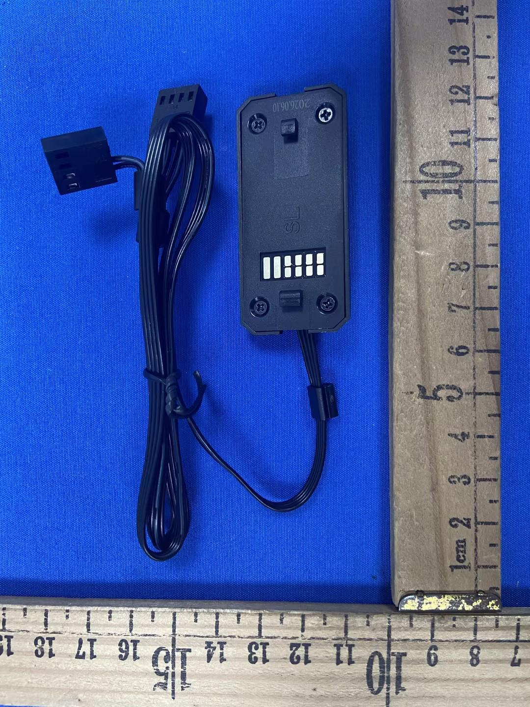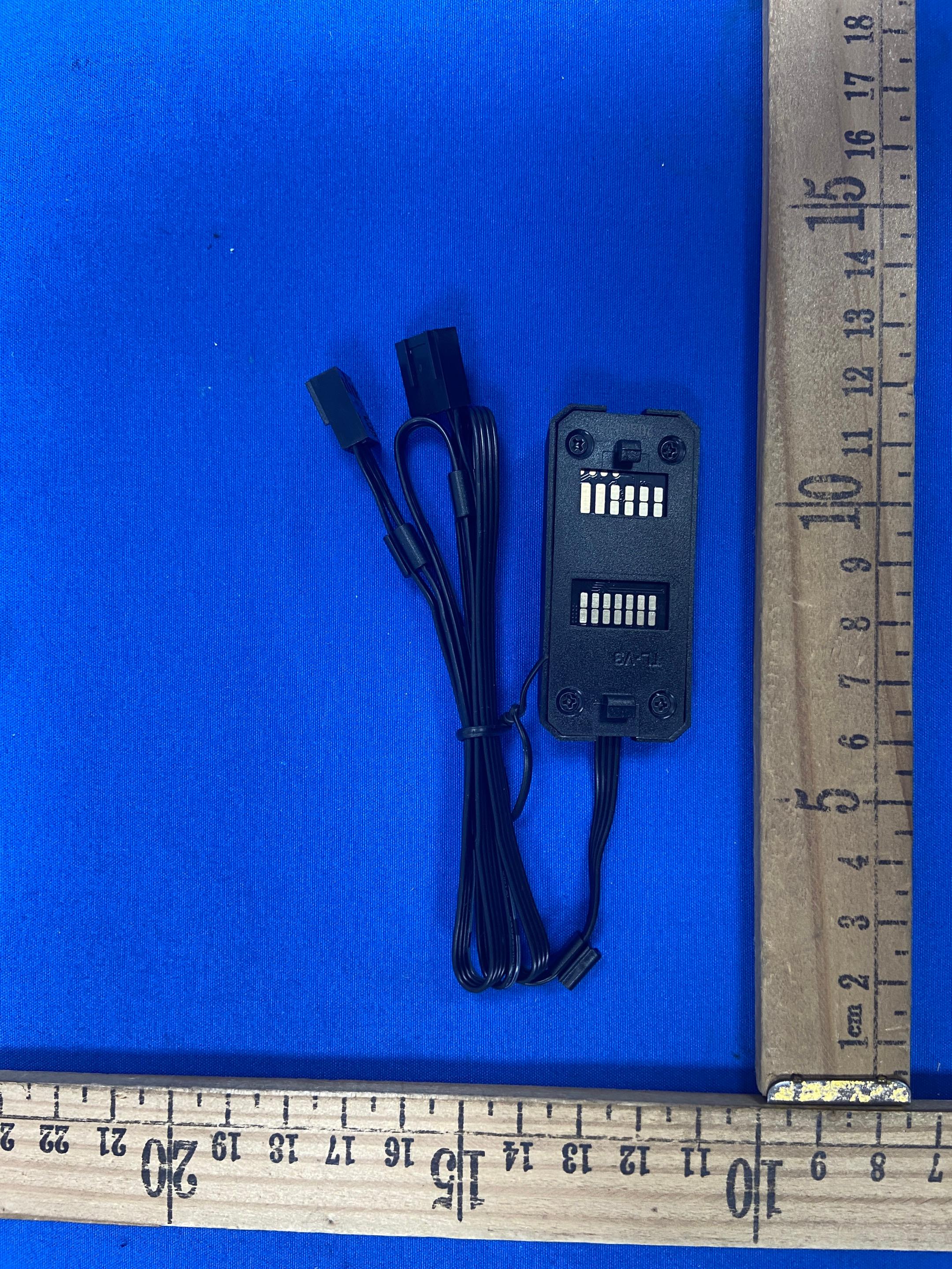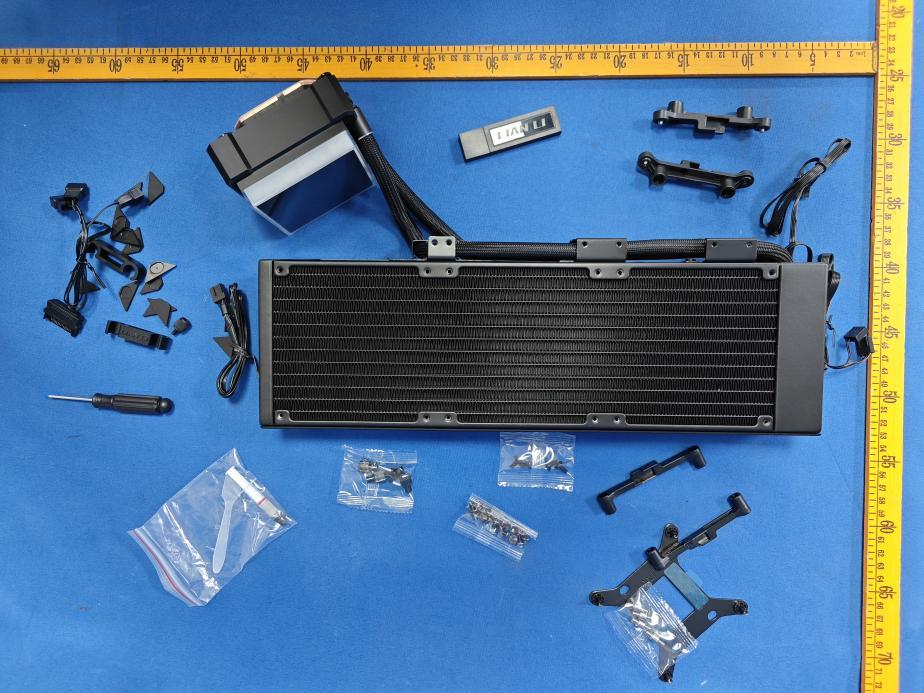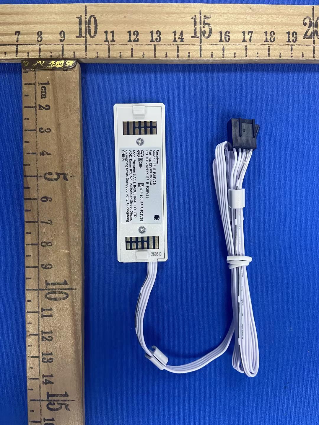
Text extracted from the exhibit documents filed with the FCC. Open a document above to read the original.
UNI FAN P28 V2 Installation Guide ▪Guide d'installation▪Installationsanleitung▪Guía de instalación ▪Installationsguide ▪Instrukcja instalacji▪Руководствопоустановке ▪安裝指南▪インストールガイド Package Contents - 1 -- 2 -- 3 -- 4 - ▪Contenu du colis▪Verpackungsinhalt▪Contenido del paquete▪Förpackningens innehåll ▪Zawartość opakowania ▪Содержимоеупаковки▪包裝內容物▪パッケージ内容物 Fan to Fan Connection ▪Connexion ventilateur à ventilateur ▪Lüfter-zu-Lüfter-Verbindung▪Conexión de ventilador a ventilador ▪Fläkt till fläkt-anslutning ▪Połączenie wentylatora z wentylatorem▪Соединениевентиляторовмеждусобой ▪風扇之間的連接▪ファン同士の接続 Receiver installation ▪Installation du récepteur▪Empfängerinstallation▪Instalación del receptor▪Installation av mottagare ▪Instalacja odbiornika▪Установкаприемника▪接收器安裝▪レシーバーの取り付け Max 4 LED fans per channel ▪Omnidirectional, both sides can be used ▪Sans orientation, les deux côtés peuvent être utilisés ▪Richtungsunabhängig, beide Seiten können verwendet werden ▪Sin orientación, ambos lados se pueden utilizar ▪Riktningoberoende, båda sidorna kan användas ▪Bez kierunku, obie strony mogą być używane ▪Безнаправленности,обестороны можноиспользовать ▪無方向性,兩側皆可使用 ▪方向性なし 両面使用可能 ▪Fan Light Switch ▪Interrupteur d'éclairage du ventilateur ▪Lüfterbeleuchtungsschalter ▪Interruptor de iluminación del ventilador ▪Fläktbelysningsbrytare ▪Przełącznik oświetlenia wentylatora ▪Переключательподсветкивентилятора ▪風扇燈光切換 ▪ファンライト切替スイッチ ▪Fan Speed Levels ▪Niveaux de vitesse du ventilateur ▪Lüftergeschwindigkeitsstufen ▪Niveles de velocidad del ventilador ▪Fläkthastighetsnivåer ▪Poziomy prędkości wentylatora ▪Уровнискоростивентилятора ▪風扇轉速等級 ▪ファン速度レベル Usage of the Rubber Pads ▪Utilisation des patins en caoutchouc ▪Verwendung der Gummipads ▪Uso de las almohadillas de goma ▪Användning av gummidynor ▪Zastosowanie podkładek gumowych▪Использованиерезиновыхпрокладок ▪橡膠墊使用方式▪ゴムパッドの使用方法 ▪Install screws and replace rubber pads for a clean look ▪Visser et remplacer les patins pour un rendu propre ▪Schrauben einsetzen, Gummipads ersetzen ▪Instalar tornillos y cambiar almohadillas ▪Skruva fast och byt gummipads ▪Zamontuj śruby i wymień podkładki ▪Установитьвинтыизаменитьпрокладки ▪安裝螺絲並更換橡膠墊,外觀更整潔 ▪ネジ固定・ゴムパッド交換で見た目を整える ▪Remove fan clip if radiator ports interfere ▪Retirer le clip si les ports du radiateur gênent ▪Clip entfernen bei Störung durch Radiatoranschlüsse ▪Retire el clip si los puertos del radiador interfieren ▪Ta bort klämman om radiatorportar stör ▪Usuń klips, jeśli porty chłodnicy przeszkadzają ▪Снимитеклипсу,еслипорты радиаторамешают ▪若水冷排進出水干涉,移除卡扣鎖 ▪干渉時はクリップを取り外す Remove the Fan Interlocking Key ▪Retirez la clé d’interconnexion du ventilateur ▪Entfernen Sie den Lüfterverriegelungsschlüssel ▪Retire la llave de interconexión del ventilador▪Ta bort fläktens sammankopplingsnyckel ▪Usuń klucz blokujący wentylator▪Снятиефиксаторавентилятора▪風扇扣鎖拆除▪ファン連結キーを取り外します FLEX LED Receiver Model: RF-R-P28V2 Rating: 12V 100mA 無線產品配對操作說明 https://lian-li.com/zh-TW/l-connect3/l-connect3-manual-l-wireless-sync/ x 4 FCC Caution. This device complies with part 15 of the FCC Rules. Operation is subject to the following two conditions: (1) This device may not cause harmful interference, and (2) this device must accept any interference received, including interference that may cause undesired operation. Any Changes or modifications not expressly approved by the party responsible for compliance could void the user's authority to operate the equipment. Note: This equipment has been tested and found to comply with the limits for a Class B digital device, pursuant to part 15 of the FCC Rules. These limits are designed to provide reasonable protection against harmful interference in a residential installation. This equipment generates uses and can radiate radio frequency energy and, if not installed and used in accordance with the instructions, may cause harmful interference to radio communications. However, there is no guarantee that interference will not occur in a particular installation. If this equipment does cause harmful interference to radio or television reception, which can be determined by turning the equipment off and on, the user is encouraged to try to correct the interference by one or more of the following measures: -Reorient or relocate the receiving antenna. -Increase the separation between the equipment and receiver. -Connect the equipment into an outlet on a circuit different from that to which the receiver is connected. -Consult the dealer or an experienced radio/TV technician for help. *RF warning for Portable device: The device has been evaluated to meet general RF exposure requirement. The device can be used in portable exposure condition without restriction. 2.4g wireless spec : frequency 2402-2480MHz Transmition : Below 10mw LIAN LI INDUSTRIAL CO., LTD. 2F., NO. 20, ANKANG RD., NEIHU DIST., TAIPEI CITY 114, TAIWAN [email protected] ▪3-Year Warranty ▪ Garantie de 3 an ▪ 3 Jahr Garantie ▪ 3 año de garantía ▪ 3 års garanti ▪ 3 rok gwarancji ▪Гарантия3год ▪ 3 年保固 ▪3 年間保証 低功率射頻器材技術規範 取得審驗證明之低功率射頻器材,非經核准,公司、商號或使用者均不得擅自變更頻率、加大功率或變更原設計之特性及 功能。低功率射頻器材之使用不得影響飛航安全及干擾合法通信;經發現有干擾現象時,應立即停用,並改善至無干擾時 方得繼續使用。前述合法通信,指依電信管理法規定作業之無線電通信。低功率射頻器材須忍受合法通信或工業、科學及 醫療用電波輻射性電機設備之干擾。 G50.12P28V2B(W).00 - 5 -- 6 -- 7 -- 8 - 1 2 ▪Use wireless for fan and RGB control via L-Connect 3. ▪Utilisez le sans fil pour contrôler ventilateur et RGB via L-Connect 3. ▪Wireless für Lüfter- und RGB-Steuerung über L-Connect 3. ▪Use inalámbrico para control de ventilador y RGB mediante L-Connect 3. ▪Använd wireless för fläkt- och RGB-styrning via L-Connect 3. ▪Wireless do sterowania wentylatorami i RGB przez L-Connect 3. ▪ИспользуйтеwirelessдляуправлениявентиляторамииRGBчерезL-Connect3. ▪使用無線透過L-Connect3控制風扇與RGB。 ▪wirelessでL-Connect3によるファン・RGB制御。 f ▪Each L-Wireless Controller supports 10 device channels. ▪Chaque L-Wireless Controller prend en charg…
Text truncated - open the document above for the full version.
LIANLIINDUSTRIALCO.,LTD. CoveredEquipmentCertificationAttestationLetter 8/3/2026 NemkoNorthAmerica,Inc. 303RiverRoad Ottawa K1V1H2 Canada ATTN.:ReviewingEngineer FCCID:2ANYX-RF-R-P28V2 LIANLIINDUSTRIALCO.,LTD.(“theapplicant”)certifiesthattheequipmentforwhich authorizationissoughtisnot“covered”equipmentprohibitedfromreceivingan equipmentauthorizationpursuanttosection2.903oftheFCCrules. Note:Iftheequipmentforwhichtheapplicantseeksauthorizationisproducedby anyoftheentitiesidentifiedonthecurrentCoveredList,theapplicantshould includeanexplanationonwhytheequipmentisnot“covered”equipment. LIANLIINDUSTRIALCO.,LTD.(“theapplicant”)certifiesthat,asofthedateofthefiling oftheapplication,theapplicantisnotidentifiedontheCoveredListasanentity producing“covered”equipment. LIANLIINDUSTRIALCO.,LTD.(“theapplicant”)certifiesthattheequipmentforwhich authorizationissoughtdoesnotincludecybersecurityoranti-virussoftwareproducedor providedbyKasperskyLab,Inc.oranyofitssuccessorsandassignees,including equipmentwithintegratedKasperskyLab,Inc.(oranyofitssuccessorsandassignees) cybersecurityoranti-virussoftwarepursuanttoDA-24-886andKDB986446D01 CoveredEquipmentGuidancesectionB(2a). Signed: Printedname:JOVIWEI Title:Manager CompanyName:LIANLIINDUSTRIALCO.,LTD. Date:8/3/2026
LIANLIINDUSTRIALCO.,LTD. 8/3/2026 NemkoNorthAmerica,Inc. 303RiverRoad Ottawa,Ontario,Canada K1V1H2 REQUESTFORCONFIDENTIALITY-FCC FCCID:2ANYX-RF-R-P28V2 PursuanttoSections0.457(d)(1)(ii)and0.459oftheCommission’sRulesandFCCGuidance document726920,weherebyrequestconfidentialtreatmentofinformationaccompanyingthis applicationasoutlinedbelow: PERMANENTLONG-TERMCONFIDENTIALITY: Schematics BlockDiagrams TheoryofOperation Theaboveinformationcontainstradesecretsandproprietaryinformationnotcustomarilyreleasedto thepublic.Thepublicdisclosureofthisinformationmightbeharmfultotheapplicantandprovide unjustifiedbenefitstoitscompetitors.TheApplicantunderstandsthatpursuanttoRule 0.457(d)(1)(ii),disclosureofthisApplicationandallaccompanyingmaterialswillnotbemadebefore thedateoftheGrantforthisApplication. Sincerely, Signed: Printedname:JOVIWEI Title:Manager
FCCID:2ANYX-RF-R-P28V2 FCCID:2ANYX-RF-R-P28V2 FCCID:2ANYX-RF-R-P28V2 FCCID:2ANYX-RF-R-P28V2 FCCID:2ANYX-RF-R-P28V2 FCCID:2ANYX-RF-R-P28V2 FCCID:2ANYX-RF-R-P28V2
LabelandLabelLocation
FCCID:2ANYX-RF-R-P28V2 FCCID:2ANYX-RF-R-P28V2
Page 1 of 3 RF EXPOSURE EVALUATION FCC ID: 2ANYX-RF-R-P28V2 Product Name : P28 V2 Receiver Model Name : RF-R-P28V2 Operating frequency : 2402-2480MHz Numbers of Channel : 40 channels for 2.4G SRD Antenna Type : PCB antenna Antenna Gain : 2.1dBi Type of Modulation : GFSK Power supply : DC12V(USB HUB DC5V) Hardware Version : V1.0 Software Version : V1.9 Page 2 of 3 Standard Requirement According to § 15.249 and § 1.1307b(1), systems operating under the provisions of this section shall be operated in a manner that ensures that the public is not exposed to radio frequency energy levels in excess of the Commission’s guidelines. See KDB 447498 D01 General RF Exposure Guidance v06, section 4. 3. 1. The 1-g and 10-g SAR test exclusion thresholds for 100MHz to 6GHz at test separation distances ≤ 50mm are determined by: [ (max. power of channel, including tune-up tolerance, mW)/(min. test separation distance, mm)]*[ √f(GHz)] ≤3.0 for 1-g SAR and ≤7.5 for 10-g SAR extremity SAR, where ⚫ f(GHz) is the RF channel transmit frequency in GHz ⚫ Power and distance are rounded to the nearest mW and mm before calculation ⚫ The result is rounded to one decimal place for comparison. The test exclusions are applicable only when the minimum test separation distance is ≤ 50mm and for transmission frequencies between 100MHz and 6GHz. When the minimum test separation distance is <5mm, a distance of 5mm is applied to determine SAR test exclusion. Routine SAR evaluation refers to that specifically required by § 2.1093, using measurements or computer simulation. When routine SAR evaluation is not required, portable transmitters with output power greater than the applicable low threshold require SAR evaluation to quality for TCB approval. RF Output power Freq. (MHz) Field strength(max)(dBuV/m) EIRP (max) (dBm) 2440 94.76 -0.44 Note: EIRP=E-104.8+20logD, Where E is the electric field strength in dBμV/m. EIRP is the equivalent isotropically radiated power in dBm. d is the specified measurement distance in m. where D=3, EIRP=E-95.2. Page 3 of 3 Channel (MHz) Maximum output power (dBm) Tune up tolerance (dBm) Max Tune Up Power (mW) Distance(mm) Calculation results Limit Operating Mode 2440 -0.44 -0.44±1 1.137627 5 0.355406 3 GFSK_1Mbps According to KDB 447498, The device only support 2.4G SRD function, and no simultaneous SAR measurement is required. Signature Simon Pu Manager Date: 2026-07-31
Page 1 of 41 FCC TEST REPORT FCC ID: 2ANYX-RF-R-P28V2 Product : P28 V2 Receiver Model Name : RF-R-P28V2 Brand : LIAN LI Report No. : PTC26052119403E-FC01 Prepared for LIAN LI INDUSTRIAL CO.,LTD. 11-1, KONG-CHIEN N.RD; LIU-TU INDUSTRIAL PARK Keelung Taiwan Prepared by Precise Testing & Certification Co., Ltd. Building 1, No. 6, Tongxin Road, Dongcheng Street, Dongguan, Guangdong, China Report No.: PTC26052119403E-FC01 Page 2 of 41 1 TEST RESULT CERTIFICATION Applicant’s name : LIAN LI INDUSTRIAL CO.,LTD. Address : 11-1, KONG-CHIEN N.RD; LIU-TU INDUSTRIAL PARK Keelung Taiwan Manufacture's name : LIAN LI INDUSTRIAL CO.,LTD. Address : 11-1, KONG-CHIEN N.RD; LIU-TU INDUSTRIAL PARK Keelung Taiwan Product name : P28 V2 Receiver Model name : RF-R-P28V2 Standards : FCC Part15 Subpart C, Paragraph 15.249 Test procedure : ANSI C63.10-2020 Test Date : Jun. 08, 2026 to Jul. 08, 2026 Date of Issue : Jul. 31, 2026 Test Result : Pass This device described above has been tested by PTC, and the test results show that the equipment under test (EUT) is in compliance with the FCC requirements. And it is applicable only to the tested sample identified in the report. This report shall not be reproduced except in full, without the written approval of PTC, this document may be altered or revised by PTC, personal only, and shall be noted in the revision of the document. Test Engineer: Jack zhou / Engineer Technical Manager: Simon Pu / Manager Report No.: PTC26052119403E-FC01 Page 3 of 41 Contents Page 1 TEST RESULT CERTIFICATION.......................................................................................................................................... 2 2 TEST SUMMARY ..................................................................................................................................................................... 5 2.1 TEST SITE ....................................................................................................................................................................... 6 3 GENERAL INFORMATION .................................................................................................................................................... 7 3.1 GENERAL DESCRIPTION OF E.U.T. ............................................................................................................................... 7 3.2 CHANNEL LIST ................................................................................................................................................................ 8 4 EQUIPMENT DURING TEST ................................................................................................................................................. 9 4.1 EQUIPMENTS LIST .......................................................................................................................................................... 9 4.2 MEASUREMENT UNCERTAINTY .................................................................................................................................... 11 4.3 DESCRIPTION OF SUPPORT UNITS .............................................................................................................................. 11 5 CONDUCTED EMISSION..................................................................................................................................................... 12 5.1 E.U.T. OPERATION ...................................................................................................................................................... 12 5.2 EUT SETUP .................................................................................................................................................................. 12 5.3 TEST SET-UP (BLOCK DIAGRAM OF CONFIGURATION) ............................................................................................. 13 5.4 MEASUREMENT PROCEDURE ....................................................................................................................................... 13 5.5 CONDUCTED EMISSION LIMIT ...................................................................................................................................... 13 5.6 MEASUREMENT DESCRIPTION ..................................................................................................................................... 13 5.7 CONDUCTED EMISSION TEST RESULT ........................................................................................................................ 13 6 RADIATED EMISSION AND BAND EDGE ....................................................................................................................... 14 6.1 TEST STANDARD AND LIMIT ......................................................................................................................................... 14 6.2 TEST SETUP ................................................................................................................................................................. 15 6.3 TEST PROCEDURE ....................................................................................................................................................... 16 6.4 TEST DATA ................................................................................................................................................................... 17 7 20DB BANDWIDTH TEST ................................................................................................................................................... 28 7.1 TEST STANDARD AND LIMIT ......................................................................................................................................... 28 7.2 TEST SETUP ................................................................................................................................................................. 28 7.3 TEST PROCEDURE .......................................…
Text truncated - open the document above for the full version.
PCB Antenna for BLE Chips of WCH 2、Fea 1、Dimension of Antenna tures 3、S parameter Working bandwidth: 157MHz S11:[email protected] Dimension: 5.6*12.3mm Terminal impedance: 50ohm Max Gain: 2.1dBi RF Frequency: 2.4GHz GHz Manufacturer name: Nanjing Qinheng Microelectronics Co., Ltd. Address: No. 18, Nanjing Ningshuang Road, Qinheng Science and Technology Park Brand Name: Nanjing Qinheng Microelectronics Co., Ltd. Model Name: ANT-F-1-2.4G-1.0mmFR4-WCH 4、Gain and Radiation pattern Max gain @2.4GHz: 2.08dBi E plane: H plane: Max Gain @2.44GHz: 2.1dBi E plane: H plane: Max Gain @2.48GHz: 2.04dBi E plane: H plane:
FCCID:2ANYX-RF-R-P28V2 RADIATEDEMISSIONTEST TestFrequencyFrom30MHzto1GHz TestfrequencyfromAbove1GHz
19 GEORGETOWN · IRVINE, California, 92612 · United States
| # | Rule Parts | Frequency Range | Power Output |
|---|---|---|---|
| 1 | 15C | 2.40 GHz - 2.48 GHz | - |

Flex LED Receiver
Equipment Class
DXX - Part 15 Low Power Communication Device Transmitter
Flex LCD Receiver
Equipment Class
DXX - Part 15 Low Power Communication Device Transmitter
HydroShift II LCD-S 360TL
Equipment Class
DXX - Part 15 Low Power Communication Device Transmitter